Lower arm SUZUKI SWIFT 2007 2.G Service Workshop Manual
[x] Cancel search | Manufacturer: SUZUKI, Model Year: 2007, Model line: SWIFT, Model: SUZUKI SWIFT 2007 2.GPages: 1496, PDF Size: 34.44 MB
Page 54 of 1496
Downloaded from www.Manualslib.com manuals search engine 1A-4 Engine General Information and Diagnosis:
Driving Cycle
A “Driving Cycle” consists of engine startup and engine
shutoff.
2 Driving Cycle Detection Logic
The malfunction detected in the first driving cycle is
stored in ECM memory (in t he form of pending DTC) but
the malfunction indicator lamp does not light at this time.
It lights up at the second detection of same malfunction
also in the next driving cycle.
Pending DTC
Pending DTC means a DTC detected and stored
temporarily at 1 driving cycle of the DTC which is
detected in the 2 driving cycle detection logic.
Freeze Frame Data
ECM stores the engine and driving conditions (in the
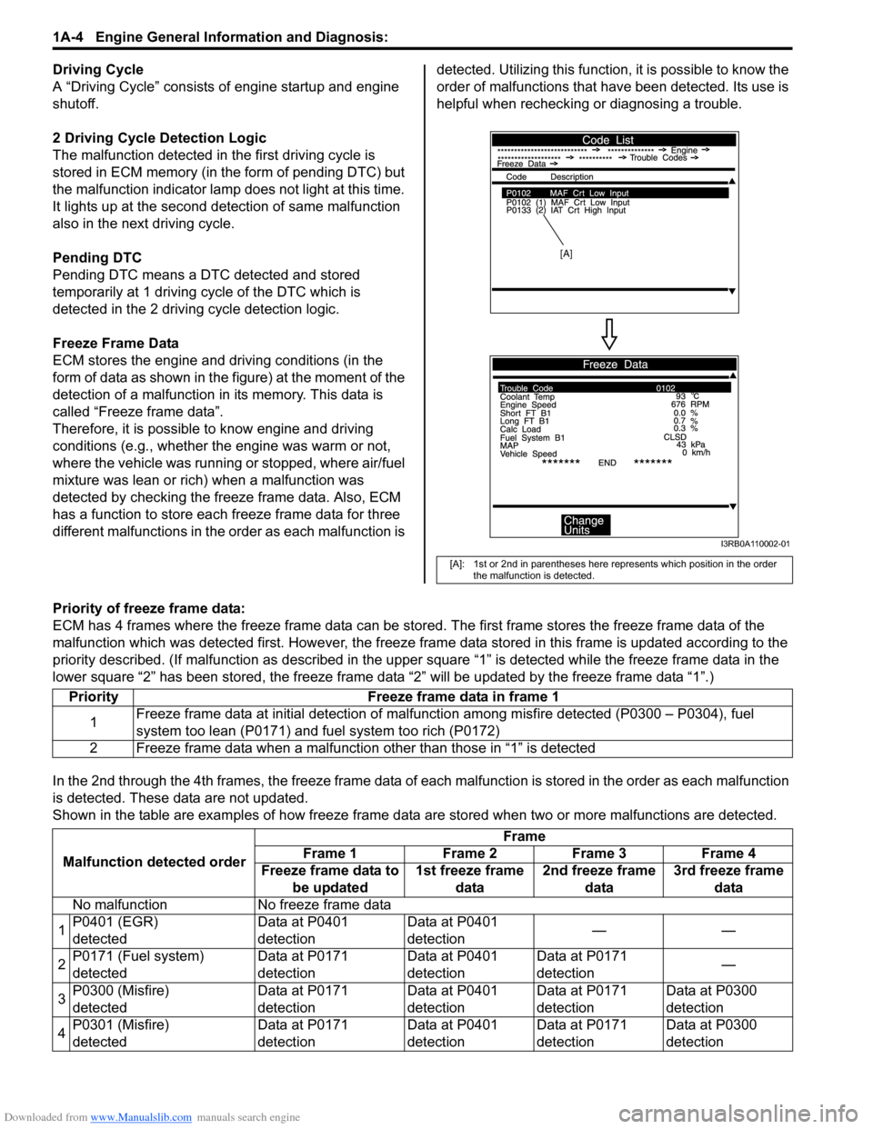
form of data as shown in the figure) at the moment of the
detection of a malfunction in its memory. This data is
called “Freeze frame data”.
Therefore, it is possible to know engine and driving
conditions (e.g., whether the engine was warm or not,
where the vehicle was running or stopped, where air/fuel
mixture was lean or rich) when a malfunction was
detected by checking the freeze frame data. Also, ECM
has a function to store each freeze frame data for three
different malfunctions in the order as each malfunction is detected. Utilizing this function,
it is possible to know the
order of malfunctions that ha ve been detected. Its use is
helpful when rechecking or diagnosing a trouble.
Priority of freeze frame data:
ECM has 4 frames where the freeze frame data can be stor ed. The first frame stores the freeze frame data of the
malfunction which was detected first. Howe ver, the freeze frame data stored in this frame is updated according to the
priority described. (If malfunction as described in the upper square “1” is detected while the freeze frame data in the
lower square “2” has been stored, the freeze frame data “2” will be updated by the freeze frame data “1”.)
In the 2nd through the 4th frames, the freeze frame data of each malfunction is stored in the order as each malfunction
is detected. These data are not updated.
Shown in the table are examples of how freeze frame data are stored when two or more malfunctions are detected.
[A]: 1st or 2nd in parentheses here represents which position in the order
the malfunction is detected.
[A]
I3RB0A110002-01
Priority Freeze frame data in frame 1
1 Freeze frame data at initial detection of malfuncti
on among misfire detected (P0300 – P0304), fuel
system too lean (P0171) and fuel system too rich (P0172)
2 Freeze frame data when a malfunctio n other than those in “1” is detected
Malfunction detected order Frame
Frame 1 Frame 2 Frame 3 Frame 4
Freeze frame data to be updated 1st freeze frame
data 2nd freeze frame
data 3rd freeze frame
data
No malfunction No freeze frame data
1 P0401 (EGR)
detected Data at P0401
detectionData at P0401
detection
——
2 P0171 (Fuel system)
detected Data at P0171
detectionData at P0401
detectionData at P0171
detection
—
3 P0300 (Misfire)
detected Data at P0171
detectionData at P0401
detectionData at P0171
detectionData at P0300
detection
4 P0301 (Misfire)
detected Data at P0171
detectionData at P0401
detectionData at P0171
detectionData at P0300
detection
Page 79 of 1496
Downloaded from www.Manualslib.com manuals search engine Engine General Information and Diagnosis: 1A-29
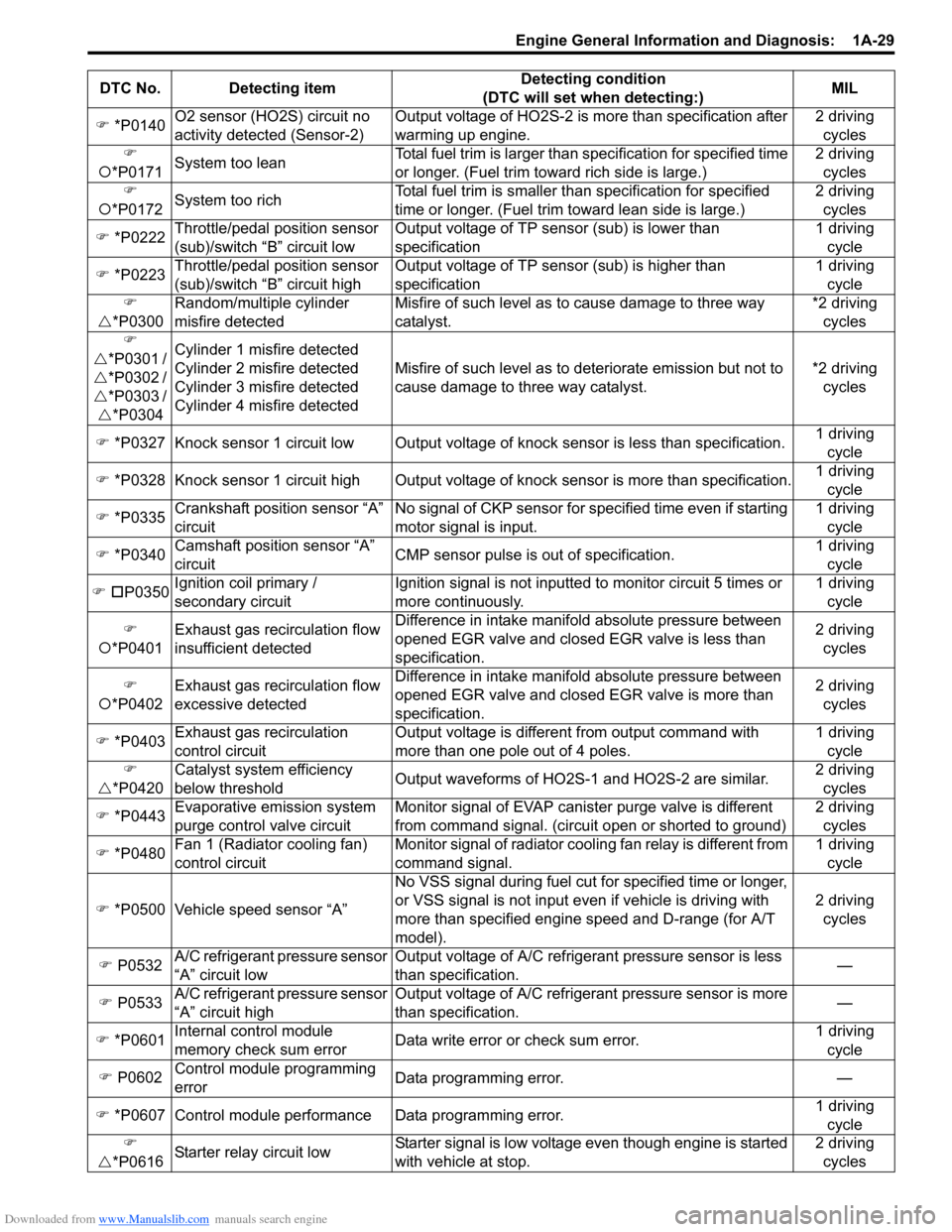
�) *P0140 O2 sensor (HO2S) circuit no
activity detected (Sensor-2) Output voltage of HO2S-2 is more than specification after
warming up engine. 2 driving
cycles
�)
�{ *P0171 System too lean Total fuel trim is larger than
specification for specified time
or longer. (Fuel trim towa rd rich side is large.) 2 driving
cycles
�)
�{ *P0172 System too rich Total fuel trim is smaller th
an specification for specified
time or longer. (Fue l trim toward lean side is large.) 2 driving
cycles
�) *P0222 Throttle/pedal position sensor
(sub)/switch “B” circuit low Output voltage of TP sensor (sub) is lower than
specification 1 driving
cycle
�) *P0223 Throttle/pedal position sensor
(sub)/switch “B” circuit high Output voltage of TP sensor (sub) is higher than
specification 1 driving
cycle
�)
�U *P0300 Random/multiple cylinder
misfire detected Misfire of such level as to cause damage to three way
catalyst. *2 driving
cycles
�)
�U *P0301 /
�U *P0302 /
�U *P0303 /
�U *P0304 Cylinder 1 misfire detected
Cylinder 2 misfire detected
Cylinder 3 misfire detected
Cylinder 4 misfire detected
Misfire of such level as to deteriorate emission but not to
cause damage to three way catalyst.
*2 driving
cycles
�) *P0327 Knock sensor 1 circuit low Output voltage of knock sensor is less than specification.1 driving
cycle
�) *P0328 Knock sensor 1 circuit high Output volta ge of knock sensor is more than specification.1 driving
cycle
�) *P0335 Crankshaft position sensor “A”
circuit No signal of CKP sensor for sp
ecified time even if starting
motor signal is input. 1 driving
cycle
�) *P0340 Camshaft position sensor “A”
circuit CMP sensor pulse is out of specification. 1 driving
cycle
�) �† P0350 Ignition c
oil primary /
secondary circuit Ignition signal is not inputted to monitor circuit 5 times or
more continuously. 1 driving
cycle
�)
�{ *P0401 Exhaust gas recirculation flow
insufficient detected Difference in intake manifold absolute pressure between
opened EGR valve and closed EGR valve is less than
specification. 2 driving
cycles
�)
�{ *P0402 Exhaust gas recirculation flow
excessive detected Difference in intake manifold absolute pressure between
opened EGR valve and closed EGR valve is more than
specification. 2 driving
cycles
�) *P0403 Exhaust gas recirculation
control circuit Output voltage is different from output command with
more than one pole out of 4 poles. 1 driving
cycle
�)
�U *P0420 Catalyst system efficiency
below threshold
Output waveforms of HO2S-1 and HO2S-2 are similar. 2 driving
cycles
�) *P0443 Evaporative emission system
purge control valve circuit Monitor signal of EVAP canister purge valve is different
from command signal. (circuit open or shorted to ground) 2 driving
cycles
�) *P0480 Fan 1 (Radiator cooling fan)
control circuit Monitor signal of radiator cooling fan relay is different from
command signal. 1 driving
cycle
�) *P0500 Vehicle speed sensor “A” No VSS signal during fuel cut fo
r specified time or longer,
or VSS signal is not input even if vehicle is driving with
more than specified engine speed and D-range (for A/T
model). 2 driving
cycles
�) P0532 A/C refrigerant pressure sensor
“A” circuit low Output voltage of A/C refrigerant pressure sensor is less
than specification.
—
�) P0533 A/C refrigerant pressure sensor
“A” circuit high Output voltage of A/C refrigerant pressure sensor is more
than specification.
—
�) *P0601 Internal control module
memory check sum error Data write error or check sum error. 1 driving
cycle
�) P0602 Control module programming
error Data programming error.
—
�) *P0607 Control module performance Data programming error. 1 driving
cycle
�)
�U *P061
6Starter relay circuit low Starter signal is low voltage even though engine is started
with vehicle at stop. 2 driving
cycles
DTC No. Detecting item
Detecting condition
(DTC will set when detecting:) MIL
Page 84 of 1496
Downloaded from www.Manualslib.com manuals search engine 1A-34 Engine General Information and Diagnosis:
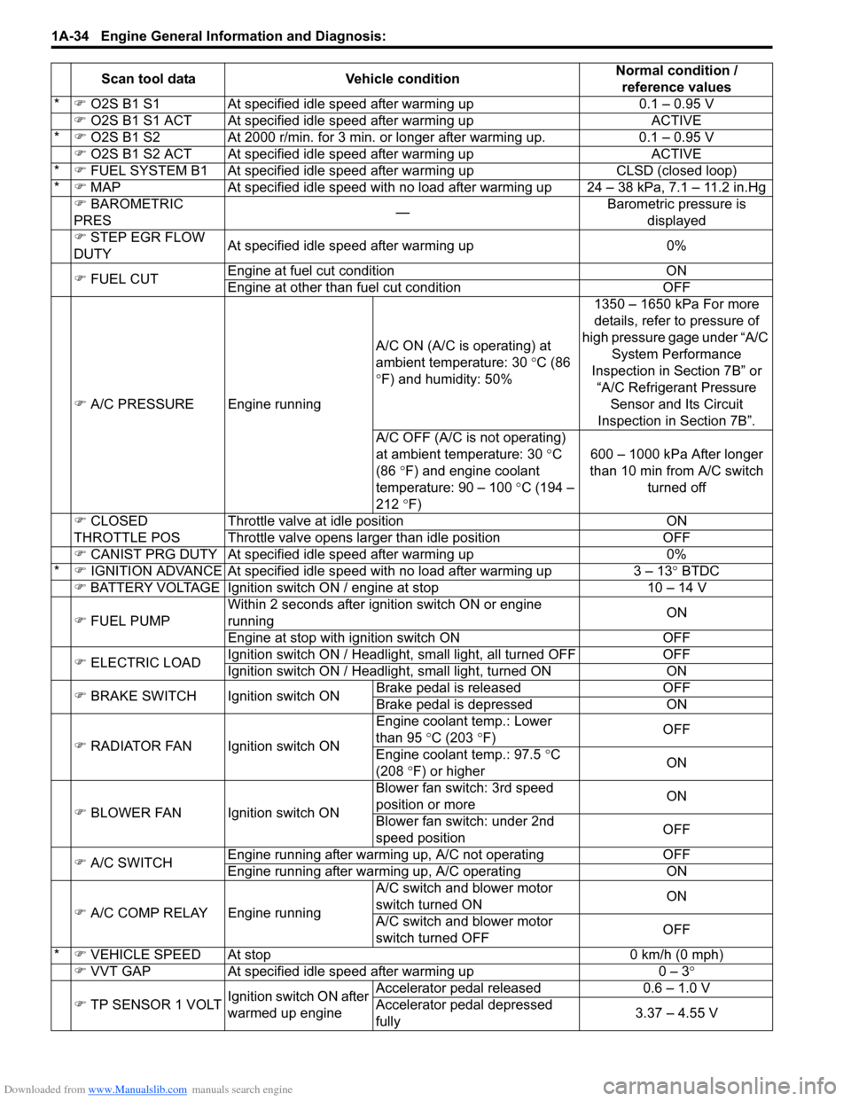
*�) O2S B1 S1 At specified idle speed after warming up 0.1 – 0.95 V
�) O2S B1 S1 ACT At specified id le speed after warming up ACTIVE
* �) O2S B1 S2 At 2000 r/min. for 3 min. or longer after warming up. 0.1 – 0.95 V
�) O2S B1 S2 ACT At specified id le speed after warming up ACTIVE
* �) FUEL SYSTEM B1 At specif ied idle speed after warming up CLSD (closed loop)
* �) MAP At specified idle speed with no load after warming up 24 – 38 kPa, 7.1 – 11.2 in.Hg
�) BAROMETRIC
PRES —Barometric pressure is
displayed
�) STEP EGR FLOW
DUTY At specified idle speed after warming up 0%
�) FUEL CUT Engine at fuel cut condition ON
Engine at other than fuel cut condition OFF
�) A/C PRESSURE Engine running A/C ON (A/C is operating) at
ambient temperature: 30
°C (86
° F) and humidity: 50% 1350 – 1650 kPa For more
details, refer to pressure of
high pressure gage under “A/C System Performance
Inspection in Section 7B” or “A/C Refrigerant Pressure Sensor and Its Circuit
Inspection in Section 7B”.
A/C OFF (A/C is not operating)
at ambient temperature: 30 ° C
(86 °F) and engine coolant
temperature: 90 – 100 °C (194 –
212 °F) 600 – 1000 kPa After longer
than 10 min from A/C switch turned off
�) CLOSED
THROTTLE POS Throttle valve at idle position ON
Throttle valve opens larger than idle position OFF
�) CANIST PRG DUTY At specified idle speed after warming up 0%
* �) IGNITION ADVANCE At specified idle s peed with no load after warming up 3 – 13 ° BTDC
�) BATTERY VOLTAGE Ignition switch ON / engine at stop 10 – 14 V
�) FUEL PUMP Within 2 seconds after ignition switch ON or engine
running
ON
Engine at stop with ignition switch ON OFF
�) ELECTRIC LOAD Ignition switch ON / Headligh
t, small light, all turned OFF OFF
Ignition switch ON / Headli ght, small light, turned ON ON
�) BRAKE SWITCH Igni tion switch ONBrake pedal is released OFF
Brake pedal is depressed ON
�) RADIATOR FAN Ignition switch ON Engin
e coolant temp.: Lower
than 95 °C (203 °F) OFF
Engine coolant temp.: 97.5 °C
(208 °F) or higher ON
�) BLOWER FAN Ignition switch ON Blower fan switch: 3rd speed
position or more
ON
Blower fan switch: under 2nd
speed position OFF
�) A/C SWITCH Engine running after warming up, A/C not operating
OFF
Engine running after warming up, A/C operating ON
�) A/C COMP RELAY Engine running A/C switch and blower motor
switch turned ON
ON
A/C switch and blower motor
switch turned OFF OFF
* �) VEHICLE SPEED At stop 0 km/h (0 mph)
�) VVT GAP At specified idle speed after warming up 0 – 3°
�) TP SENSOR 1 VOLT Ignition switch ON after
warmed up engine Accelerator pedal released
0.6 – 1.0 V
Accelerator pedal depressed
fully 3.37 – 4.55 V
Scan tool data
Vehicle condition Normal condition /
reference values
Page 86 of 1496
Downloaded from www.Manualslib.com manuals search engine 1A-36 Engine General Information and Diagnosis:
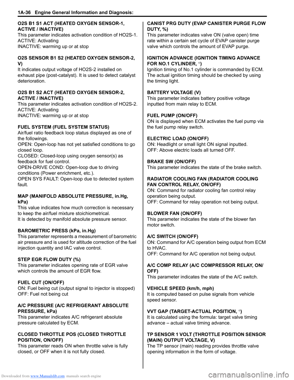
O2S B1 S1 ACT (HEATED OXYGEN SENSOR-1,
ACTIVE / INACTIVE)
This parameter indicates activation condition of HO2S-1.
ACTIVE: Activating
INACTIVE: warming up or at stop
O2S SENSOR B1 S2 (HEATED OXYGEN SENSOR-2,
V)
It indicates output voltage of HO2S-2 installed on
exhaust pipe (post-catalyst). It is used to detect catalyst
deterioration.
O2S B1 S2 ACT (HEATED OXYGEN SENSOR-2,
ACTIVE / INACTIVE)
This parameter indicates acti vation condition of HO2S-2.
ACTIVE: Activating
INACTIVE: warming up or at stop
FUEL SYSTEM (FUEL SYSTEM STATUS)
Air/fuel ratio feedback loop status displayed as one of
the followings.
OPEN: Open-loop has not yet satisfied conditions to go
closed loop.
CLOSED: Closed-loop using oxygen sensor(s) as
feedback for fuel control.
OPEN-DRIVE COND: Open-loop due to driving
conditions (Power enrichment, etc.).
OPEN SYS FAULT: Open-loop due to detected system
fault.
MAP (MANIFOLD ABSOLUTE PRESSURE, in.Hg,
kPa)
This value indicates how much correction is necessary
to keep the air/fuel mixture stoichiometrical.
It is detected by manifold absolute pressure sensor.
BAROMETRIC PRESS (kPa, in.Hg)
This parameter represents a measurement of barometric
air pressure and is used for al titude correction of the fuel
injection quantity and IAC valve control.
STEP EGR FLOW DUTY (%)
This parameter indicates opening rate of EGR valve
which controls the amount of EGR flow.
FUEL CUT (ON/OFF)
ON: Fuel being cut (output signal to injector is stopped)
OFF: Fuel not being cut
A/C PRESSURE (A/C REFRIGERANT ABSOLUTE
PRESSURE, kPa)
This parameter indicates A/C refrigerant absolute
pressure calculated by ECM.
CLOSED THROTTLE PO S (CLOSED THROTTLE
POSITION, ON/OFF)
This parameter reads ON wh en throttle valve is fully
closed, or OFF when it is not fully closed. CANIST PRG DUTY (EVAP CANISTER PURGE FLOW
DUTY, %)
This parameter indicates valve ON (valve open) time
rate within a certain set cycle of EVAP canister purge
valve which controls the amount of EVAP purge.
IGNITION ADVANCE (IGNITION TIMING ADVANCE
FOR NO.1 CYLINDER,
°)
Ignition timing of No.1 cylinder is commanded by ECM.
The actual ignition timing should be checked by using
the timing light.
BATTERY VOLTAGE (V)
This parameter indicates battery positive voltage
inputted from main relay to ECM.
FUEL PUMP (ON/OFF)
ON is displayed when ECM activates the fuel pump via
the fuel pump relay switch.
ELECTRIC LOAD (ON/OFF)
ON: Headlight or small light ON signal inputted.
OFF: Above electric loads all turned OFF.
BRAKE SW (ON/OFF)
This parameter indicates the state of the brake switch.
RADIATOR COOLING FAN (RADIATOR COOLING
FAN CONTROL RELAY, ON/OFF)
ON: Command for radiator cooling fan control relay
operation being output.
OFF: Command for relay operation not being output.
BLOWER FAN (ON/OFF)
This parameter indicates the state of the blower fan
motor switch.
A/C SWITCH (ON/OFF)
ON: Command for A/C operatio n being output from ECM
to HVAC.
OFF: Command for A/C oper ation not being output.
A/C COMP RELAY (A/C COMPRESSOR RELAY, ON/
OFF)
This parameter indicates the state of the A/C switch.
VEHICLE SPEED (km/h, mph)
It is computed based on pulse signals from vehicle
speed sensor.
VVT GAP (TARGET-ACTUAL POSITION, °)
It is calculated using the formula: target valve timing
advance – actual valve timing advance.
TP SENSOR 1 VOLT (THROTTLE POSITION SENSOR
(MAIN) OUTPUT VOLTAGE, V)
The TP sensor (main) reading provides throttle valve
opening information in the form of voltage.
Page 104 of 1496
Downloaded from www.Manualslib.com manuals search engine 1A-54 Engine General Information and Diagnosis:
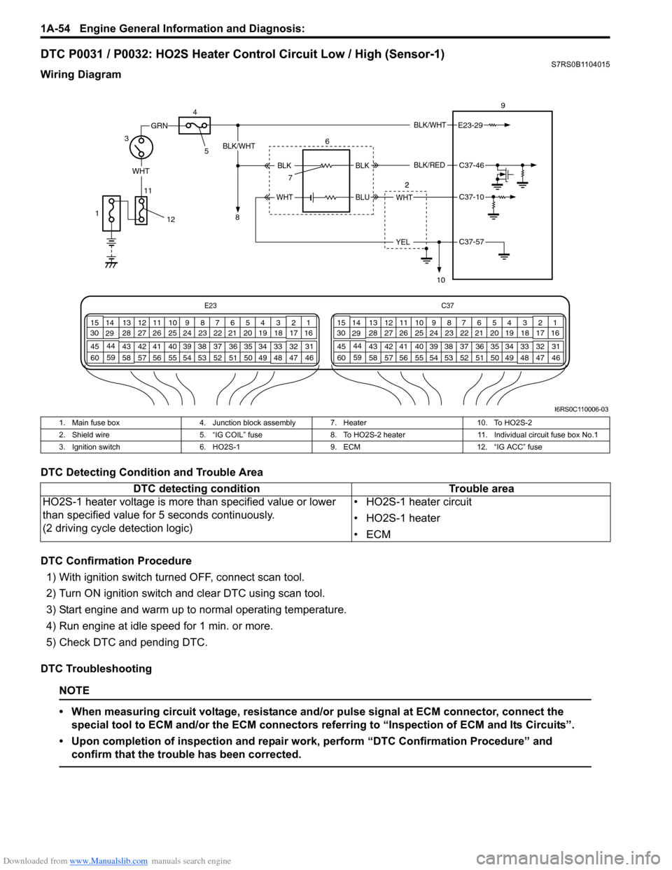
DTC P0031 / P0032: HO2S Heater Control Circuit Low / High (Sensor-1)S7RS0B1104015
Wiring Diagram
DTC Detecting Condition and Trouble Area
DTC Confirmation Procedure1) With ignition switch turned OFF, connect scan tool.
2) Turn ON ignition switch and clear DTC using scan tool.
3) Start engine and warm up to normal operating temperature.
4) Run engine at idle speed for 1 min. or more.
5) Check DTC and pending DTC.
DTC Troubleshooting
NOTE
• When measuring circuit voltage, resistance and/ or pulse signal at ECM connector, connect the
special tool to ECM and/or the ECM connectors re ferring to “Inspection of ECM and Its Circuits”.
• Upon completion of inspection and repair work, perform “DTC Confirmation Procedure” and confirm that the trouble has been corrected.
E23 C37
34
1819
567
1011
17
20
47 46
495051
2122
52 16
25 9
24
14
29
55
57 54 53
59
60 58 2
262728
15
30
56 4832 31
34353637
40
42 39 38
44
45 43 41 331
1213
238
34
1819
567
1011
17
20
47 46
495051
2122
52 16
25 9
24
14
29
55
57 54 53
59
60 58 2
262728
15
30
56 4832 31
34353637
40
42 39 38
44
45 43 41 331
1213
238
BLK/WHT
WHT
11
GRN
3 9
E23-29
WHT
YEL
BLK/WHT
BLKC37-46
C37-10
C37-57
6
7
10
BLK
BLUWHT
BLK/RED
4
5
8
12
1
I6RS0C110006-03
1. Main fuse box
4. Junction block assembly 7. Heater 10. To HO2S-2
2. Shield wire 5. “IG COIL” fuse8. To HO2S-2 heater 11. Individual circuit fuse box No.1
3. Ignition switch 6. HO2S-19. ECM 12. “IG ACC” fuse
DTC detecting condition Trouble area
HO2S-1 heater voltage is more than specified value or lower
than specified value for 5 seconds continuously.
(2 driving cycle detection logic) • HO2S-1 heater circuit
• HO2S-1 heater
•ECM
Page 120 of 1496
Downloaded from www.Manualslib.com manuals search engine 1A-70 Engine General Information and Diagnosis:
DTC Detecting Condition and Trouble Area
DTC Confirmation Procedure
NOTE
Check to make sure that following conditions are satisfied when using this “DTC Confirmation
Procedure”.
• Intake air temperature at engine start: –10 °C (14 ° F) to 80 °C (176 °F)
• Intake air temperature: –10 °C (14 °F) to 70 °C (158 °F)
• Engine coolant temperature at engine start: less than 30 °C (86 °F)
• Engine coolant temperature: 70 °C (158 °F) to 150 °C (302 °F)
• Altitude (barometric pressure): 2400 m, 8000 ft or less (560 mmHg, 75 kPa or more)
1) With ignition switch turned OFF, connect scan tool.
2) Turn ON ignition switch, clear DTC using scan tool.
3) Start engine and warm up to normal operating temperature. (ECT approx. 90 – 95 °C, 194 – 203 °F)
4) Run engine at idle speed for 10 min. or more.
5) Check DTC and pending DTC.
DTC Troubleshooting
NOTE
• When measuring circuit voltage, resistance and/ or pulse signal at ECM connector, connect the
special tool to ECM and/or the ECM connectors re ferring to “Inspection of ECM and Its Circuits”.
• Upon completion of inspection and repair work, perform “DTC Confirmation Procedure” and confirm that the trouble has been corrected.
DTC detecting condition Trouble area
Difference of maximum IAT minus minimum IAT is less than 0.3 °C
(32.5 °F) while ECT is over 70 °C (158 °F) after 10 min from cold
engine start (ECT is lower than 30 °C (86 °F) at engine start).
(2 driving cycle detection logic) • High resistance circuit
• MAF and IAT sensor
•ECM
Step
Action YesNo
1 Was “Engine and Emission Control System Check”
performed? Go to Step 2.
Go to “Engine and
Emission Control
System Check”.
2 IAT sensor and its circuit check
1) Connect scan tool to DLC with ignition switch turned
OFF.
2) Turn ignition switch to ON position.
3) Check intake air temp. displayed on scan tool.
Is –40
°C (–40 °F) or 119 °C (246 °F) indicated? Go to Step 3. Intermittent trouble.
Check for intermittent
referring to “Intermittent
and Poor Connection
Inspection in Section
00”.
Page 142 of 1496
Downloaded from www.Manualslib.com manuals search engine 1A-92 Engine General Information and Diagnosis:
DTC P0134: O2 Sensor (HO2S) Circuit No Activity Detected (Sensor-1)S7RS0B1104033
Wiring Diagram
Refer to “DTC P0131 / P0132: O2 Sensor (HO2S) Circuit Low Voltage / High Voltage (Sensor-1)”
DTC Detecting Condition and Trouble Area
DTC Confirmation Procedure
WARNING!
• When performing a road test, select a place where there is no traffic or possibility of a traffic accident and be very careful during testing to avoid occurrence of an accident.
• Road test should be carried out by 2 persons, a driver and a tester, on a level road.
NOTE
Check to make sure that following conditions ar e satisfied when using this “DTC Confirmation
Procedure”.
• Intake air temperature at engine start: –10 °C (14 ° F) to 80 °C (176 °F)
• Intake air temperature: –10 °C (14 °F) to 70 °C (158 °F)
• Engine Coolant temperature: 70 °C (158 °F) to 150 °C (302 ° F)
• Altitude (barometric pressure): 2400 m, 8000 ft or less (560 mmHg, 75 kPa or more)
1) With ignition switch turned OFF, connect scan tool.
2) Turn ON ignition switch and clear DTC using scan tool.
3) Start engine and warm up to normal operating temperature.
4) Drive vehicle at 40 mph (60 km/h) or higher. (engine speed: 2500 – 3000 r/min.)
5) Keep above vehicle speed for 6 min. or more. (Throt tle valve opening is kept constant in this step.)
6) Release accelerator pedal and with engine brake applied, keep vehicle coasting (with fuel cut for 3 sec. or more)
and then stop vehicle.
7) Check if DTC and pending DTC exist by using scan tool. If not, check if oxygen sensor monitoring test has been
completed by using scan tool. If not in both of above c hecks (i.e., no DTC and pending DTC and oxygen sensor
monitoring test not completed), check vehicle cond ition (environmental) and repeat Step 3) through 6).
DTC Troubleshooting
NOTE
• When measuring circuit voltage, resistance and/ or pulse signal at ECM connector, connect the
special tool to ECM and/or the ECM connectors re ferring to “Inspection of ECM and Its Circuits”.
• Upon completion of inspection and repair work, perform “DTC Confirmation Procedure” and confirm that the trouble has been corrected.
DTC detecting condition Trouble area
HO2S voltage is higher than 0.6 V for more than 1 min
continuously after warming up engine or HO2S voltage is lower
than 0.3 V for more than 1 min continuously after warming up
engine.
(2 driving cycle detection logic) •HO2S-1
• HO2S-1 circuit
• Exhaust gas leakage
•ECM
• Air intake system
Step
Action YesNo
1 Was “Engine and Emission Control System Check”
performed? Go to Step 2.
Go to “Engine and
Emission Control
System Check”.
Page 170 of 1496
Downloaded from www.Manualslib.com manuals search engine 1A-120 Engine General Information and Diagnosis:
DTC P0420: Catalyst System Efficiency below ThresholdS7RS0B1104046
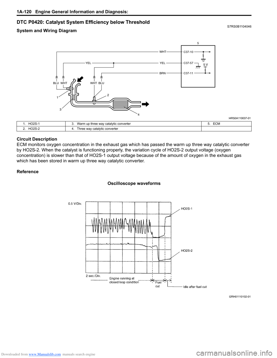
System and Wiring Diagram
Circuit Description
ECM monitors oxygen concentration in the exhaust gas which has passed the warm up three way catalytic converter
by HO2S-2. When the catalyst is functioning properly, the variation cycle of HO2S-2 output voltage (oxygen
concentration) is slower than that of HO2S-1 output voltage because of the amount of oxygen in the exhaust gas
which has been stored in warm up three way catalytic converter.
Reference
Oscilloscope waveforms
C37-11
C37-10
C37-57
WHT
BRN
1
3 2
4
5 VYELYEL
BLUWHTBLUWHT 5
I4RS0A110037-01
1. HO2S-1
3. Warm up three way catalytic converter 5. ECM
2. HO2S-2 4. Three way catalytic converter
I2RH01110102-01
Page 188 of 1496
Downloaded from www.Manualslib.com manuals search engine 1A-138 Engine General Information and Diagnosis:
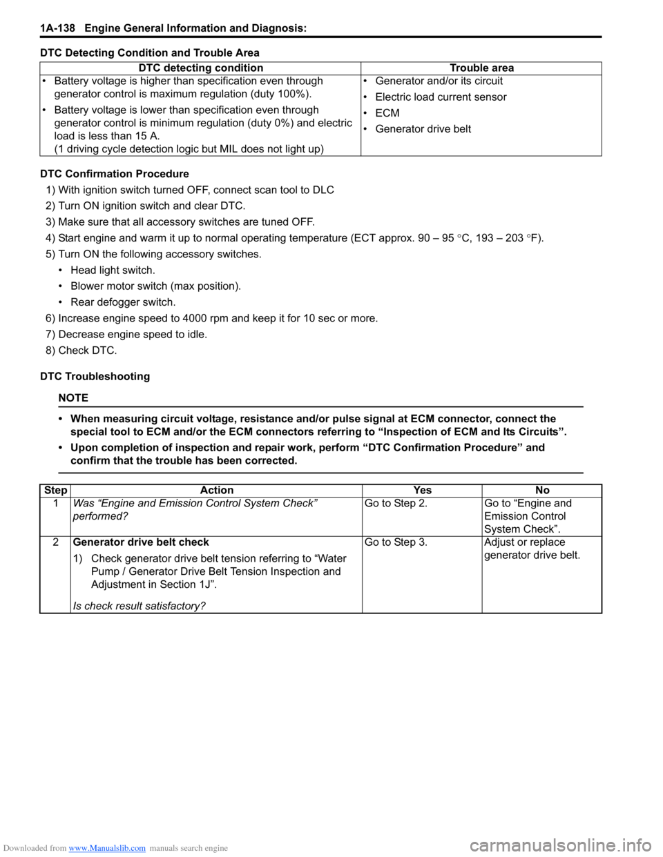
DTC Detecting Condition and Trouble Area
DTC Confirmation Procedure1) With ignition switch turned OFF, connect scan tool to DLC
2) Turn ON ignition switch and clear DTC.
3) Make sure that all accessory switches are tuned OFF.
4) Start engine and warm it up to normal operating temperature (ECT approx. 90 – 95 °C, 193 – 203 °F).
5) Turn ON the followi ng accessory switches.
• Head light switch.
• Blower motor switch (max position).
• Rear defogger switch.
6) Increase engine speed to 4000 rpm and keep it for 10 sec or more.
7) Decrease engine speed to idle.
8) Check DTC.
DTC Troubleshooting
NOTE
• When measuring circuit voltage, resistance and/ or pulse signal at ECM connector, connect the
special tool to ECM and/or the ECM connectors re ferring to “Inspection of ECM and Its Circuits”.
• Upon completion of inspection and repair work, perform “DTC Confirmation Procedure” and confirm that the trouble has been corrected.
DTC detecting condition Trouble area
• Battery voltage is higher than specification even through generator control is maximum regulation (duty 100%).
• Battery voltage is lower than specification even through generator control is minimum regulation (duty 0%) and electric
load is less than 15 A.
(1 driving cycle detection logic but MIL does not light up) • Generator and/or its circuit
• Electric load current sensor
•ECM
• Generator drive belt
Step
Action YesNo
1 Was “Engine and Emission Control System Check”
performed? Go to Step 2.
Go to “Engine and
Emission Control
System Check”.
2 Generator drive belt check
1) Check generator drive belt tension referring to “Water
Pump / Generator Drive Belt Tension Inspection and
Adjustment in Section 1J”.
Is check result satisfactory? Go to Step 3.
Adjust or replace
generator drive belt.
Page 190 of 1496
Downloaded from www.Manualslib.com manuals search engine 1A-140 Engine General Information and Diagnosis:
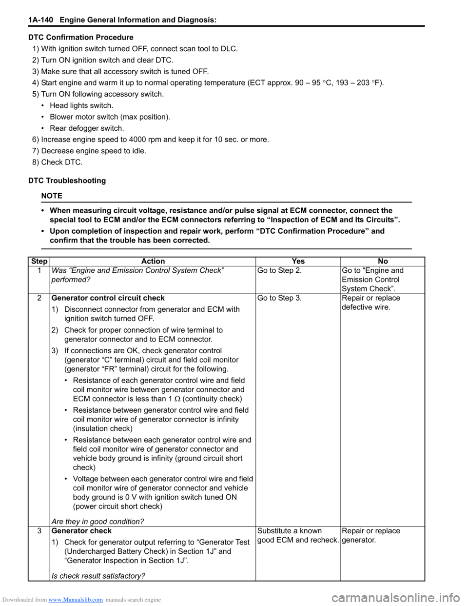
DTC Confirmation Procedure1) With ignition switch turned OFF, connect scan tool to DLC.
2) Turn ON ignition switch and clear DTC.
3) Make sure that all accessory switch is tuned OFF.
4) Start engine and warm it up to normal operating temperature (ECT approx. 90 – 95 °C, 193 – 203 °F).
5) Turn ON following accessory switch. • Head lights switch.
• Blower motor switch (max position).
• Rear defogger switch.
6) Increase engine speed to 4000 rpm and keep it for 10 sec. or more.
7) Decrease engine speed to idle.
8) Check DTC.
DTC Troubleshooting
NOTE
• When measuring circuit voltage, resistance and/ or pulse signal at ECM connector, connect the
special tool to ECM and/or the ECM connectors re ferring to “Inspection of ECM and Its Circuits”.
• Upon completion of inspection and repair work, perform “DTC Confirmation Procedure” and confirm that the trouble has been corrected.
Step Action YesNo
1 Was “Engine and Emission Control System Check”
performed? Go to Step 2.
Go to “Engine and
Emission Control
System Check”.
2 Generator control circuit check
1) Disconnect connector from generator and ECM with
ignition switch turned OFF.
2) Check for proper connection of wire terminal to generator connector and to ECM connector.
3) If connections are OK, check generator control (generator “C” terminal) circuit and field coil monitor
(generator “FR” terminal) circuit for the following.
• Resistance of each generato r control wire and field
coil monitor wire between generator connector and
ECM connector is less than 1 Ω (continuity check)
• Resistance between generator control wire and field coil monitor wire of generator connector is infinity
(insulation check)
• Resistance between each generator control wire and field coil monitor wire of generator connector and
vehicle body ground is infinity (ground circuit short
check)
• Voltage between each generator control wire and field
coil monitor wire of generator connector and vehicle
body ground is 0 V with ignition switch tuned ON
(power circuit short check)
Are they in good condition? Go to Step 3.
Repair or replace
defective wire.
3 Generator check
1) Check for generator output referring to “Generator Test
(Undercharged Battery Check) in Section 1J” and
“Generator Inspection in Section 1J”.
Is check result satisfactory? Substitute a known
good ECM and recheck.
Repair or replace
generator.