Ignition coil jb SUZUKI SWIFT 2007 2.G Service Owners Manual
[x] Cancel search | Manufacturer: SUZUKI, Model Year: 2007, Model line: SWIFT, Model: SUZUKI SWIFT 2007 2.GPages: 1496, PDF Size: 34.44 MB
Page 1077 of 1496
Downloaded from www.Manualslib.com manuals search engine Air Bag System: 8B-39
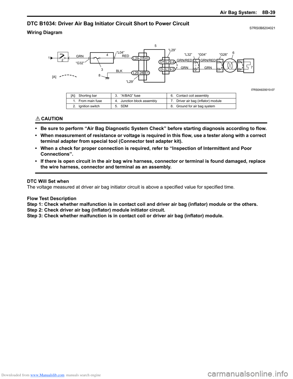
DTC B1034: Driver Air Bag Initiator Circuit Short to Power CircuitS7RS0B8204021
Wiring Diagram
CAUTION!
• Be sure to perform “Air Bag Diagnostic System Check” before starting diagnosis according to flow.
• When measurement of resistance or voltage is required in this flow, use a tester along with a correct terminal adapter from special tool (Connector test adapter kit).
• When a check for proper connection is required, refer to “Inspection of Intermittent and Poor Connections”.
• If there is open circuit in the air bag wire harnes s, connector or terminal is found damaged, replace
the wire harness, connector and terminal as an assembly.
DTC Will Set when
The voltage measured at driver air bag initiator ci rcuit is above a specified value for specified time.
Flow Test Description
Step 1: Check whether malfunction is in contact coil and driver air bag (inflator) module or the others.
Step 2: Check driver air bag (inflator) module initiator circuit.
Step 3: Check whether malfunction is in contact coil or driver air bag (inflator) module.
1 2
3
GRN
RED
8
BLK
L29-27
L29-28 IG
E1
4
“L29”
“L04”
“G32”
“L29”
L29-4
D+
L29-3
D-GRN
GRN/RED
GRN
GRN/RED 6
57
“G26”
“L32” “G04”
[A]
I7RS0A820010-07
[A]: Shorting bar 3. “A/BAG” fuse 6. Contact coil assembly
1. From main fuse 4. Junction block assembly 7. Driver air bag (inflator) module
2. Ignition switch 5. SDM 8. Ground for air bag system
Page 1078 of 1496
Downloaded from www.Manualslib.com manuals search engine 8B-40 Air Bag System:
DTC TroubleshootingStep Action YesNo
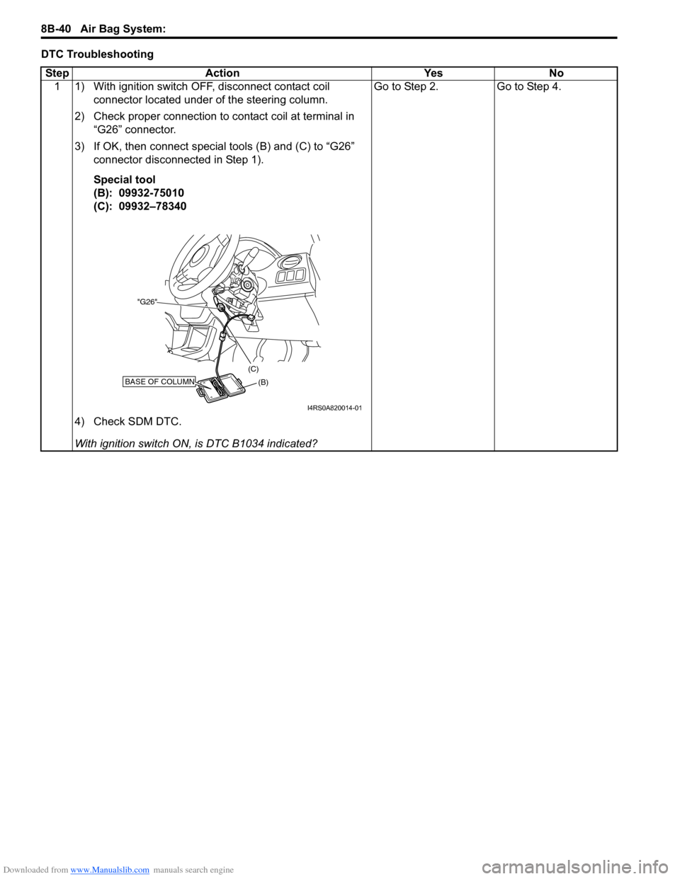
1 1) With ignition switch OFF, disconnect contact coil connector located under of the steering column.
2) Check proper connection to contact coil at terminal in “G26” connector.
3) If OK, then connect special tools (B) and (C) to “G26” connector disconnected in Step 1).
Special tool
(B): 09932-75010
(C): 09932–78340
4) Check SDM DTC.
With ignition switch ON , is DTC B1034 indicated? Go to Step 2.
Go to Step 4.
BASE OF COLUMN(B)
(C)
"G26"
I4RS0A820014-01
Page 1081 of 1496
Downloaded from www.Manualslib.com manuals search engine Air Bag System: 8B-43
NOTE
Upon completion of inspection and repair work, perform the following items.
• Reconnect all air bag system components and ensure all components are properly mounted.
• Clear DTCs referring to “DTC Clearance”, if any.
• Repeat “Air Bag Diagnostic System Check” to confirm that the trouble has been corrected.
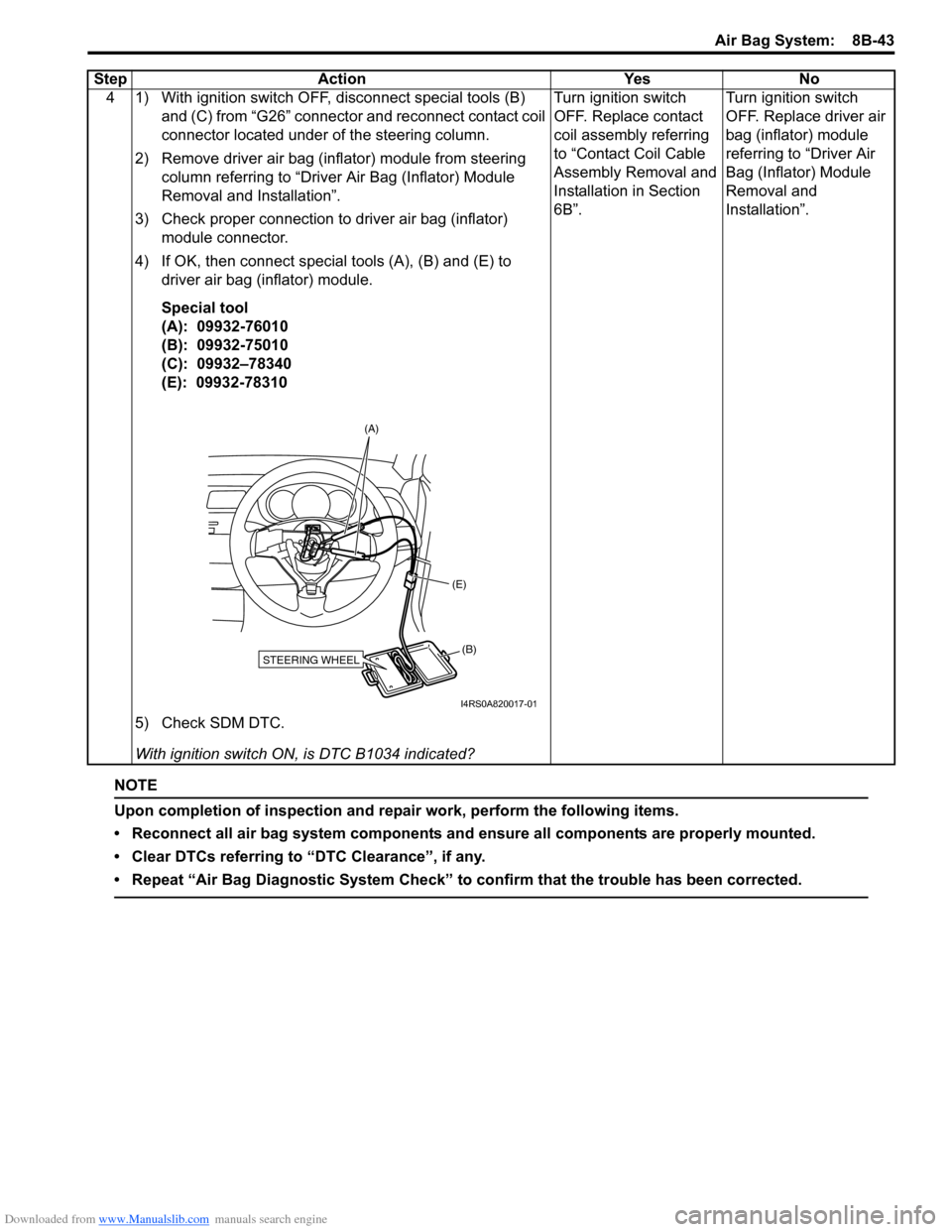
4 1) With ignition switch OFF, disconnect special tools (B) and (C) from “G26” connector and reconnect contact coil
connector located under of the steering column.
2) Remove driver air bag (inflator) module from steering column referring to “Driver Air Bag (Inflator) Module
Removal and Installation”.
3) Check proper connection to driver air bag (inflator) module connector.
4) If OK, then connect special tools (A), (B) and (E) to driver air bag (inflator) module.
Special tool
(A): 09932-76010
(B): 09932-75010
(C): 09932–78340
(E): 09932-78310
5) Check SDM DTC.
With ignition switch ON , is DTC B1034 indicated? Turn ignition switch
OFF. Replace contact
coil assembly referring
to “Contact Coil Cable
Assembly Removal and
Installation in Section
6B”.
Turn ignition switch
OFF. Replace driver air
bag (inflator) module
referring to “Driver Air
Bag (Inflator) Module
Removal and
Installation”.
Step Action Yes No
STEERING WHEEL(B)
(E)
(A)
I4RS0A820017-01
Page 1131 of 1496
Downloaded from www.Manualslib.com manuals search engine Air Bag System: 8B-93
Contact Coil Cable and Its Circuit CheckS7RS0B8204047
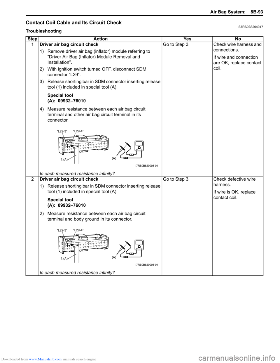
TroubleshootingStep Action Yes No 1 Driver air bag circuit check
1) Remove driver air bag (inflator) module referring to
“Driver Air Bag (Inflator) Module Removal and
Installation”.
2) With ignition switch turned OFF, disconnect SDM connector “L29”.
3) Release shorting bar in SDM connector inserting release tool (1) included in special tool (A).
Special tool
(A): 09932–76010
4) Measure resistance between each air bag circuit terminal and other air bag circuit terminal in its
connector.
Is each measured resistance infinity? Go to Step 3. Check wire harness and
connections.
If wire and connection
are OK, replace contact
coil.
2 Driver air bag circuit check
1) Release shorting bar in SDM connector inserting release
tool (1) included in special tool (A).
Special tool
(A): 09932–76010
2) Measure resistance between each air bag circuit terminal and body ground in its connector.
Is each measured resistance infinity? Go to Step 3. Check defective wire
harness.
If wire is OK, replace
contact coil.
“L29-4”
“L29-3”
1,(A)(A)
I7RS0B820003-01
“L29-4”
“L29-3”
1,(A)(A)
I7RS0B820003-01
Page 1172 of 1496
Downloaded from www.Manualslib.com manuals search engine 9A-1 Wiring Systems:
Body, Cab and Accessories
Wiring Systems
Precautions
Cautions in Body Electrical System ServicingS7RS0B9100001
When servicing the electric systems, observe the cautions described in “Precautions for Electrical Circuit Service in
Section 00” to protect electrical parts and to prevent a fire.
General Description
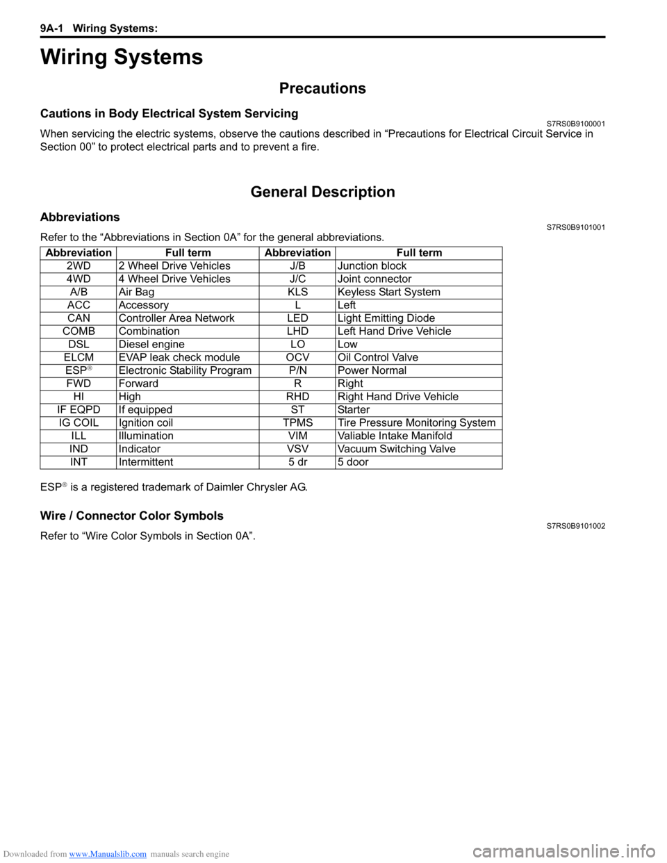
AbbreviationsS7RS0B9101001
Refer to the “Abbreviations in Sect ion 0A” for the general abbreviations.
ESP
® is a registered trademark of Daimler Chrysler AG.
Wire / Connector Color SymbolsS7RS0B9101002
Refer to “Wire Color Sy mbols in Section 0A”.
Abbreviation Full term Abbreviation Full term
2WD 2 Wheel Drive Vehicles J/B Junction block
4WD 4 Wheel Drive Vehicles J/C Joint connectorA/B Air Bag KLS Keyless Start System
ACC Accessory L Left
CAN Controller Area Network LED Light Emitting Diode
COMB Combination LHD Left Hand Drive Vehicle DSL Diesel engine LO Low
ELCM EVAP leak check module OCV Oil Control Valve ESP
®Electronic Stability Program P/N Power Normal
FWD Forward R Right HI High RHD Right Hand Drive Vehicle
IF EQPD If equipped ST Starter IG COIL Ignition coil TPMS Tire Pressure Monitoring System ILL Illumination VIM Valiable Intake Manifold
IND Indicator VSV Vacuum Switching Valve INT Intermittent 5 dr 5 door
Page 1219 of 1496
Downloaded from www.Manualslib.com manuals search engine Wiring Systems: 9A-48
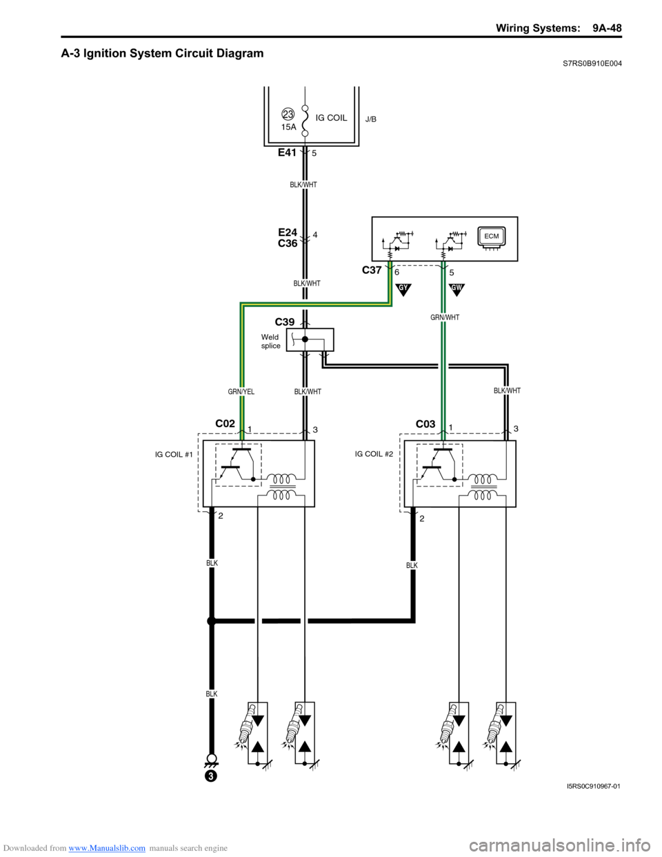
A-3 Ignition System Circuit DiagramS7RS0B910E004
15A
4E24
C36
2
C021 3
IG COIL #1
C03
BLK
BLK/WHTGRN/YEL
BLK/WHT
J/B
ECM
GYGW
23IG COIL
BLK
BLK
IG COIL #2
E415
3
GRN/WHT
1
3
2
C375
6
Weld
splice
C39
BLK/WHT
BLK/WHT
I5RS0C910967-01
Page 1445 of 1496
Downloaded from www.Manualslib.com manuals search engine Immobilizer Control System: 10C-2
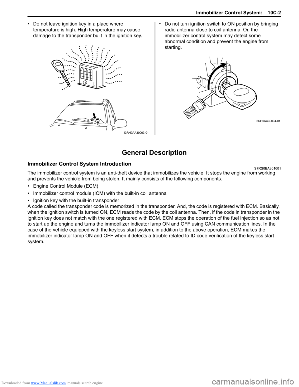
• Do not leave ignition key in a place where
temperature is high. High temperature may cause
damage to the transponder built in the ignition key. • Do not turn ignition switch to ON position by bringing
radio antenna close to coil antenna. Or, the
immobilizer control syst em may detect some
abnormal condition and prevent the engine from
starting.
General Description
Immobilizer Control System IntroductionS7RS0BA301001
The immobilizer control system is an anti-theft device that immobilizes the vehicle. It stops the engine from working
and prevents the vehicle from being stolen. It mainly consists of the following components.
• Engine Control Module (ECM)
• Immobilizer control module (ICM) with the built-in coil antenna
• Ignition key with the built-in transponder
A code called the transponder code is memorized in the tran sponder. And, the code is registered with ECM. Basically,
when the ignition switch is turned ON, ECM reads the code by the coil antenna. Then, if the code in transponder in the
ignition key does not match with the one registered with ECM, ECM stops the operati on of the fuel injection so as not
to start up the engine and turns the immobilizer indi cator lamp ON and OFF using CA N communication lines. In the
case of the vehicle equipped with the keyless start system , in addition to the above operation, ECM makes the
immobilizer indicator lamp ON and OFF when it detects a trouble related to ID code verification of the keyless start
system.
I3RH0AA30003-01
I3RH0AA30004-01
Page 1450 of 1496
Downloaded from www.Manualslib.com manuals search engine 10C-7 Immobilizer Control System:
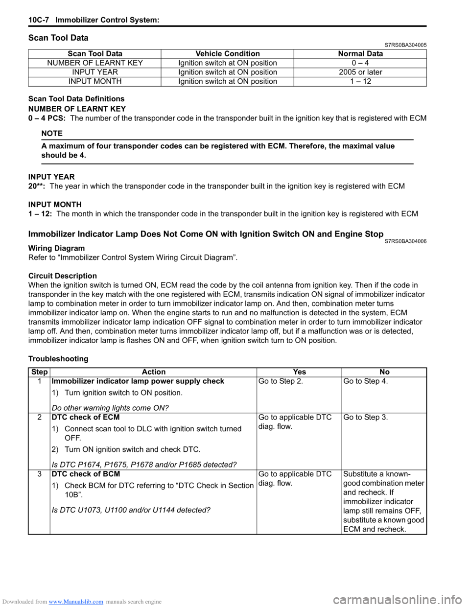
Scan Tool DataS7RS0BA304005
Scan Tool Data Definitions
NUMBER OF LEARNT KEY
0 – 4 PCS: The number of the transponder code in the transponder built in the ignition key that is registered with ECM
NOTE
A maximum of four transponder codes can be registered with ECM. Therefore, the maximal value
should be 4.
INPUT YEAR
20**: The year in which the transponder code in the transpon der built in the ignition key is registered with ECM
INPUT MONTH
1 – 12: The month in which the transponder code in the transpond er built in the ignition key is registered with ECM
Immobilizer Indicator Lamp Does Not Come ON with Ignition Switch ON and Engine StopS7RS0BA304006
Wiring Diagram
Refer to “Immobilizer Control System Wiring Circuit Diagram”.
Circuit Description
When the ignition switch is turned ON, ECM read the code by the coil antenna from ignition key. Then if the code in
transponder in the key match with the one registered with ECM, transmits indication ON signal of immobilizer indicator
lamp to combination meter in order to turn immobilizer indicator lamp on. And then, combination meter turns
immobilizer indicator lamp on. When th e engine starts to run and no malfunction is detected in the system, ECM
transmits immobilizer indi cator lamp indication OFF signal to combination meter in order to turn immobilizer indicator
lamp off. And then, comb ination meter turns immobilizer indicator lamp off, but if a malfunction was or is detected,
immobilizer indicator lamp is flashes ON and OF F, when ignition switch turn to ON position.
Troubleshooting Scan Tool Data Vehicl
e Condition Normal Data
NUMBER OF LEARNT KEY Ignition switch at ON position 0 – 4 INPUT YEAR Ignition switch at ON position 2005 or later
INPUT MONTH Ignition switch at ON position 1 – 12
Step Action YesNo
1 Immobilizer indicator lamp power supply check
1) Turn ignition switch to ON position.
Do other warning lights come ON? Go to Step 2.
Go to Step 4.
2 DTC check of ECM
1) Connect scan tool to DLC with ignition switch turned
OFF.
2) Turn ON ignition switch and check DTC.
Is DTC P1674, P1675, P1678 and/or P1685 detected? Go to applicable DTC
diag. flow.
Go to Step 3.
3 DTC check of BCM
1) Check BCM for DTC referring to “DTC Check in Section
10B”.
Is DTC U1073, U1100 and/or U1144 detected? Go to applicable DTC
diag. flow.
Substitute a known-
good combination meter
and recheck. If
immobilizer indicator
lamp still remains OFF,
substitute a known good
ECM and recheck.
Page 1451 of 1496
Downloaded from www.Manualslib.com manuals search engine Immobilizer Control System: 10C-8
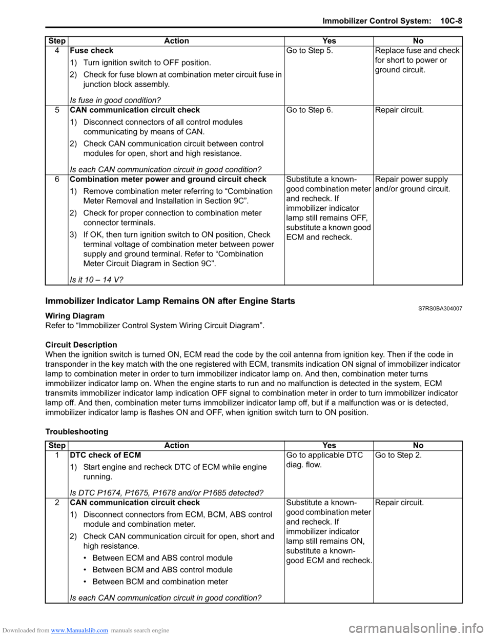
Immobilizer Indicator Lamp Remains ON after Engine StartsS7RS0BA304007
Wiring Diagram
Refer to “Immobilizer Control S ystem Wiring Circuit Diagram”.
Circuit Description
When the ignition switch is turned ON, ECM read the code by the coil antenna from ignition key. Then if the code in
transponder in the key match with the one registered with ECM, transmits indication ON signal of immobilizer indicator
lamp to combination meter in order to turn immobilizer indicator lamp on. And then, combination meter turns
immobilizer indicator lamp on. When th e engine starts to run and no malfunction is detected in the system, ECM
transmits immobilizer indicator lamp indication O FF signal to combination meter in order to turn immobilizer indicator
lamp off. And then, comb ination meter turns immobilizer indicator lamp off, but if a malfunction was or is detected,
immobilizer indicator lamp is flashes ON and OF F, when ignition switch turn to ON position.
Troubleshooting 4
Fuse check
1) Turn ignition switch to OFF position.
2) Check for fuse blown at combination meter circuit fuse in
junction block assembly.
Is fuse in good condition? Go to Step 5. Replace fuse and check
for short to power or
ground circuit.
5 CAN communication circuit check
1) Disconnect connectors of all control modules
communicating by means of CAN.
2) Check CAN communication circuit between control modules for open, short and high resistance.
Is each CAN communication circuit in good condition? Go to Step 6. Repair circuit.
6 Combination meter power and ground circuit check
1) Remove combination meter referring to “Combination
Meter Removal and Installation in Section 9C”.
2) Check for proper connection to combination meter connector terminals.
3) If OK, then turn ignition switch to ON position, Check terminal voltage of combination meter between power
supply and ground terminal. Refer to “Combination
Meter Circuit Diagram in Section 9C”.
Is it 10 – 14 V? Substitute a known-
good combination meter
and recheck. If
immobilizer indicator
lamp still remains OFF,
substitute a known good
ECM and recheck.
Repair power supply
and/or ground circuit.
Step Action Yes No
Step
Action YesNo
1 DTC check of ECM
1) Start engine and recheck DTC of ECM while engine
running.
Is DTC P1674, P1675, P1678 and/or P1685 detected? Go to applicable DTC
diag. flow.
Go to Step 2.
2 CAN communication circuit check
1) Disconnect connectors from ECM, BCM, ABS control
module and combination meter.
2) Check CAN communication circuit for open, short and high resistance.
• Between ECM and ABS control module
• Between BCM and ABS control module
• Between BCM and combination meter
Is each CAN communication circuit in good condition? Substitute a known-
good combination meter
and recheck. If
immobilizer indicator
lamp still remains ON,
substitute a known-
good ECM and recheck.
Repair circuit.