Meter SUZUKI SWIFT 2007 2.G Service Workshop Manual
[x] Cancel search | Manufacturer: SUZUKI, Model Year: 2007, Model line: SWIFT, Model: SUZUKI SWIFT 2007 2.GPages: 1496, PDF Size: 34.44 MB
Page 625 of 1496
Downloaded from www.Manualslib.com manuals search engine Electronic Stability Program: 4F-51
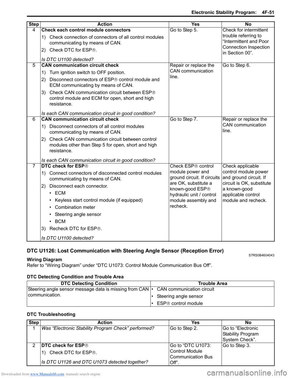
DTC U1126: Lost Communication with Steering Angle Sensor (Reception Error)S7RS0B4604043
Wiring Diagram
Refer to “Wiring Diagram” under “DTC U1073: Control Module Communication Bus Off”.
DTC Detecting Condition and Trouble Area
DTC Troubleshooting4
Check each control module connectors
1) Check connection of connectors of all control modules
communicating by means of CAN.
2) Check DTC for ESP ®.
Is DTC U1100 detected? Go to Step 5. Check for intermittent
trouble referring to
“Intermittent and Poor
Connection Inspection
in Section 00”.
5 CAN communication circuit check
1) Turn ignition switch to OFF position.
2) Disconnect connectors of ESP ® control module and
ECM communicating by means of CAN.
3) Check CAN communication circuit between ESP®
control module and ECM for open, short and high
resistance.
Is each CAN communication circuit in good condition? Repair or replace the
CAN communication
line.
Go to Step 6.
6 CAN communication circuit check
1) Disconnect connectors of all control modules
communicating by means of CAN.
2) Check CAN communication circuit between control modules other than Step 5 for open, short and high
resistance.
Is each CAN communication circuit in good condition? Go to Step 7. Repair or replace the
CAN communication
line.
7 DTC check for ESP®
1) Connect connectors of disconnected control modules
communicating by means of CAN.
2) Disconnect each connector. •ECM
• Keyless start control module (if equipped)
• Combination meter
• Steering angle sensor
•BCM
3) Recheck DTC for ESP ®.
Is DTC U1100 detected? Check ESP
® control
module power and
ground circuit. If circuits
are OK, substitute a
known-good ESP ®
hydraulic unit / control
module assembly and
recheck. Check applicable
control module power
and ground circuit. If
circuit is OK, substitute
a known-good
applicable control
module and recheck.
Step Action Yes No
DTC Detecting Condition
Trouble Area
Steering angle sensor message data is missing from CAN
communication. • CAN communication circuit
• Steering angle sensor
• ESP
® control module
Step Action YesNo
1 Was “Electronic Stability Pr ogram Check” performed? Go to Step 2.Go to “Electronic
Stability Program
System Check”.
2 DTC check for ESP®
1) Check DTC for ESP ®.
Is DTC U1126 and DTC U1073 detected together? Go to “DTC U1073:
Control Module
Communication Bus
Off”.Go to Step 3.
Page 626 of 1496
Downloaded from www.Manualslib.com manuals search engine 4F-52 Electronic Stability Program:
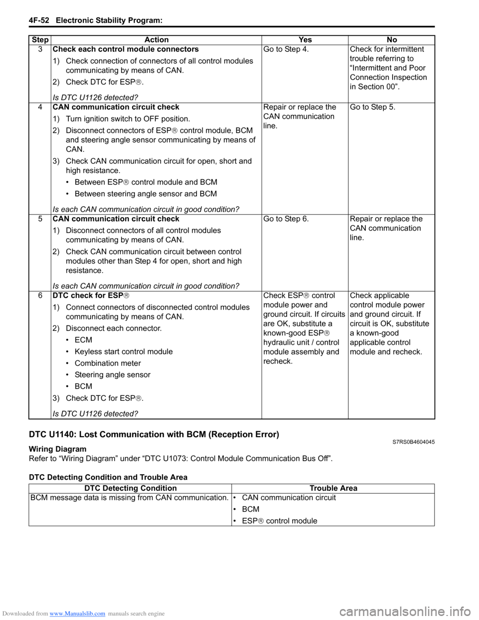
DTC U1140: Lost Communication with BCM (Reception Error)S7RS0B4604045
Wiring Diagram
Refer to “Wiring Diagram” under “DTC U1073: Control Module Communication Bus Off”.
DTC Detecting Condition and Trouble Area3
Check each control module connectors
1) Check connection of connectors of all control modules
communicating by means of CAN.
2) Check DTC for ESP ®.
Is DTC U1126 detected? Go to Step 4. Check for intermittent
trouble referring to
“Intermittent and Poor
Connection Inspection
in Section 00”.
4 CAN communication circuit check
1) Turn ignition switch to OFF position.
2) Disconnect connectors of ESP ® control module, BCM
and steering angle sensor communicating by means of
CAN.
3) Check CAN communication circuit for open, short and high resistance.
• Between ESP ® control module and BCM
• Between steering angle sensor and BCM
Is each CAN communication circuit in good condition? Repair or replace the
CAN communication
line.
Go to Step 5.
5 CAN communication circuit check
1) Disconnect connectors of all control modules
communicating by means of CAN.
2) Check CAN communication circuit between control modules other than Step 4 for open, short and high
resistance.
Is each CAN communication circuit in good condition? Go to Step 6. Repair or replace the
CAN communication
line.
6 DTC check for ESP®
1) Connect connectors of disconnected control modules
communicating by means of CAN.
2) Disconnect each connector. •ECM
• Keyless start control module
• Combination meter
• Steering angle sensor
•BCM
3) Check DTC for ESP ®.
Is DTC U1126 detected? Check ESP
® control
module power and
ground circuit. If circuits
are OK, substitute a
known-good ESP ®
hydraulic unit / control
module assembly and
recheck. Check applicable
control module power
and ground circuit. If
circuit is OK, substitute
a known-good
applicable control
module and recheck.
Step Action Yes No
DTC Detecting Condition
Trouble Area
BCM message data is missing from CAN communication. • CAN communication circuit
•BCM
• ESP® control module
Page 627 of 1496
Downloaded from www.Manualslib.com manuals search engine Electronic Stability Program: 4F-53
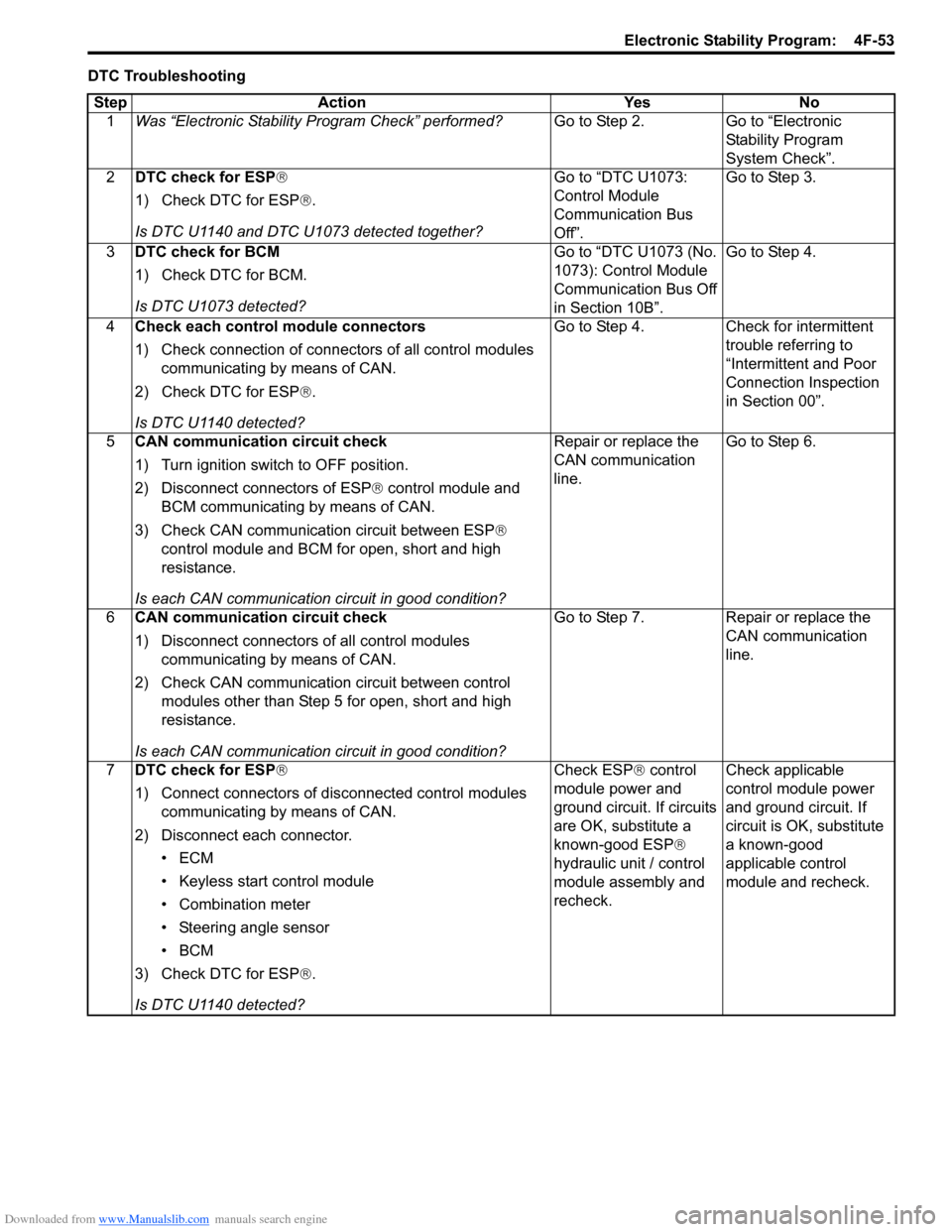
DTC TroubleshootingStep Action Yes No 1 Was “Electronic Stability Pr ogram Check” performed? Go to Step 2. Go to “Electronic
Stability Program
System Check”.
2 DTC check for ESP®
1) Check DTC for ESP ®.
Is DTC U1140 and DTC U1073 detected together? Go to “DTC U1073:
Control Module
Communication Bus
Off”.Go to Step 3.
3 DTC check for BCM
1) Check DTC for BCM.
Is DTC U1073 detected? Go to “DTC U1073 (No.
1073): Control Module
Communication Bus Off
in Section 10B”.Go to Step 4.
4 Check each control module connectors
1) Check connection of connectors of all control modules
communicating by means of CAN.
2) Check DTC for ESP ®.
Is DTC U1140 detected? Go to Step 4. Check for intermittent
trouble referring to
“Intermittent and Poor
Connection Inspection
in Section 00”.
5 CAN communication circuit check
1) Turn ignition switch to OFF position.
2) Disconnect connectors of ESP ® control module and
BCM communicating by means of CAN.
3) Check CAN communication circuit between ESP®
control module and BCM for open, short and high
resistance.
Is each CAN communication circuit in good condition? Repair or replace the
CAN communication
line.
Go to Step 6.
6 CAN communication circuit check
1) Disconnect connectors of all control modules
communicating by means of CAN.
2) Check CAN communication circuit between control modules other than Step 5 for open, short and high
resistance.
Is each CAN communication circuit in good condition? Go to Step 7. Repair or replace the
CAN communication
line.
7 DTC check for ESP®
1) Connect connectors of disconnected control modules
communicating by means of CAN.
2) Disconnect each connector. •ECM
• Keyless start control module
• Combination meter
• Steering angle sensor
•BCM
3) Check DTC for ESP ®.
Is DTC U1140 detected? Check ESP
® control
module power and
ground circuit. If circuits
are OK, substitute a
known-good ESP ®
hydraulic unit / control
module assembly and
recheck. Check applicable
control module power
and ground circuit. If
circuit is OK, substitute
a known-good
applicable control
module and recheck.
Page 653 of 1496
Downloaded from www.Manualslib.com manuals search engine Automatic Transmission/Transaxle: 5A-9
CAN Communication System DescriptionS7RS0B5101007
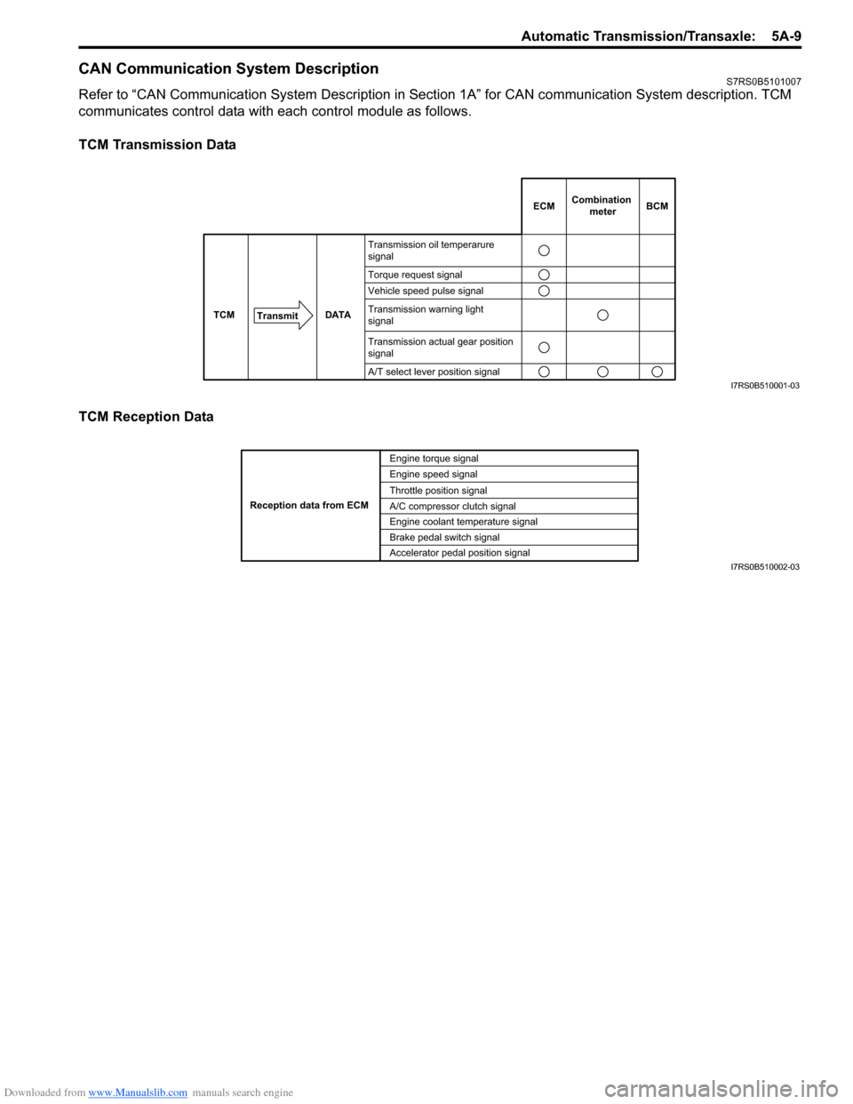
Refer to “CAN Communication System Description in Section 1A” for CAN communication System description. TCM
communicates control data with each control module as follows.
TCM Transmission Data
TCM Reception Data
DATA
TCM
Transmit
Transmission oil temperarure
signal
Torque request signal
Vehicle speed pulse signal
Transmission warning light
signal
Transmission actual gear position
signal
A/T select lever position signal
ECMCombination
meterBCM
I7RS0B510001-03
Engine torque signal
Engine speed signal
Throttle position signal
A/C compressor clutch signal
Engine coolant temperature signal
Brake pedal switch signal
Reception data from ECM
Accelerator pedal position signalI7RS0B510002-03
Page 654 of 1496
Downloaded from www.Manualslib.com manuals search engine 5A-10 Automatic Transmission/Transaxle:
Schematic and Routing Diagram
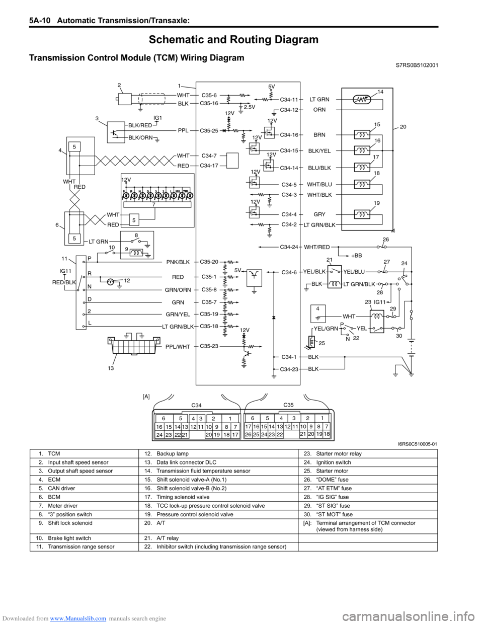
Transmission Control Module (TCM) Wiring DiagramS7RS0B5102001
IG1
115
5
5
8
9
10 7
P
R
N
D
2
L
12
12V 2.5V
5V
12V
5V
12V
12V
12V
12V
WHT
BLK
BLK
BLK
BLK
PPLBLK/RED
BLK/ORN
IG11
RED/BLK
YEL/BLKYEL/BLU
LT GRN/BLK
+BB
WHT/RED
14
20
15
16
17
19
12V18
1
2
3
4
6
13 21
26
24
27
28 29
30
WHT
WHT
RED
RED
WHT
RED
65
16 15 14 13 12 11 43
24 23 2122 10 9 8 721
1920 18 17
C34
17 16
26 25
15 14
65 3
42
13 12
23 2224 11 10 9
21 20 19 87
18
1
C35
[A]
22
25
YELYEL/GRN
WHT
P
N
BRN
LT GRN
ORN
BLK/YEL
BLU/BLK
GRY
LT GRN/BLK WHT/BLU
WHT/BLK
C34-11
C34-12
C34-16
C34-15
C34-14
C34-4
C34-2
C34-1
C34-23 C34-6
C34-24 C34-5
C34-3
RED
GRN
GRN/ORN PNK/BLK
GRN/YEL
LT GRN/BLKC35-6
C35-16
C35-23 C35-25
C35-20
C35-1
C35-8
C35-7
C35-19
C35-18 C34-17 C34-7
4IG11
12V
23
PPL/WHT
LT GRN
I6RS0C510005-01
1. TCM 12. Backup lamp 23. Starter motor relay
2. Input shaft speed sensor 13. Data link connector DLC 24. Ignition switch
3. Output shaft speed sensor 14. Transmission fluid temperature sensor 25. Starter motor
4. ECM 15. Shift solenoid valve-A (No.1) 26. “DOME” fuse
5. CAN driver 16. Shift solenoid valve-B (No.2) 27. “AT ETM” fuse
6. BCM 17. Timing solenoid valve 28. “IG SIG” fuse
7. Meter driver 18. TCC lock-up pressure control solenoid valve 29. “ST SIG” fuse
8. “3” position switch 19. Pressure control solenoid valve 30. “ST MOT” fuse
9. Shift lock solenoid 20. A/T [A]: Terminal arrangement of TCM connector
(viewed from harness side)
10. Brake light switch 21. A/T relay
11. Transmission range sensor 22. Inhibitor switch (including transmission range sensor)
Page 658 of 1496
Downloaded from www.Manualslib.com manuals search engine 5A-14 Automatic Transmission/Transaxle:
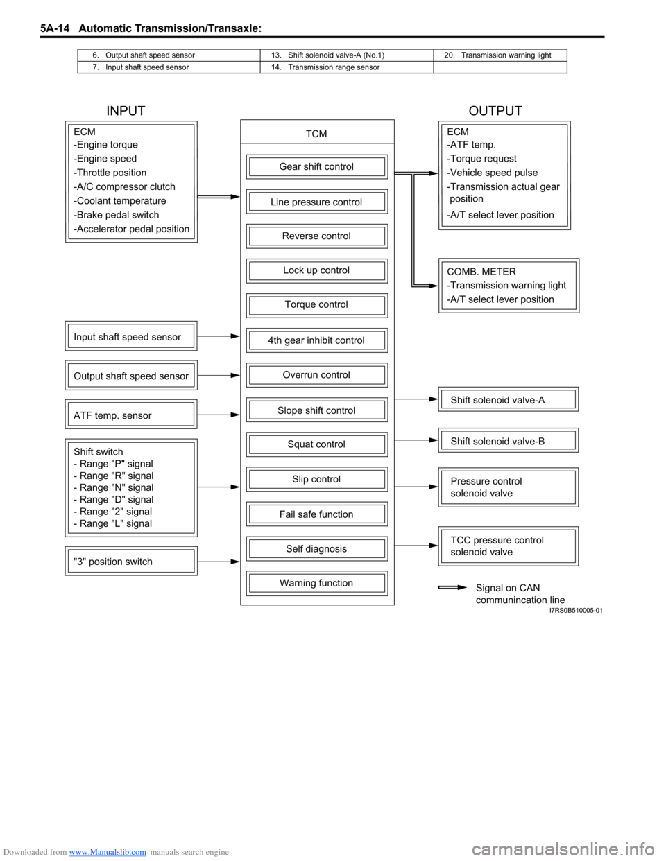
6. Output shaft speed sensor 13. Shift solenoid valve-A (No.1) 20. Transmission warning light
7. Input shaft speed sensor 14. Transmission range sensor
INPUT OUTPUT
TCMECM
Gear shift control
4th gear inhibit control
Slope shift control
Slip control
Lock up control
Torque control
Line pressure control
Overrun control
Reverse control
Squat control
Input shaft speed sensor
Output shaft speed sensor
"3" position switch ATF temp. sensor
Shift switch
- Range "P" signal
- Range "R" signal
- Range "N" signal
- Range "D" signal
- Range "2" signal
- Range "L" signal
Fail safe function
Self diagnosis
Warning function
ECM
Shift solenoid valve-A
Shift solenoid valve-B
TCC pressure control
solenoid valve
Pressure control
solenoid valve
Signal on CAN
communincation line
COMB. METER
-Engine torque
-Engine speed
-Throttle position
-A/C compressor clutch
-Coolant temperature
-Brake pedal switch -ATF temp.
-Torque request
-Vehicle speed pulse
-Transmission actual gear
position
-A/T select lever position
-Accelerator pedal position
-Transmission warning light
-A/T select lever position
I7RS0B510005-01
Page 662 of 1496

Downloaded from www.Manualslib.com manuals search engine 5A-18 Automatic Transmission/Transaxle:
Visual InspectionS7RS0B5104002
Visually check the following parts and systems.
Malfunction Indicator Lamp (MIL) CheckS7RS0B5104003
Refer to the same item in “Malfunction Indicator Lam p (MIL) Check in Section 1A” for checking procedure.
Transmission Warning Light CheckS7RS0B5104004
1) Turn ignition switch ON.
2) Check that transmission warning light lights for about 2 – 4 sec. and then goes OFF.
If anything faulty is found, advance “Transmission Warn ing Light Circuit Check – Light Does Not Come “ON” at
Ignition Switch ON” or “Transmission Warning Light Circu it Check – Light Remains “ON” at Ignition Switch ON”.
Inspection item Referring
• A/T fluid ----- level, leakage, color “Automatic Transaxle Fluid Level Inspection in Section 0B”
• A/T fluid hoses ----- disconnection, looseness, deterioration “A/T Fluid Cooler Hoses Replacement”
• A/T select cable ----- installation “S elect Cable Removal and Installation”
• Engine oil ----- level, leakage “Engine Oil and Filter Change in Section 0B”
• Engine coolant ----- level, leakage “Engine Coolant Change in Section 0B”
• Engine mountings ----- play, looseness, damage “Engine Assembly Removal and Installation in Section 1D”
• Suspension ----- play, looseness “Suspension, Wheels and Tires Symptom Diagnosis in Section 2A”
• Drive shafts ----- damage “Front Drive Shaft Assembly On-Vehicle Inspection in Section 3A”
• Battery ----- indicator condition, corrosion of terminal “Battery Inspection in Section 1J”
• Connectors of electric wire harness ----- disconnection, friction “Electronic Shift Control System Components
Location”
• Fuses ----- burning
• Parts ----- installation, damage
• Bolts ----- looseness
• Other parts that can be checked visually
Also check the following items at engine start, if possible.
• Transmission warning light (if equipped) ----- Operation “Transmission Warning Light Check”
• Malfunction indicator lamp ----- Operation “Malfunction Indicator Lamp (MIL) Check”
• Charge warning lamp ----- Operation “Generator Symptom Diagnosis in Section 1J”
• Engine oil pressure warning lamp ----- Operation “Oil Pressure Warning Ligh t Symptom Diagnosis in
Section 9C”
• Engine coolant temp. meter ----- Operation “Engine Coolant Temperature (ECT) Meter
Symptom Diagnosis in Section 9C”
• Other parts that can be checked visually
I4RS0A510008-01
Page 670 of 1496
Downloaded from www.Manualslib.com manuals search engine 5A-26 Automatic Transmission/Transaxle:
TRANSAXLE RANGE
Transaxle range detected by signal fed from
transmission range sensor.
D RANGE SIGNAL
ON: Signal which TCM require ECM to increase idle
speed
OFF: Signal which TCM does not require ECM to
increase idle speed
THROTTLE POSITION (%)
Throttle opening ratio computed by CAN signal from
ECM.
BRAKE SWITCH
Inputted signal from brake light switch on pedal bracket.
ON: Brake pedal depressed
OFF: Brake pedal released
TORQUE REDUCTION SIGNAL
ON: Signal which TCM require ECM to reduce output
torque at shifting gear
OFF: Signal which TCM does not require ECM to reduce
output torque
ENGINE COOLANT TEMPERATURE ( °C, °F)
Engine coolant temperature computed by CAN signal
from ECM. AIR CONDITIONER SIGNAL
ON: Signal which inform that air conditioner compressor
is turned ON.
OFF: Signal which inform that air conditioner
compressor is not turned ON.
ENGINE TORQUE SIGNAL (N
⋅m)
Engine torque computed by duty pulse signal outputted
from ECM.
SLIP RPM (RPM)
This parameter indicates slip ping rotation in the torque
converter (difference between input shaft rotation and
engine rotation)
MIL REQUEST
ON: Signal which TCM requires combination meter to
turn on malfunction indicator lamp.
OFF: Signal which TCM does not require combination
meter to turn on malf unction indicator lamp.
FUEL CUT FLAG
ON: Signal which inform that fuel cut is operating.
OFF: Signal which inform that fuel cut is not operating.
A/T Basic CheckS7RS0B5104010
This check is important for troubleshooting when TCM has detected no DTC and no abnormality has been noted in
“Visual Inspection”. Fo llow the flow carefully.
Step Action YesNo
1 Was “A/T System Check” preformed? Go to Step 2.Go to “A/T System
Check”.
2 Perform “Road Test”.
Is it OK? Go to Step 3.
Proceed to
“Troubleshooting” in
“Road Test”.
3 Perform “Manual Road Test”.
Is it OK? Go to Step 4.
Proceed to
“Troubleshooting” in
“Manual Road Test”.
4 Perform “Engine Brake Test”.
Is it OK? Go to Step 5.
Proceed to
“Troubleshooting” in
“Engine Brake Test”.
5 Perform “Stall Test”.
Is it OK? Go to Step 6.
Proceed to
“Troubleshooting” in
“Stall Test”.
6 Perform “Time Lag Test”.
Is it OK? Go to Step 7.
Proceed to
“Troubleshooting” in
“Time Lag Test”.
7 Perform “Line Pressure Test”.
Is it OK? Go to Step 8.
Proceed to
“Troubleshooting” in
“Line Pressure Test”.
8 Proceed to “Trouble Diag nosis 1” in “A/T Symptom
Diagnosis”.
Is trouble identified? Repair or replace faulty
parts.
Go to Step 9.
Page 674 of 1496
Downloaded from www.Manualslib.com manuals search engine 5A-30 Automatic Transmission/Transaxle:
Troubleshooting
Engine Brake TestS7RS0B5104013
WARNING!
Before test, make sure that there is no vehicle behind so as to prevent rear-end collision.
1) While driving vehicle in 3rd gear of “D” range, shift select lever down to “2” range and check if engine brake
operates.
2) In the same way as in Step 1), check engine brake for operation when select lever is shifted down to “L” range.
3) Engine brake should operate in the test.
Troubleshooting
Stall TestS7RS0B5104014
This test is to check overall performance of automatic tr ansaxle and engine by measuring stall speed at “D” and “R”
ranges. Be sure to perform this test only when transaxle fluid is at normal operating temperature and its level is
between FULL and LOW marks.
CAUTION!
• Do not run engine at stall more than 5 seconds continuously, or fluid temperature may rise excessively high.
• After performing stall test, be su re to leave engine running at idle for longer than 1 minute before
another stall test.
1) Apply parking brake and block wheels.
2) Install tachometer.
3) Start engine with select lever shifted to “P” range.
4) Depress brake pedal fully.
5) Shift select lever to “D” range and depress accelerator pedal fully while watching tachometer. Read engine rpm quickly when it has become constant (stall speed).
6) Release accelerator pedal immediately after stall speed is checked.
7) In the same way, check stall speed in “R” range.
8) Stall speed should be withi n the following specification.
Engine stall speed
Standard: 2100 – 2400 rpm Condition Possible cause Correction / Reference Item
Operated gear is not
correct Faulty valve body component
Replace valve body assembly.
Faulty clutch or brake Inspect clutch and brake. If any parts are faulty,
replace them.
Condition Possible cause Correction / Reference Item
Failure to operate when
shifted down to “2” range Faulty valve body component
Replace valve body assembly.
Faulty O/D and 2nd coast brake Inspect. If NG, replace.
Failure to operate when
shifted down to “L” range Faulty valve body component
Replace valve body assembly.
Faulty 1st and reverse brake Inspect. If NG, replace.
Page 687 of 1496
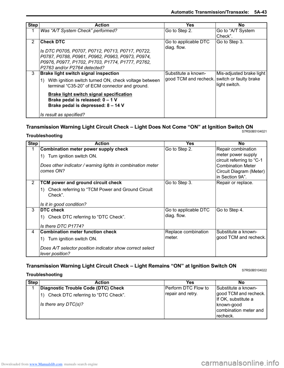
Downloaded from www.Manualslib.com manuals search engine Automatic Transmission/Transaxle: 5A-43
Transmission Warning Light Circuit Check – Light Does Not Come “ON” at Ignition Switch ONS7RS0B5104021
Troubleshooting
Transmission Warning Light Circuit Check – Light Remains “ON” at Ignition Switch ONS7RS0B5104022
TroubleshootingStep Action Yes No
1 Was “A/T System Check” performed? Go to Step 2. Go to “A/T System
Check”.
2 Check DTC
Is DTC P0705, P0707, P0712, P0713, P0717, P0722,
P0787, P0788, P0961, P0962, P0963, P0973, P0974,
P0976, P0977, P1702, P1703, P1774, P1777, P2762,
P2763 and/or P2764 detected? Go to applicable DTC
diag. flow.
Go to Step 3.
3 Brake light switch signal inspection
1) With ignition switch turned ON, check voltage between
terminal “C35-20” of ECM connector and ground.
Brake light switch signal specification
Brake pedal is released: 0 – 1 V
Brake pedal is depressed: 8 – 14 V
Is result as specified? Substitute a known-
good TCM and recheck.
Mis-adjusted brake light
switch or faulty brake
light switch.
Step
Action YesNo
1 Combination meter power supply check
1) Turn ignition switch ON.
Does other indicator / warnin g lights in combination meter
comes ON? Go to Step 2.
Repair combination
meter power supply
circuit referring to “C-1
Combination Meter
Circuit Diagram (Meter)
in Section 9A”.
2 TCM power and ground circuit check
1) Check referring to “TCM Power and Ground Circuit
Check”.
Is it in good condition? Go to Step 3.
Repair or replace.
3 DTC check
1) Check DTC referring to “DTC Check”.
Is there DTC P1774? Go to applicable DTC
diag. flow.
Go to Step 4.
4 Combination meter function check
1) Turn ignition switch ON.
Does A/T selector position in dicator show correct select
lever position? Replace combination
meter.
Substitute a known-
good TCM and recheck.
Step
Action YesNo
1 Diagnostic Trouble Code (DTC) Check
1) Check DTC referring to “DTC Check”.
Is there any DTC(s)? Perform DTC Flow to
repair and retry.
Substitute a known-
good TCM and recheck.
If OK, substitute a
known-good
combination meter and
recheck.