back SUZUKI SWIFT 2007 2.G Service Workshop Manual
[x] Cancel search | Manufacturer: SUZUKI, Model Year: 2007, Model line: SWIFT, Model: SUZUKI SWIFT 2007 2.GPages: 1496, PDF Size: 34.44 MB
Page 1365 of 1496
Downloaded from www.Manualslib.com manuals search engine Seats: 9G-3
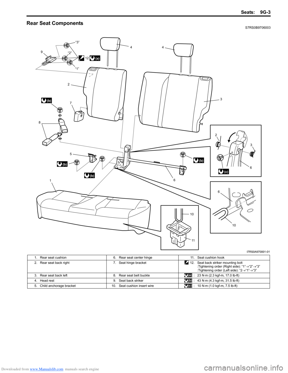
Rear Seat ComponentsS7RS0B9706003
1
5
(b)
(b)
(b)
8
7
9
2
4
4
3
(b)
6
6(c)
2
3
10
6
(a)
10
11
12
“1”
“2”
“3”
I7RS0A970001-01
1. Rear seat cushion
6. Rear seat center hinge11. Seat cushion hook
2. Rear seat back right 7. Seat hinge bracket12. Seat back striker mounting bolt
:Tightening order (Right side): “1” →“2” →“3”
:Tightening order (Left side): “2 →“1” →“3”
3. Rear seat back left 8. Rear seat belt buckle : 23 N⋅m (2.3 kgf-m, 17.0 lb-ft)
4. Head rest 9. Seat back striker : 43 N⋅m (4.3 kgf-m, 31.5 lb-ft)
5. Child anchorage bracket 10. Seat cushion insert wire : 10 N⋅m (1.0 kgf-m, 7.5 lb-ft)
Page 1366 of 1496
Downloaded from www.Manualslib.com manuals search engine 9G-4 Seats:
Rear Seat Removal and InstallationS7RS0B9706004
Removal1) Fold rear seat back forward.
2) Remove seat mounting bolts and nuts to remove seat assembly.
3) Disassemble and repair seat as necessary.
Installation
Reverse removal procedure to install rear seat.
• Tighten seat back striker mounting bolts according to “Rear Seat Components”.
• Torque to specifications in “Rear Seat Components”.
• When installing seat cushion, align seat cushion hook with center hinge bracket.
Specifications
Tightening Torque SpecificationsS7RS0B9707001
NOTE
The specified tightening torque is also described in the following.
“Front Seat Components”
“Rear Seat Components”
Reference:
For the tightening torque of fastener not specified in this section, refer to “Fasteners Information in Section 0A”.
Special Tools and Equipment
Recommended Service MaterialS7RS0B9708001
NOTE
Required service material is also described in the following.
“Front Seat Components”
Material SUZUKI recommended product or Specification Note
Thread lock cement Thread Lock Cement Super 1303B P/No.: 99000–32030 �)
Thread Lock Cement 1305 P/No.: 99000–32100 �)
Page 1381 of 1496
Downloaded from www.Manualslib.com manuals search engine Body Structure: 9K-4
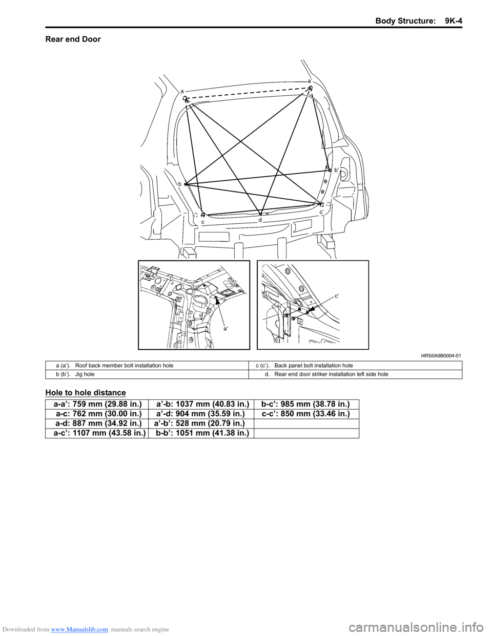
Rear end Door
Hole to hole distance
I4RS0A9B0004-01
a (a’). Roof back member bolt installation holec (c’). Back panel bolt installation hole
b (b’). Jig hole d. Rear end door striker installation left side hole
a-a’: 759 mm (29.88 in.) a’-b: 1037 mm (40.83 in.) b-c’: 985 mm (38.78 in.)
a-c: 762 mm (30.00 in.) a’-d: 904 mm (35.59 in.) c-c’: 850 mm (33.46 in.)
a-d: 887 mm (34.92 in.) a’-b’: 528 mm (20.79 in.)
a-c’: 1107 mm (43.58 in.) b-b’: 1051 mm (41.38 in.)
Page 1389 of 1496
Downloaded from www.Manualslib.com manuals search engine Paint / Coatings: 9L-2
Plastic Parts FinishingS7RS0B9C01002
Paintable plastic parts are ABS plastic parts.
Painting
Rigid or hand ABS plastic needs no primer coating.
General acrylic lacquers can be painted properly over hard ABS plastic in terms of adherence.
1) Use cleaning solvent for paint finish to wash each part.
2) Apply conventional acrylic color lacquer to part surface.
3) Follow lacquer directions for required drying time. (Proper drying temperature range is 60 – 70 °C (140 – 158 ° F)).
Reference
Plastic parts employ not only ABS (Acrylonitrile Butadiene Styrene) plastic but also polypro pylene, vinyl, or the like
plastic. Burning test method to iden tify ABS plastic is described below.
1) Use a sharp blade to cut off a plastic sliver from the part at its hidden backside.
2) Hold sliver with pincer s and set it on fire.
3) Carefully observe condition of the burning plastic.
4) ABS plastic must raise readily dist inguishable back smoke while burning with its residue suspended in air
temporarily.
5) Polypropylene must raise no readily distinguishable smoke while burning.
Page 1405 of 1496
Downloaded from www.Manualslib.com manuals search engine Body Electrical Control System: 10B-2
CAN Communication System DescriptionS7RS0BA201002
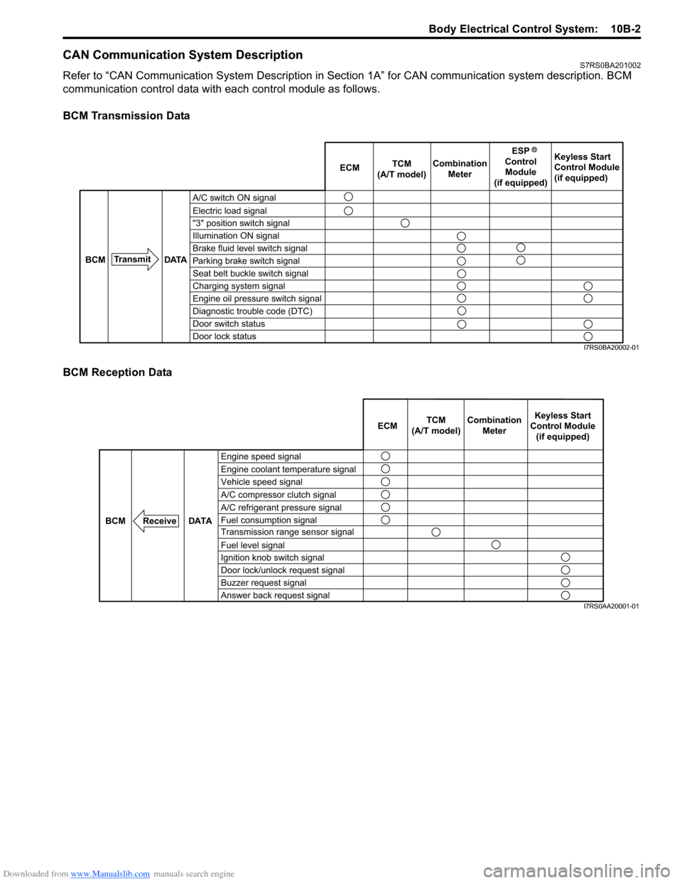
Refer to “CAN Communication System Description in Section 1A” for CAN communication system description. BCM
communication control data with ea ch control module as follows.
BCM Transmission Data
BCM Reception Data
A/C switch ON signal
Electric load signal
"3" position switch signal
Illumination ON signal
Brake fluid level switch signal
Parking brake switch signal
Seat belt buckle switch signal
Charging system signal
Engine oil pressure switch signal
Diagnostic trouble code (DTC)
Door switch status
Door lock status ECM
TCM
(A/T model) Combination
Meter Keyless Start
Control Module
(if equipped)
Transmit DATA
BCM
ESP
Control Module
(if equipped)
I7RS0BA20002-01
Engine speed signal
Vehicle speed signal Engine coolant temperature signal
A/C refrigerant pressure signal
Fuel consumption signal A/C compressor clutch signal
Transmission range sensor signal
Fuel level signal
Ignition knob switch signal
Door lock/unlock request signal
Buzzer request signal
Answer back request signal
DATA
BCM
Receive
Combination
Meter
TCM
(A/T model) Keyless Start
Control Module (if equipped)
ECM
I7RS0AA20001-01
Page 1437 of 1496
Downloaded from www.Manualslib.com manuals search engine Body Electrical Control System: 10B-34
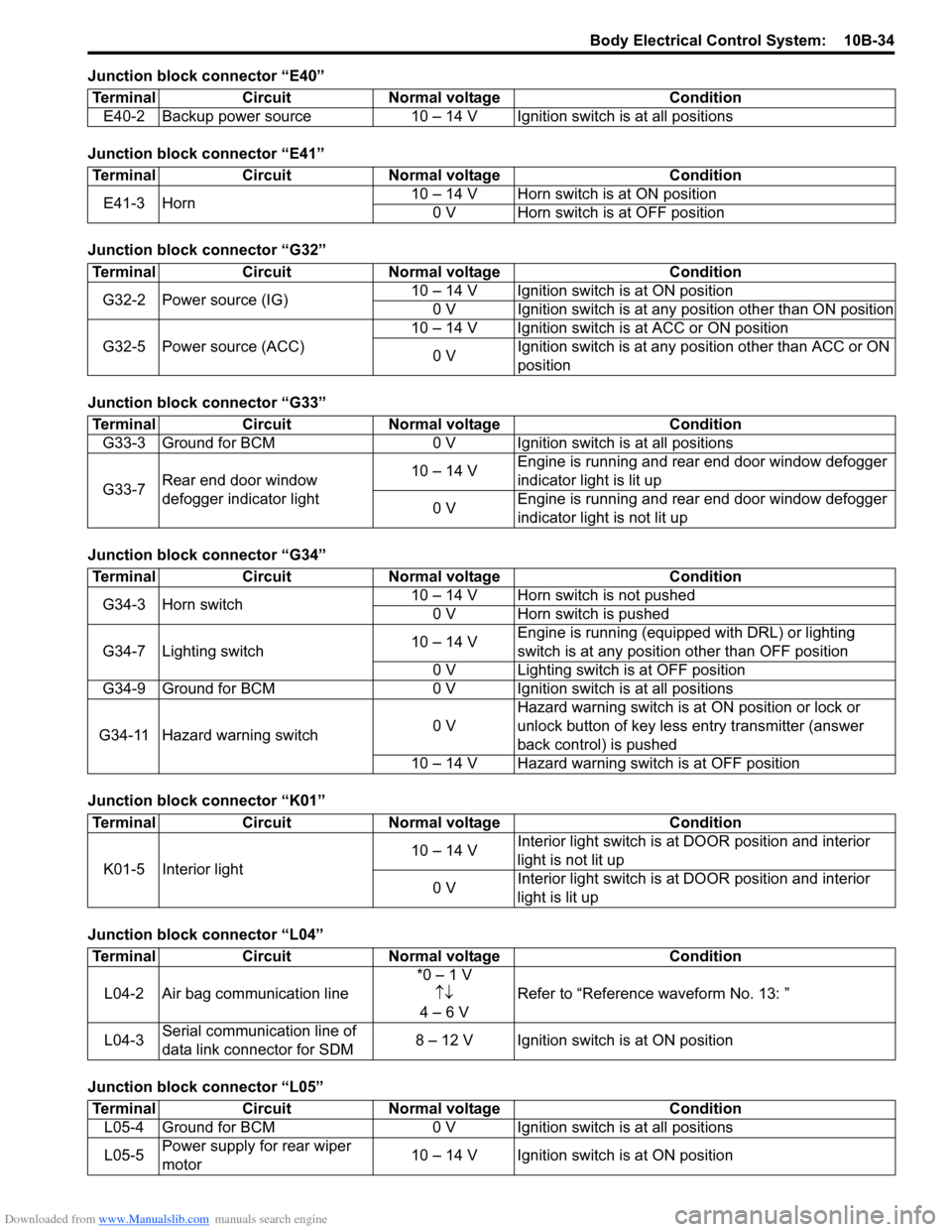
Junction block connector “E40”
Junction block connector “E41”
Junction block connector “G32”
Junction block connector “G33”
Junction block connector “G34”
Junction block connector “K01”
Junction block connector “L04”
Junction block connector “L05”Terminal Circuit Normal voltage Condition
E40-2 Backup power source 10 – 14 V Igni tion switch is at all positions
TerminalCircuitNormal voltage Condition
E41-3 Horn 10 – 14 V Horn switch is at ON position
0 V Horn switch is at OFF position
Terminal CircuitNormal voltage Condition
G32-2 Power source (IG) 10 – 14 V Ignition switch is at ON position
0 V Ignition switch is at any position other than ON position
G32-5 Power source (ACC) 10 – 14 V Ignition switch is at ACC or ON position
0 V Ignition switch is at any position other than ACC or ON
position
Terminal
CircuitNormal voltage Condition
G33-3 Ground for BCM 0 V Ignition switch is at all positions
G33-7 Rear end door window
defogger indicator light 10 – 14 V
Engine is running and rear end door window defogger
indicator light is lit up
0 V Engine is running and rear end door window defogger
indicator light is not lit up
Terminal
CircuitNormal voltage Condition
G34-3 Horn switch 10 – 14 V Horn switch is not pushed
0 V Horn switch is pushed
G34-7 Lighting switch 10 – 14 VEngine is running (equipped with DRL) or lighting
switch is at any position other than OFF position
0 V Lighting switch is at OFF position
G34-9 Ground for BCM 0 V Ignition switch is at all positions
G34-11 Hazard warning switch 0 VHazard warning switch is at
ON position or lock or
unlock button of key less entry transmitter (answer
back control) is pushed
10 – 14 V Hazard warning switch is at OFF position
Terminal CircuitNormal voltage Condition
K01-5 Interior light 10 – 14 V
Interior light switch is at
DOOR position and interior
light is not lit up
0 V Interior light switch is at
DOOR position and interior
light is lit up
Terminal CircuitNormal voltage Condition
L04-2 Air bag communication line *0 – 1 V
↑↓
4 – 6 V Refer to “Reference
waveform No. 13: ”
L04-3 Serial communication line of
data link connector for SDM 8 – 12 V Ignition switch is at ON position
Terminal
CircuitNormal voltage Condition
L05-4 Ground for BCM 0 V Ignition switch is at all positions
L05-5 Power supply for rear wiper
motor 10 – 14 V Ignition switch is at ON position
Page 1443 of 1496
Downloaded from www.Manualslib.com manuals search engine Body Electrical Control System: 10B-40
Special Tools and Equipment
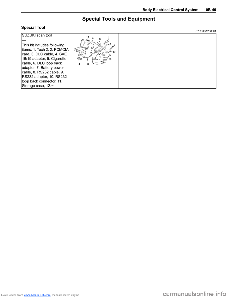
Special ToolS7RS0BA208001
SUZUKI scan tool
—
This kit includes following
items. 1. Tech 2, 2. PCMCIA
card, 3. DLC cable, 4. SAE
16/19 adapter, 5. Cigarette
cable, 6. DLC loop back
adapter, 7. Battery power
cable, 8. RS232 cable, 9.
RS232 adapter, 10. RS232
loop back connector, 11.
Storage case, 12.�)
Page 1462 of 1496
Downloaded from www.Manualslib.com manuals search engine 10C-19 Immobilizer Control System:
Special Tools and Equipment
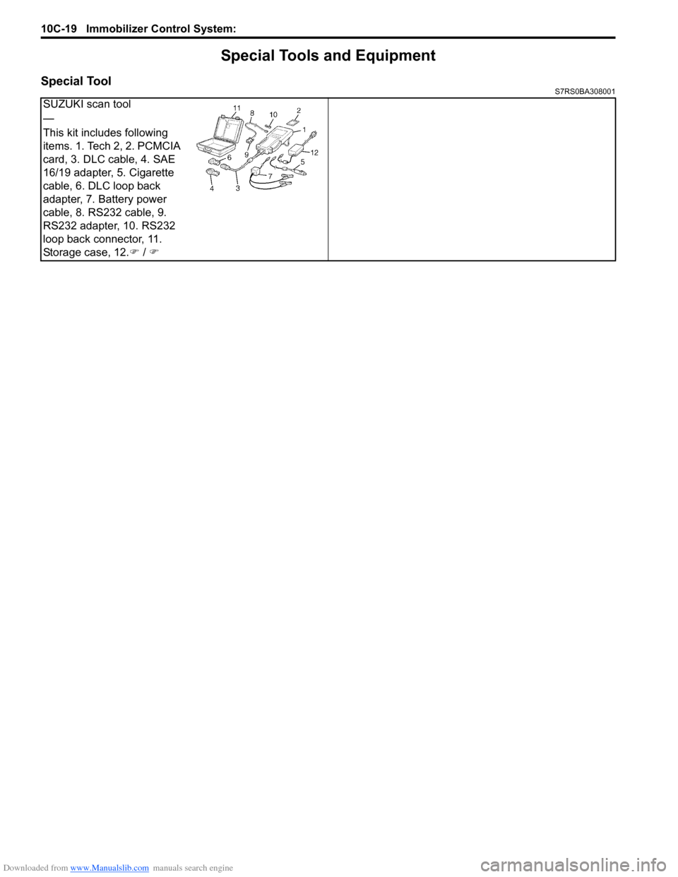
Special ToolS7RS0BA308001
SUZUKI scan tool
—
This kit includes following
items. 1. Tech 2, 2. PCMCIA
card, 3. DLC cable, 4. SAE
16/19 adapter, 5. Cigarette
cable, 6. DLC loop back
adapter, 7. Battery power
cable, 8. RS232 cable, 9.
RS232 adapter, 10. RS232
loop back connector, 11.
Storage case, 12.�) / �)
Page 1464 of 1496
Downloaded from www.Manualslib.com manuals search engine 10E-2 Keyless Start System:
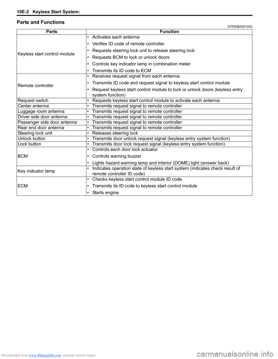
Parts and FunctionsS7RS0BA501002
PartsFunction
Keyless start control module • Activates each antenna
• Verifies ID code of remote controller
• Requests steering lock unit to release steering lock
• Requests BCM to lock or unlock doors
• Controls key indicator la
mp in combination meter
• Transmits its ID code to ECM
Remote controller • Receives request signal from each antenna
• Transmits ID code and request signal to keyless start control module
• Request keyless start control module to lock or unlock doors (keyless entry
system function)
Request switch • Requests keyless start control module to activate each antenna
Center antenna • Transmits request signal to remote controller
Luggage room antenna • Transmits request signal to remote controller
Driver side door antenna • Transmits request signal to remote controller
Passenger side door antenna • Transmits request signal to remote controller
Rear end door antenna • Transmits request signal to remote controller
Steering lock unit • Releases steering lock
Unlock button • Transmits door unlock request signal (keyless entry system function)
Lock button • Transmits door lock request signal (keyless entry system function)
BCM • Controls each door lock actuator
• Controls warning buzzer
• Lights hazard warning lamp and interior (DOME) light (answer back)
Key indicator lamp • Indicates operation state of keyless start system (indicates check result of
remote controller ID code)
ECM • Checks keyless start control module ID code
• Transmits its ID code to keyless start control module
• Starts engine
Page 1468 of 1496
Downloaded from www.Manualslib.com manuals search engine 10E-6 Keyless Start System:
Alarm FunctionS7RS0BA501006
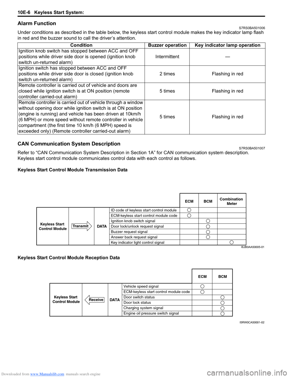
Under conditions as described in the table below, the keyless start control module makes the key indicator lamp flash
in red and the buzzer sound to call the driver’s attention.
CAN Communication System DescriptionS7RS0BA501007
Refer to “CAN Communication System Description in Section 1A” for CAN communication system description.
Keyless start control module communicates control data wit h each control as follows.
Keyless Start Control Module Transmission Data
Keyless Start Control Module Reception Data Condition Buzzer operation Key indicator lamp operation
Ignition knob switch has stopped between ACC and OFF
positions while driver side door is opened (ignition knob
switch un-returned alarm) Intermittent —
Ignition switch has stopped between ACC and OFF
positions while driver side door is closed (ignition knob
switch un-returned alarm) 2 times Flashing in red
Remote controller is carried out of vehicle and doors are
closed while ignition switch is at ON position (remote
controller carried-out alarm) 5 times Flashing in red
Remote controller is carried out of vehicle through a window
without opening door while ignition switch is at ON position
(engine is running) and vehicle has been driven at 10km/h
(6 MPH) or more speed without remote controller in vehicle
compartment (the first time 10 km/h (6 MPH) speed is
exceeded only) (Remote cont roller carried-out alarm) 5 times Flashing in red
BCM
ECM Combination
Meter
ID code of keyless start control module
ECM-keyless start control module code
Ignition knob switch signal
Door lock/unlock request signal
Buzzer request signal
Answer back request signal
Key indicator light control signal
DATA
Transmit
Keyless Start
Control Module
I6JB0AA50005-01
Vehicle speed signal
ECM-keyless start control module code
Door switch status
Door lock status
Charging system signal
Engine oil pressure switch signal ECM BCM
DATA
ReceiveKeyless Start
Control Module
I5RW0CA50001-02