assembly removal SUZUKI SWIFT 2007 2.G Service Workshop Manual
[x] Cancel search | Manufacturer: SUZUKI, Model Year: 2007, Model line: SWIFT, Model: SUZUKI SWIFT 2007 2.GPages: 1496, PDF Size: 34.44 MB
Page 970 of 1496
Downloaded from www.Manualslib.com manuals search engine 7B-22 Air Conditioning System: Manual Type
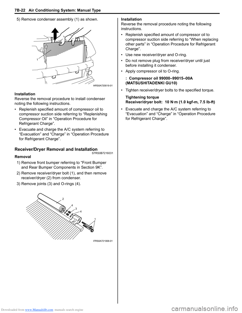
5) Remove condenser assembly (1) as shown.
Installation
Reverse the removal procedure to install condenser
noting the following instructions.
• Replenish specified amount of compressor oil to compressor suction side referring to “Replenishing
Compressor Oil” in “Operation Procedure for
Refrigerant Charge”.
• Evacuate and charge the A/C system referring to “Evacuation” and “Charge” in “Operation Procedure
for Refrigerant Charge”.
Receiver/Dryer Removal and InstallationS7RS0B7216031
Removal
1) Remove front bumper referring to “Front Bumper and Rear Bumper Components in Section 9K”.
2) Remove receiver/dryer bolt (1), and then remove receiver/dryer (2) from condenser.
3) Remove joints (3) and O-rings (4). Installation
Reverse the removal procedure noting the following
instructions.
• Replenish specified amount of compressor oil to
compressor suction side referring to “When replacing
other parts” in “Operation Procedure for Refrigerant
Charge”.
• Use new receiver/dryer and O-ring.
• Do not remove plug from receiver/dryer until just before installin g it condenser.
• Apply compressor oil to O-ring.
: Compressor oil 99000–99015–00A
(MATSUSHITADENKI GU10)
• Tighten receiver/dryer bolts to the specified torque. Tightening torque
Receiver/dryer bolt: 10 N· m (1.0 kgf-m, 7.5 lb-ft)
• Evacuate and charge the A/C system referring to “Evacuation” and “Charge” in “Operation Procedure
for Refrigerant Charge”.
1
I4RS0A720018-01
1
4
4
3
2
I7RS0A721008-01
Page 972 of 1496

Downloaded from www.Manualslib.com manuals search engine 7B-24 Air Conditioning System: Manual Type
HVAC Unit Removal and InstallationS7RS0B7216006
Removal1) Disconnect negative (–) cable from battery.
2) Disable air bag system referring to “Disabling Air Bag System in Section 8B”.
3) Recover refrigerant from A/C system with recovery and recycling equipment referring to “Recovery” in
“Operation Procedure for Refrigerant Charge”.
4) Remove cowl top panel referring to “Cowl Top Components in Section 9K”.
5) Drain engine coolant, and then disconnect heater hoses (1) from HVAC unit (2).
6) Remove instrument panel from vehicle body referring to “Audio Unit Re moval and Installation in
Section 9C”.
7) Loosen suction hose and liquid pipe bolt (4).
8) Remove nuts (3).
9) Remove HVAC unit from vehicle body. Installation
Reverse removal procedure noting the following
instructions.
• Replenish specified amount of compressor oil to
compressor suction side referring to “Replenishing
Compressor Oil” in “Operation Procedure for
Refrigerant Charge”.
• Install the padding (1) to the installation hole uniformly.
• Evacuate and charge the A/C system referring to “Evacuation” and “Charge” in “Operation Procedure
for Refrigerant Charge”.
• Adjust control cables referr ing to “HVAC Control Unit
Removal and Installati on in Section 7A”.
• Enable air bag system referring to “Enabling Air Bag System in Section 8B”.
Evaporator InspectionS7RS0B7216007
Check the followings.
• Clog of A/C evaporator fins.If any clogs are found, A/C evaporator fins should be
washed with water, and then should be dried with
compressed air.
• A/C evaporator fins for leakage and breakage. If any defects are found, repair or replace A/C
evaporator.
• A/C evaporator fittings for leakage. If any defects are found, repair or replace A/C
evaporator.
2. Blower upper case 8. Temperature control door assembly 14. Temperature control lever 20. Packing
3. Air intake control actuator 9. Blower motor resistor 15. Airflow control lever21. Filter cover (if equipped)
4. HVAC Air filter (if equipped) 10. Blower lower case 16. Evaporator22. Drain hose
5. Heater unit upper case 11. Blower motor 17. O-ring23. Cable lock clamp
6. Foot duct 12. Heater unit lower case 18. Expansion valve: Do not reuse.
3
2
3
3
1
4
I4RS0B720009-01
1
I4RS0B720010-01
Page 976 of 1496
Downloaded from www.Manualslib.com manuals search engine 7B-28 Air Conditioning System: Manual Type
Compressor Drive Belt Removal and
Installation
S7RS0B7216017
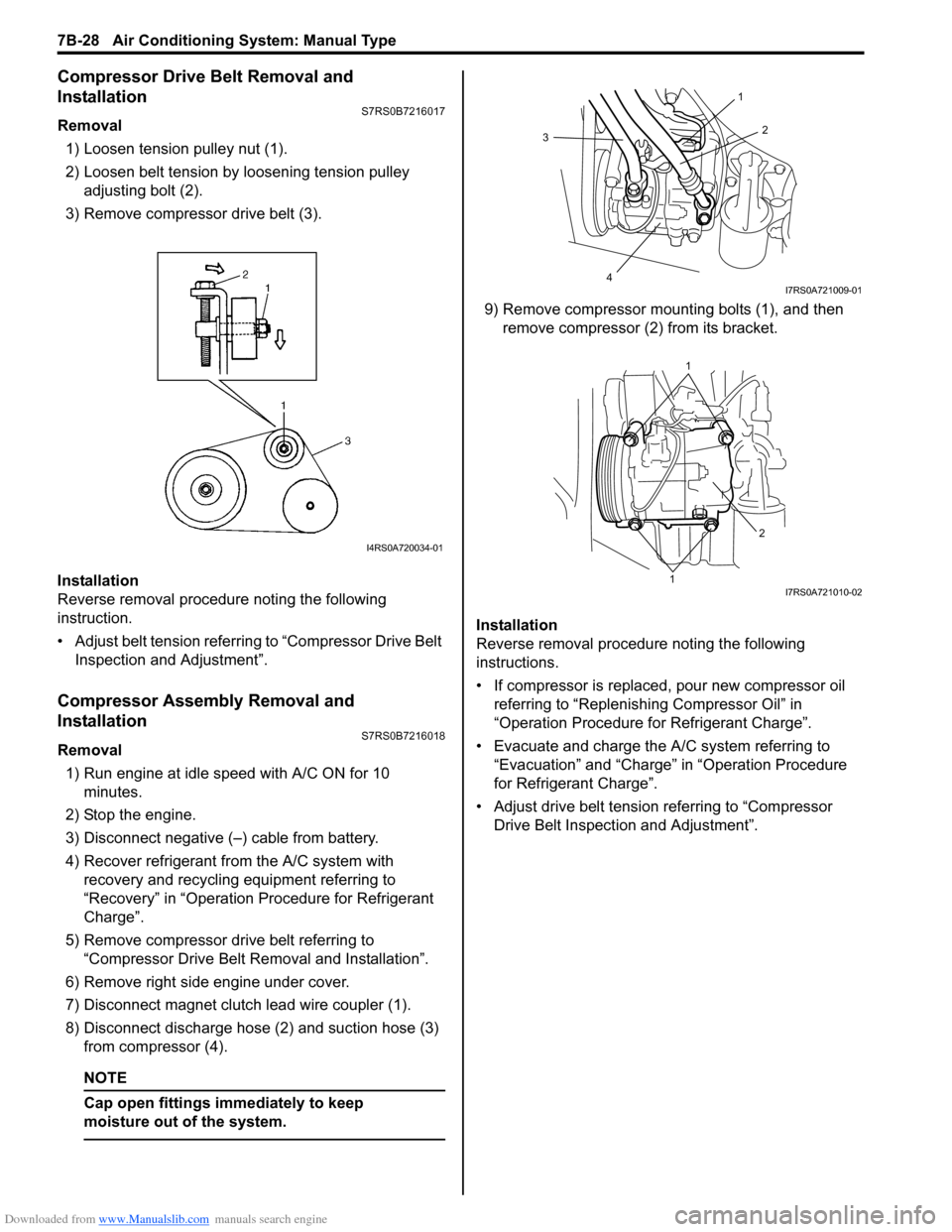
Removal1) Loosen tension pulley nut (1).
2) Loosen belt tension by loosening tension pulley adjusting bolt (2).
3) Remove compressor drive belt (3).
Installation
Reverse removal procedure noting the following
instruction.
• Adjust belt tension referring to “Compressor Drive Belt Inspection and Adjustment”.
Compressor Assembly Removal and
Installation
S7RS0B7216018
Removal
1) Run engine at idle speed with A/C ON for 10 minutes.
2) Stop the engine.
3) Disconnect negative (–) cable from battery.
4) Recover refrigerant fr om the A/C system with
recovery and recycling equipment referring to
“Recovery” in “Operation Procedure for Refrigerant
Charge”.
5) Remove compressor drive belt referring to “Compressor Drive Belt Re moval and Installation”.
6) Remove right side engine under cover.
7) Disconnect magnet clutch lead wire coupler (1).
8) Disconnect discharge hose (2) and suction hose (3) from compressor (4).
NOTE
Cap open fittings immediately to keep
moisture out of the system.
9) Remove compressor mounting bolts (1), and then remove compressor (2 ) from its bracket.
Installation
Reverse removal procedure noting the following
instructions.
• If compressor is replaced, pour new compressor oil referring to “Replenishi ng Compressor Oil” in
“Operation Procedure for Refrigerant Charge”.
• Evacuate and charge the A/C system referring to “Evacuation” and “Charge” in “Operation Procedure
for Refrigerant Charge”.
• Adjust drive belt tension referring to “Compressor Drive Belt Inspecti on and Adjustment”.
I4RS0A720034-01
3
4 2
1
I7RS0A721009-01
1
1 2
I7RS0A721010-02
Page 977 of 1496
Downloaded from www.Manualslib.com manuals search engine Air Conditioning System: Manual Type 7B-29
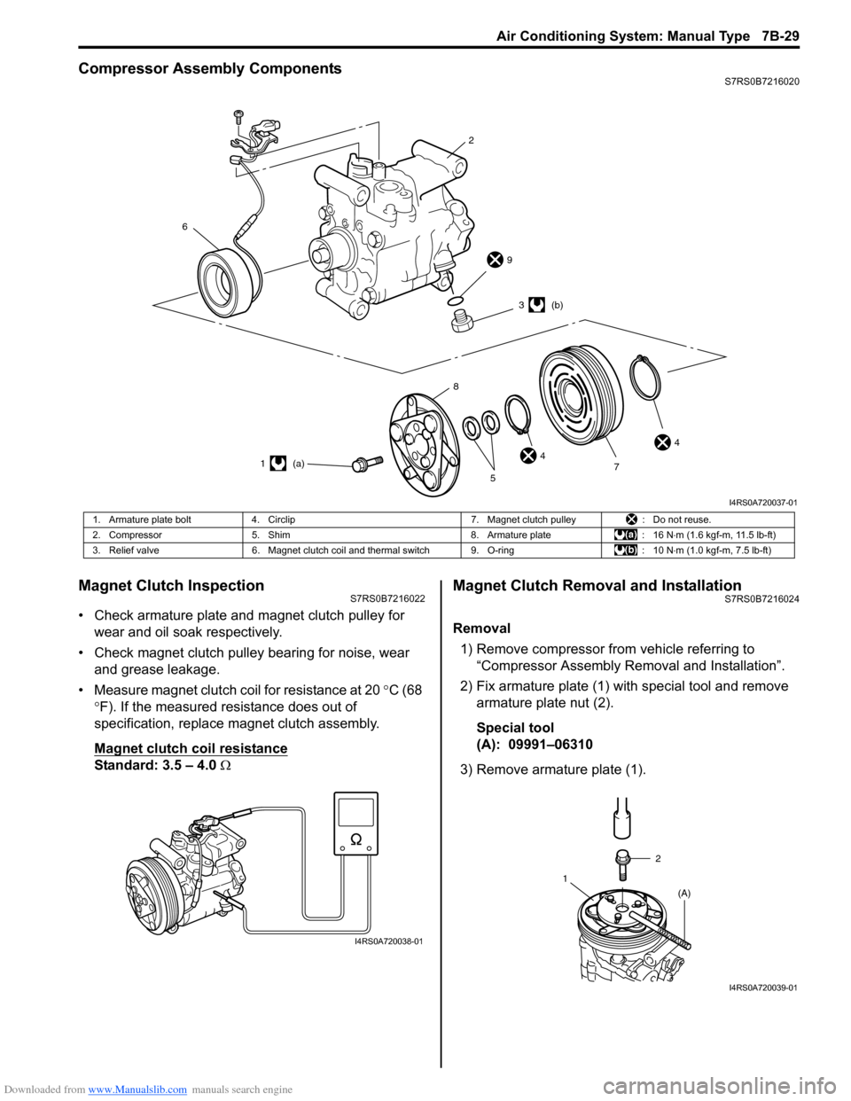
Compressor Assembly ComponentsS7RS0B7216020
Magnet Clutch InspectionS7RS0B7216022
• Check armature plate and magnet clutch pulley for wear and oil soak respectively.
• Check magnet clutch pulley bearing for noise, wear and grease leakage.
• Measure magnet clutch coil for resistance at 20 °C (68
° F). If the measured resistance does out of
specification, replace magnet clutch assembly.
Magnet clutch coil resistance
Standard: 3.5 – 4.0 Ω
Magnet Clutch Removal and InstallationS7RS0B7216024
Removal
1) Remove compressor from vehicle referring to “Compressor Assembly Re moval and Installation”.
2) Fix armature plate (1) with special tool and remove armature plate nut (2).
Special tool
(A): 09991–06310
3) Remove armature plate (1).
6
2
9
44
3 (b)
1 (a) 7
5
8
I4RS0A720037-01
1. Armature plate bolt
4. Circlip 7. Magnet clutch pulley: Do not reuse.
2. Compressor 5. Shim 8. Armature plate: 16 N⋅m (1.6 kgf-m, 11.5 lb-ft)
3. Relief valve 6. Magnet clutch coil and thermal switch 9. O-ring : 10 N⋅m (1.0 kgf-m, 7.5 lb-ft)
I4RS0A720038-01
2
1 (A)
I4RS0A720039-01
Page 980 of 1496
Downloaded from www.Manualslib.com manuals search engine 7B-32 Air Conditioning System: Manual Type
Relief Valve Removal and InstallationS7RS0B7216030
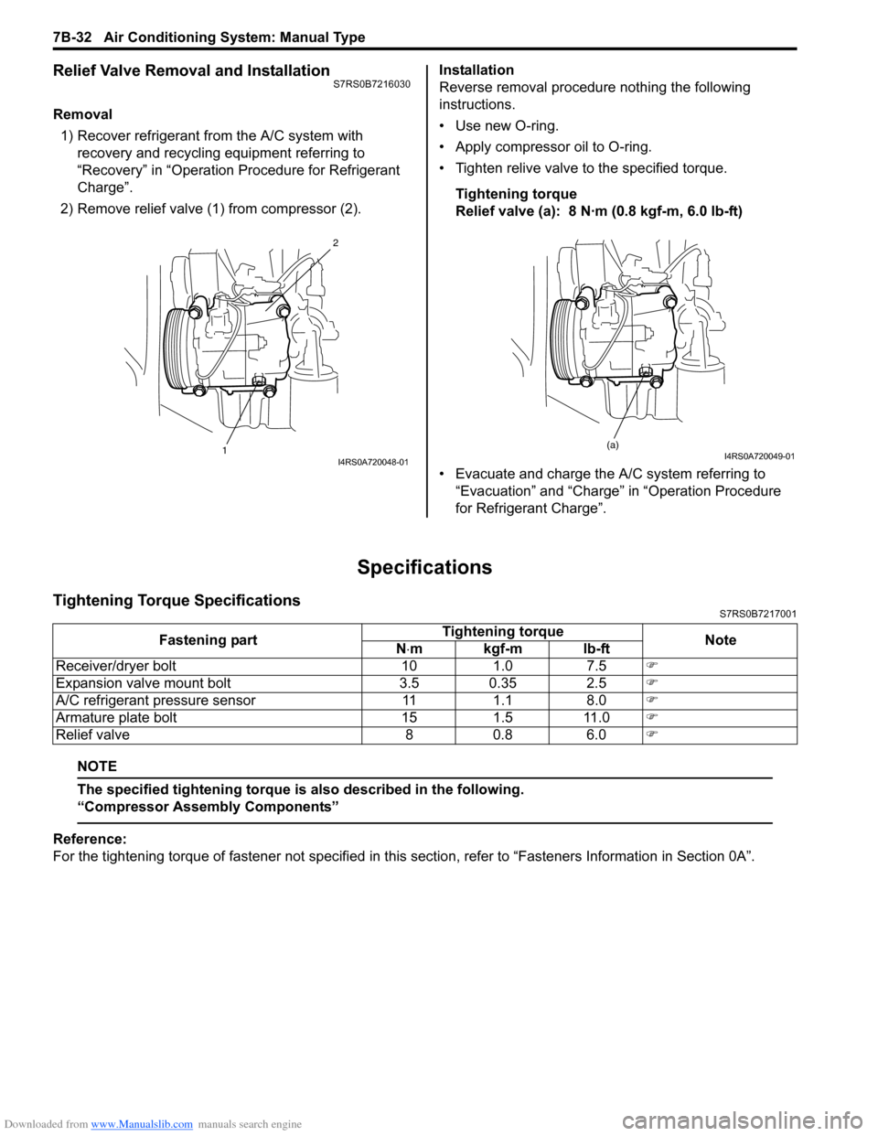
Removal1) Recover refrigerant fr om the A/C system with
recovery and recycling equipment referring to
“Recovery” in “Operation Procedure for Refrigerant
Charge”.
2) Remove relief valve (1) from compressor (2). Installation
Reverse removal procedure nothing the following
instructions.
• Use new O-ring.
• Apply compressor oil to O-ring.
• Tighten relive valve to the specified torque.
Tightening torque
Relief valve (a): 8 N·m (0.8 kgf-m, 6.0 lb-ft)
• Evacuate and charge the A/C system referring to “Evacuation” and “Charge” in “Operation Procedure
for Refrigerant Charge”.
Specifications
Tightening Torque SpecificationsS7RS0B7217001
NOTE
The specified tightening torque is also described in the following.
“Compressor Assembly Components”
Reference:
For the tightening torque of fastener not specified in this section, refer to “Fasteners Information in Section 0A”.
12I4RS0A720048-01
(a)I4RS0A720049-01
Fastening part
Tightening torque
Note
N ⋅mkgf-mlb-ft
Receiver/dryer bolt 10 1.0 7.5 �)
Expansion valve mount bolt 3.5 0.35 2.5 �)
A/C refrigerant pressure sensor 11 1.1 8.0 �)
Armature plate bolt 15 1.5 11.0 �)
Relief valve 8 0.8 6.0 �)
Page 1021 of 1496
Downloaded from www.Manualslib.com manuals search engine Air Conditioning System: Automatic Type 7B-73
HVAC Unit Removal and InstallationS7RS0B7226003
Refer to “HVAC Unit Removal and Installation”.
Temperature Control Actuator Removal and
Installation
S7RS0B7226004
Removal1) Disconnect negative (–) cable at battery.
2) Remove steering column hol e cover from instrument
panel.
3) Remove foot duct from HVAC unit.
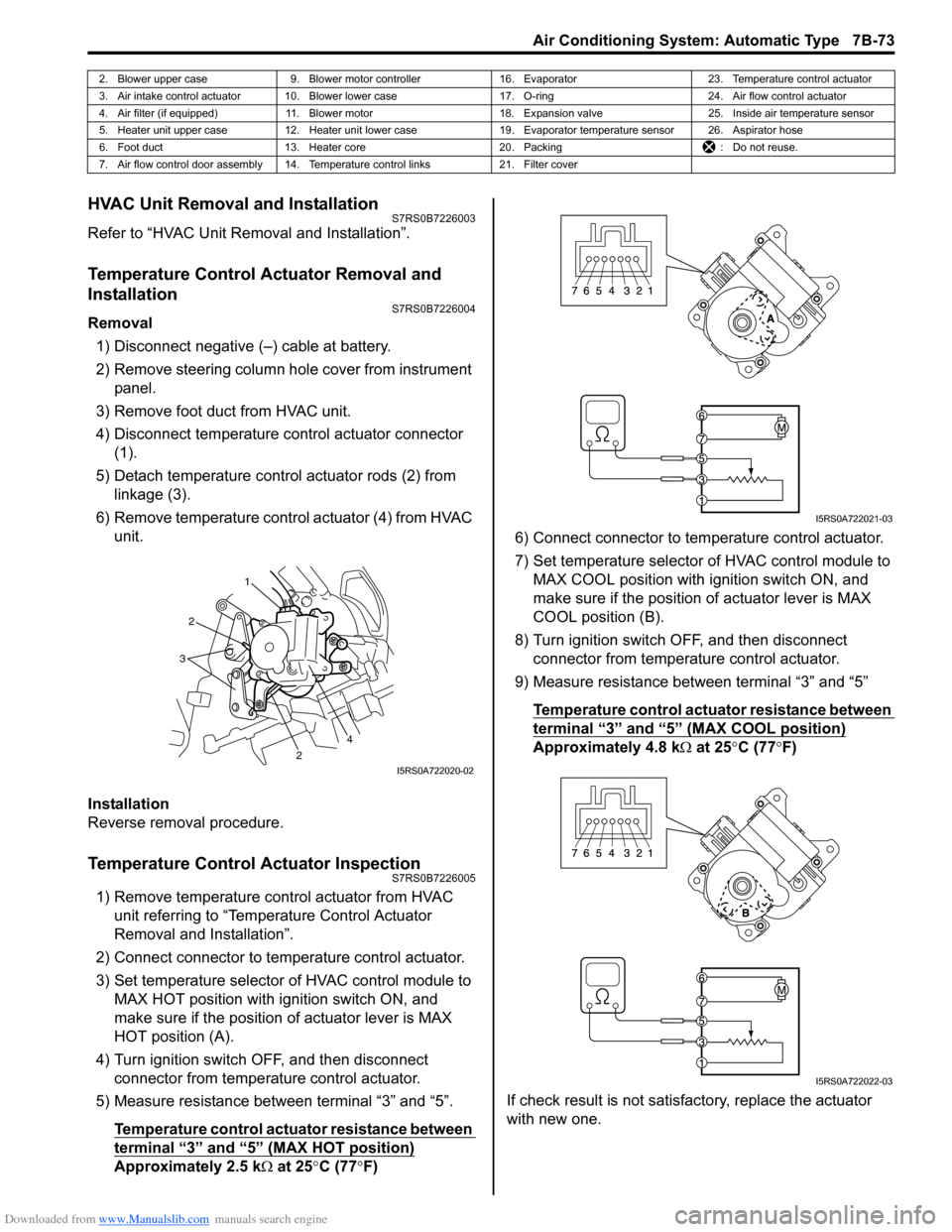
4) Disconnect temperature control actuator connector (1).
5) Detach temperature control actuator rods (2) from linkage (3).
6) Remove temperature control actuator (4) from HVAC unit.
Installation
Reverse removal procedure.
Temperature Control Actuator InspectionS7RS0B7226005
1) Remove temperature control actuator from HVAC unit referring to “Temperature Control Actuator
Removal and Installation”.
2) Connect connector to temperature control actuator.
3) Set temperature selector of HVAC control module to MAX HOT position with ignition switch ON, and
make sure if the position of actuator lever is MAX
HOT position (A).
4) Turn ignition switch OFF, and then disconnect connector from temperature control actuator.
5) Measure resistance between terminal “3” and “5”.
Temperature control actuator resistance between
terminal “3” and “5” (MAX HOT position)
Approximately 2.5 k Ω at 25 °C (77 °F) 6) Connect connector to tem
perature control actuator.
7) Set temperature selector of HVAC control module to MAX COOL position with ignition switch ON, and
make sure if the position of actuator lever is MAX
COOL position (B).
8) Turn ignition switch OFF, and then disconnect connector from temperature control actuator.
9) Measure resistance between terminal “3” and “5”
Temperature control actuator resistance between
terminal “3” and “5” (MAX COOL position)
Approximately 4.8 k Ω at 25 °C (77 °F)
If check result is not satisfactory, replace the actuator
with new one.
2. Blower upper case 9. Blower motor controller 16. Evaporator 23. Temperature control actuator
3. Air intake control actuator 10. Blower lower case 17. O-ring24. Air flow control actuator
4. Air filter (if equipped) 11. Blower motor 18. Expansion valve25. Inside air temperature sensor
5. Heater unit upper case 12. Heater unit lower case 19. Evaporator temperature sensor 26. Aspirator hose
6. Foot duct 13. Heater core 20. Packing : Do not reuse.
7. Air flow control door assembly 14. Temperature control links 21. Filter cover
1
2
2
3
4
I5RS0A722020-02
I5RS0A722021-03
I5RS0A722022-03
Page 1025 of 1496
Downloaded from www.Manualslib.com manuals search engine Air Conditioning System: Automatic Type 7B-77
HVAC Control Module Removal and InstallationS7RS0B7226013
Removal1) Disconnect negative (–) cable at battery.
2) Disable air bag system referring to “Disabling Air Bag System in Section 8B”.
3) Remove passenger air bag module from instrument panel referring to “Passenger Air Bag (Inflator)
Module Removal and Installation in Section 8B”.
4) Remove radio assembly from instrument panel referring to “Rear Speaker Removal and Installation
in Section 9C”.
5) Remove two connectors fr om HVAC control module.
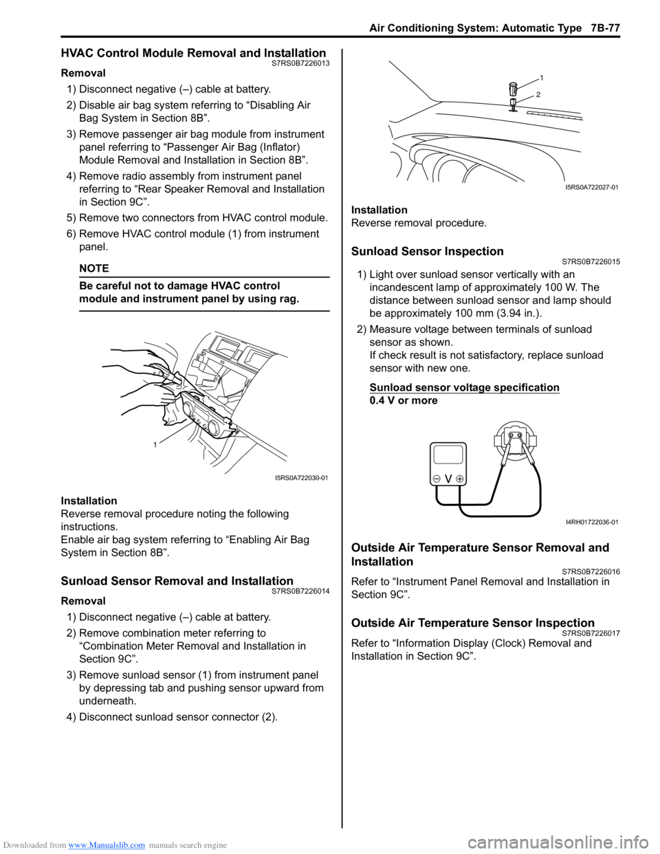
6) Remove HVAC control modu le (1) from instrument
panel.
NOTE
Be careful not to damage HVAC control
module and instrument panel by using rag.
Installation
Reverse removal procedure noting the following
instructions.
Enable air bag system referring to “Enabling Air Bag
System in Section 8B”.
Sunload Sensor Removal and InstallationS7RS0B7226014
Removal
1) Disconnect negative (–) cable at battery.
2) Remove combination meter referring to “Combination Meter Removal and Installation in
Section 9C”.
3) Remove sunload sensor (1) from instrument panel by depressing tab and pushing sensor upward from
underneath.
4) Disconnect sunload sensor connector (2). Installation
Reverse removal procedure.
Sunload Sensor InspectionS7RS0B7226015
1) Light over sunload sensor vertically with an
incandescent lamp of approximately 100 W. The
distance between sunload sensor and lamp should
be approximately 100 mm (3.94 in.).
2) Measure voltage between terminals of sunload sensor as shown.
If check result is not satisfactory, replace sunload
sensor with new one.
Sunload sensor voltage specification
0.4 V or more
Outside Air Temperature Sensor Removal and
Installation
S7RS0B7226016
Refer to “Instrument Panel Re moval and Installation in
Section 9C”.
Outside Air Temperature Sensor InspectionS7RS0B7226017
Refer to “Information Display (Clock) Removal and
Installation in Section 9C”.
1
I5RS0A722030-01
1
2
I5RS0A722027-01
I4RH01722036-01
Page 1026 of 1496
Downloaded from www.Manualslib.com manuals search engine 7B-78 Air Conditioning System: Automatic Type
Inside Air Temperature Sensor Removal and
Installation
S7RS0B7226018
Removal1) Disconnect negative (–) cable at battery.
2) Remove steering column hole cover.
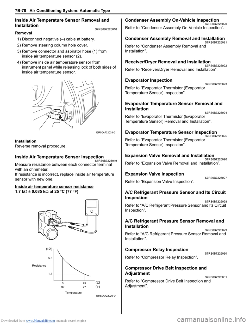
3) Remove connector and aspirator hose (1) from inside air temperature sensor (2).
4) Remove inside air temperature sensor from instrument panel while releas ing lock of both sides of
inside air temperature sensor.
Installation
Reverse removal procedure.
Inside Air Temperature Sensor InspectionS7RS0B7226019
Measure resistance between each connector terminal
with an ohmmeter.
If resistance is incorrect, replace inside air temperature
sensor with new one.
Inside air temperature sensor resistance
1.7 k Ω ± 0.085 k Ω at 25 °C (77 ° F)
Condenser Assembly On-Vehicle InspectionS7RS0B7226020
Refer to “Condenser Assembly On-Vehicle Inspection”.
Condenser Assembly Removal and InstallationS7RS0B7226021
Refer to “Condenser Assembly Removal and
Installation”.
Receiver/Dryer Removal and InstallationS7RS0B7226022
Refer to “Receiver/Dryer Removal and Installation”.
Evaporator InspectionS7RS0B7226023
Refer to “Evaporator Thermistor (Evaporator
Temperature Sensor) Inspection”.
Evaporator Temperature Sensor Removal and
Installation
S7RS0B7226024
Refer to “Evaporator Thermistor (Evaporator
Temperature Sensor) Removal and Installation”.
Evaporator Temperature Sensor InspectionS7RS0B7226025
Refer to “Evaporator Thermistor (Evaporator
Temperature Sensor) Inspection”.
Expansion Valve Removal and InstallationS7RS0B7226026
Refer to “Expansion Valve Removal and Installation”.
Expansion Valve InspectionS7RS0B7226027
Refer to “Expansion Valve Inspection”.
A/C Refrigerant Pressure Sensor and Its Circuit
Inspection
S7RS0B7226028
Refer to “A/C Refrigerant Pressure Sensor and Its Circuit
Inspection”.
A/C Refrigerant Pressure Sensor Removal and
Installation
S7RS0B7226029
Refer to “A/C Refrigerant Pressure Sensor Removal and
Installation”.
Compressor Relay InspectionS7RS0B7226030
Refer to “Compressor Relay Inspection”.
Compressor Drive Belt Inspection and
Adjustment
S7RS0B7226031
Refer to “Compressor Drive Belt Inspection and
Adjustment”.
12I5RS0A722028-01
Temperature
Resistance
1.7
0
32 25
77
F
5.5
I5RS0A722029-01
Page 1027 of 1496
Downloaded from www.Manualslib.com manuals search engine Air Conditioning System: Automatic Type 7B-79
Compressor Drive Belt Removal and
Installation
S7RS0B7226032
Refer to “Compressor Drive Belt Removal and
Installation”.
Compressor Assembly Removal and
Installation
S7RS0B7226033
Refer to “Compressor Assembly Removal and
Installation”.
Compressor Assembly ComponentsS7RS0B7226034
Refer to “Compressor Assembly Components”.
Magnet Clutch Removal and InstallationS7RS0B7226035
Refer to “Magnet Clutch Removal and Installation”.
Magnet Clutch InspectionS7RS0B7226036
Refer to “Magnet Clutch Inspection”.
Relief Valve InspectionS7RS0B7226039
Refer to “Relief Valve Inspection”.
Special Tools and Equipment
Special ToolS7RS0B7228001
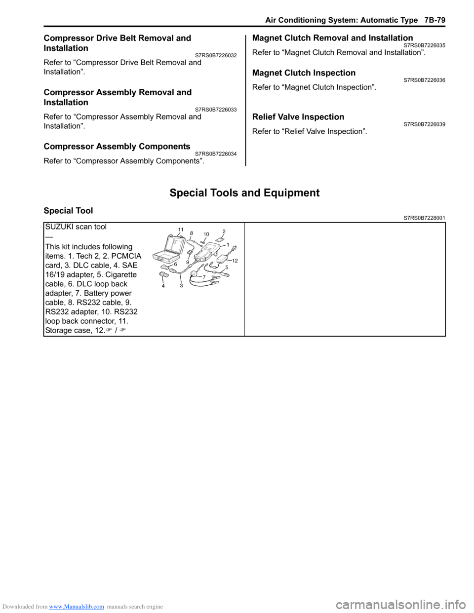
SUZUKI scan tool
—
This kit includes following
items. 1. Tech 2, 2. PCMCIA
card, 3. DLC cable, 4. SAE
16/19 adapter, 5. Cigarette
cable, 6. DLC loop back
adapter, 7. Battery power
cable, 8. RS232 cable, 9.
RS232 adapter, 10. RS232
loop back connector, 11.
Storage case, 12.�) / �)
Page 1035 of 1496
Downloaded from www.Manualslib.com manuals search engine Seat Belts: 8A-4
Front Seat Belt Removal and InstallationS7RS0B8106002
WARNING!
• Never attempt to disassemble or repair the seat belt pretensioner (retractor
assembly). If any abnormality is found, be
sure to replace it with new one as an
assembly.
• Be sure to read “Precautions on Service and Diagnosis of Seat Belt” before starting
to work and observe every precaution
during work. Ne glecting them may result in
personal injury or una ctivation of the seat
belt pretensioner when necessary.
Removal
1) Disconnect negative (–) cable at battery.
2) Disable air bag system. Refer to “Disabling Air Bag System in Section 8B”.
3) Remove center pillar lower trim.
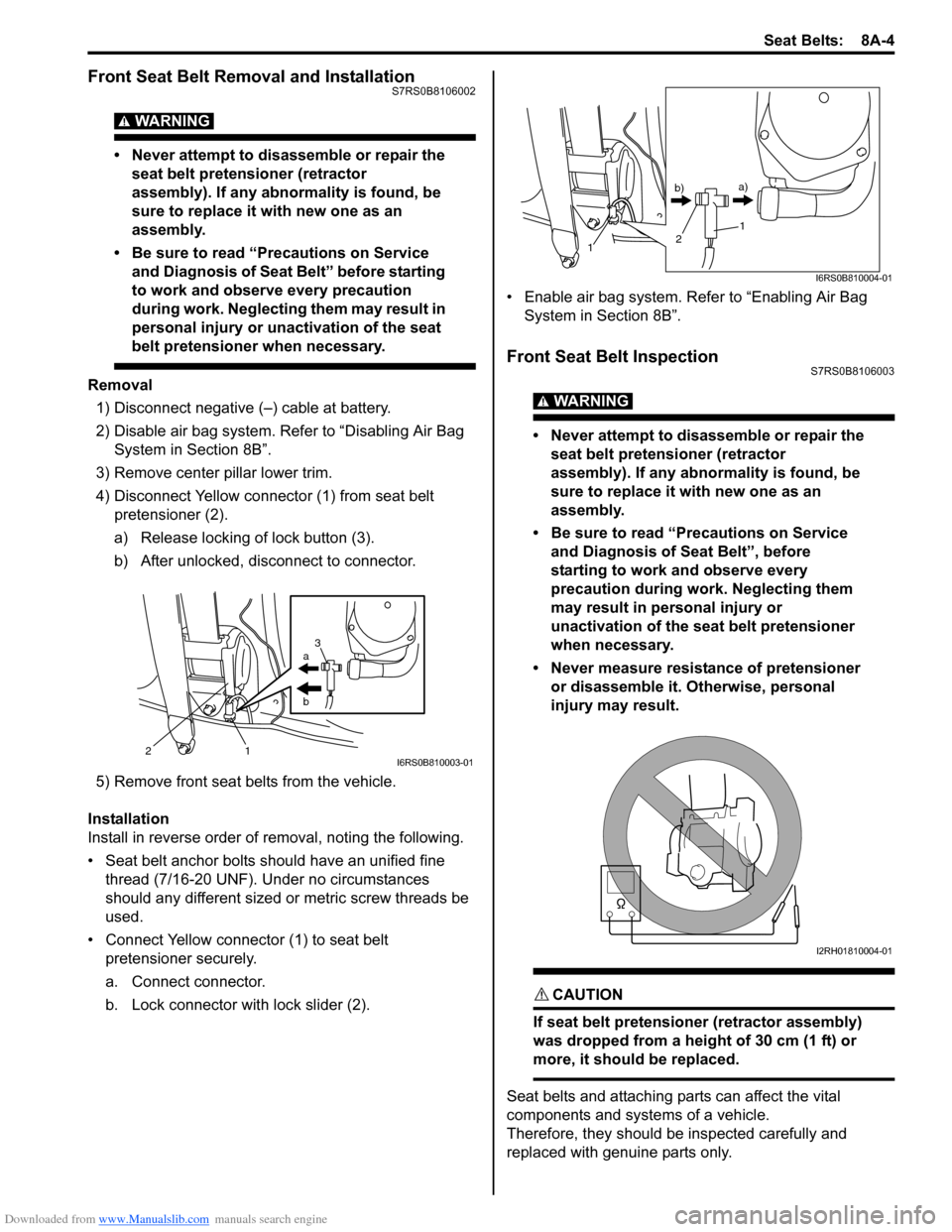
4) Disconnect Yellow connector (1) from seat belt pretensioner (2).
a) Release locking of lock button (3).
b) After unlocked, disconnect to connector.
5) Remove front seat belts from the vehicle.
Installation
Install in reverse order of removal, noting the following.
• Seat belt anchor bolts should have an unified fine thread (7/16-20 UNF). Under no circumstances
should any different sized or metric screw threads be
used.
• Connect Yellow connector (1) to seat belt pretensioner securely.
a. Connect connector.
b. Lock connector with lock slider (2). • Enable air bag system. Refer to “Enabling Air Bag
System in Section 8B”.
Front Seat Belt InspectionS7RS0B8106003
WARNING!
• Never attempt to disassemble or repair the seat belt pretensioner (retractor
assembly). If any abnormality is found, be
sure to replace it with new one as an
assembly.
• Be sure to read “Precautions on Service and Diagnosis of Seat Belt”, before
starting to work and observe every
precaution during work. Neglecting them
may result in personal injury or
unactivation of the seat belt pretensioner
when necessary.
• Never measure resistance of pretensioner or disassemble it. Otherwise, personal
injury may result.
CAUTION!
If seat belt pretensioner (retractor assembly)
was dropped from a height of 30 cm (1 ft) or
more, it should be replaced.
Seat belts and attaching parts can affect the vital
components and systems of a vehicle.
Therefore, they should be inspected carefully and
replaced with genuine parts only.
a
b
21 3I6RS0B810003-01
1
1
2
b)
a)
I6RS0B810004-01
I2RH01810004-01