Signal SUZUKI SWIFT 2007 2.G Service Workshop Manual
[x] Cancel search | Manufacturer: SUZUKI, Model Year: 2007, Model line: SWIFT, Model: SUZUKI SWIFT 2007 2.GPages: 1496, PDF Size: 34.44 MB
Page 579 of 1496
Downloaded from www.Manualslib.com manuals search engine Electronic Stability Program: 4F-5
Yaw rate / G sensor
The yaw rate / G sensor consists of the yaw rate (angular velocity in the vehicle turning direction) sensor and right-left
G (acceleration in right-left direction) sensor and is mounted to the P/S controller B/K at the lower part of the center
console. It detects the angular velocity in the vehicle turn ing direction and movement in the right-left direction, and
then it sends that information to ESP ® control module.
Wheel speed sensor
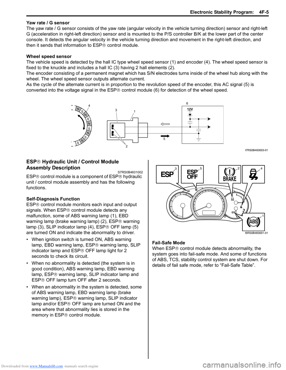
The vehicle speed is detected by the hall IC type wheel speed sensor (1) and encoder (4). The wheel speed sensor is
fixed to the knuckle and includes a hall IC (3) having 2 hall elements (2).
The encoder consisting of a permanent ma gnet which has S/N electrodes turns inside of the wheel hub along with the
wheel. The wheel speed sensor outputs alternate current.
As the cycle of the alternate current is in proportion to the revolution speed of the encoder, this AC signal (5) is
converted into the voltage signal in the ESP ® control module (6) for detection of the wheel speed.
ESP ® Hydraulic Unit / Control Module
Assembly Description
S7RS0B4601002
ESP ® control module is a component of ESP ® hydraulic
unit / control module assembly and has the following
functions.
Self-Diagnosis Function
ESP ® control module monitors each input and output
signals. When ESP ® control module detects any
malfunction, some of ABS warning lamp (1), EBD
warning lamp (brake warning lamp) (2), ESP ® warning
lamp (3), SLIP indicator lamp (4), ESP ® OFF lamp (5)
are turned ON and indicate the abnormality to driver.
• When ignition switch is turned ON, ABS warning lamp, EBD warning lamp, ESP ® warning lamp, SLIP
indicator lamp and ESP ® OFF lamp light for 2
seconds to check its circuit.
• When no abnormality is detected (the system is in good condition), ABS warning lamp, EBD warning
lamp, ESP ® warning lamp, SLIP indicator lamp and
ESP ® OFF lamp turn OFF after 2 seconds.
• When an abnormality in the system is detected, some of ABS warning lamp, EBD warning lamp (brake
warning lamp), ESP ® warning lamp, SLIP indicator
lamp and/or ESP ® OFF lamp are turned ON and the
area where that abnormality lies is stored in the
memory in ESP ® control module. Fail-Safe Mode
When ESP
® control module detects abnormality, the
system goes into fail-safe mode. And some of functions
of ABS, TCS, stability control system are shut down. For
details of fail safe mode, re fer to “Fail-Safe Table”.
S
N
S
N
S
N
N
S
N
S
12V
2
3
1
5
4
6I7RS0B460003-01
3245
1
I6RS0B460001-01
Page 580 of 1496
Downloaded from www.Manualslib.com manuals search engine 4F-6 Electronic Stability Program:
Warning Lamp, Indicator Lamp DescriptionS7RS0B4601003
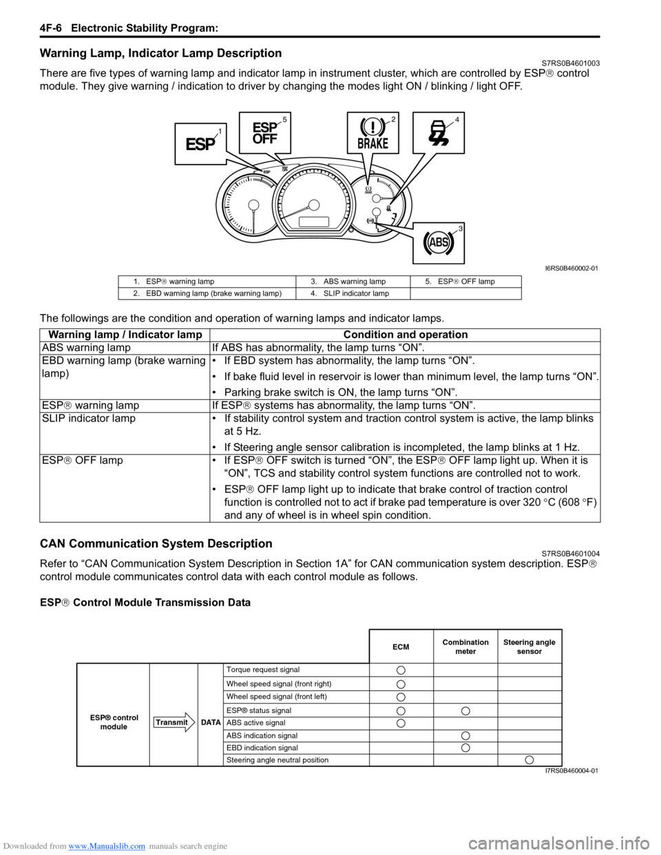
There are five types of warning lamp and indicator lamp in instrument cluster, which are controlled by ESP ® control
module. They give warning / indication to driver by changing the modes light ON / blinking / light OFF.
The followings are the condition and operation of warning lamps and indicator lamps.
CAN Communication System DescriptionS7RS0B4601004
Refer to “CAN Communication System Description in Section 1A” for CAN communication system description. ESP ®
control module communicates control data with each control module as follows.
ESP ® Control Module Transmission Data
1
245
3
I6RS0B460002-01
1. ESP ® warning lamp 3. ABS warning lamp 5. ESP ® OFF lamp
2. EBD warning lamp (brake warning lamp) 4. SLIP indicator lamp
Warning lamp / Indicator lamp Condition and operation
ABS warning lamp If ABS has abnor mality, the lamp turns “ON”.
EBD warning lamp (brake warning
lamp) • If EBD system has abnormality, the lamp turns “ON”.
• If bake fluid level in reservoir is lower
than minimum level, the lamp turns “ON”.
• Parking brake switch is ON, the lamp turns “ON”.
ESP ® warning lamp If ESP ® systems has abnormality, the lamp turns “ON”.
SLIP indicator lamp • If stability cont rol system and traction control system is active, the lamp blinks
at 5 Hz.
• If Steering angle sensor calibration is incompleted, the lamp blinks at 1 Hz.
ESP ® OFF lamp • If ESP ® OFF switch is turned “ON”, the ESP ® OFF lamp light up. When it is
“ON”, TCS and stability control system functions are controlled not to work.
• ESP® OFF lamp light up to indicate th at brake control of traction control
function is controlled not to act if brake pad temperature is over 320 °C (608 °F)
and any of wheel is in wheel spin condition.
Combination
meter
Transmit DATA
ESP® control
moduleECMSteering angle sensor
Torque request signal
Wheel speed signal (front right)
Wheel speed signal (front left)
ESP® status signal
ABS active signal
ABS indication signal
EBD indication signal
Steering angle neutral position
I7RS0B460004-01
Page 581 of 1496
Downloaded from www.Manualslib.com manuals search engine Electronic Stability Program: 4F-7
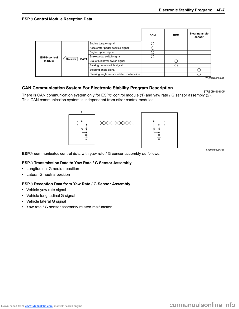
ESP® Control Module Reception Data
CAN Communication System For Electronic Stability Program DescriptionS7RS0B4601005
There is CAN communication system only for ESP ® control module (1) and yaw rate / G sensor assembly (2).
This CAN communication system is independent from other control modules.
ESP ® communicates control data with yaw rate / G sensor assembly as follows.
ESP ® Transmission Data to Yaw Rate / G Sensor Assembly
• Longitudinal G neutral position
• Lateral G neutral position
ESP ® Reception Data from Yaw Rate / G Sensor Assembly
• Vehicle yaw rate signal
• Vehicle longitudinal G signal
• Vehicle lateral G signal
• Yaw rate / G sensor assembly related malfunction
BCM
Receive DATA
ESP® control
moduleECMSteering angle sensor
Engine torque signal
Accelerator pedal position signal
Engine speed signal
Brake pedal switch signal
Brake fluid level switch signal
Parking brake switch signal
Steering angle signal
Steering angle sensor related malfunction
I7RS0B460005-01
2 1
I6JB01460006-01
Page 589 of 1496
Downloaded from www.Manualslib.com manuals search engine Electronic Stability Program: 4F-15
EBD Warning Lamp (Brake Warning Lamp)
Check
S7RS0B4604047
NOTE
Perform this check on a level place.
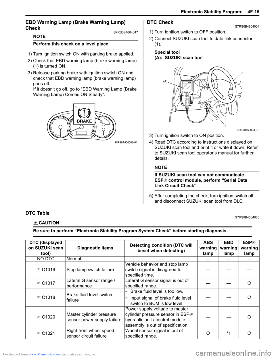
1) Turn ignition switch ON with parking brake applied.
2) Check that EBD warning lamp (brake warning lamp)
(1) is turned ON.
3) Release parking brake with ignition switch ON and check that EBD warning lamp (brake warning lamp)
goes off.
If it doesn't go off, go to “EBD Warning Lamp (Brake
Warning Lamp) Comes ON Steady”.
DTC CheckS7RS0B4604004
1) Turn ignition switch to OFF position.
2) Connect SUZUKI scan tool to data link connector (1).
Special tool
(A): SUZUKI scan tool
3) Turn ignition switch to ON position.
4) Read DTC according to instructions displayed on
SUZUKI scan tool and print it or write it down. Refer
to SUZUKI scan tool operator’s manual for further
details.
NOTE
If SUZUKI scan tool can not communicate
ESP® control module, perform “Serial Data
Link Circuit Check”.
5) After completing the check, turn ignition switch off and disconnect SUZUKI scan tool from DLC.
DTC TableS7RS0B4604005
CAUTION!
Be sure to perform “Electronic Stability Program System Check” before starting diagnosis.
BRAKE
1
I4RS0A450008-01
(A)
1
I4RS0B450003-01
DTC (displayed
on SUZUKI scan tool) Diagnostic Items
Detecting condition (DTC will
beset when detecting) ABS
warning lamp EBD
warning lamp ESP
®
warning lamp
NO DTC Normal — — — —
�) C1016 Stop lamp switch failure Vehicle behavior and stop lamp
switch signal is disagreed for
specified time.———
�) C1017 Lateral G sensor range /
performance Lateral G sensor signal is out of
specified range.
——
�{
�) C1018 Brake fluid level switch
failure • Brake fluid level is too low.
• Input signal of brake fluid level
switch to BCM is low level. ——
�{
�) C1020 Master cylinder pressure
sensor power supply failure Power supply volt
age to master
cylinder pressure sensor in ESP ®
hydraulic unit / control module
assembly is out of specification. ——
�{
�) C1021 Right-front wheel speed
sensor circuit failure Wheel sensor signal is out of
specified range.
�{
*1 �{
Page 590 of 1496
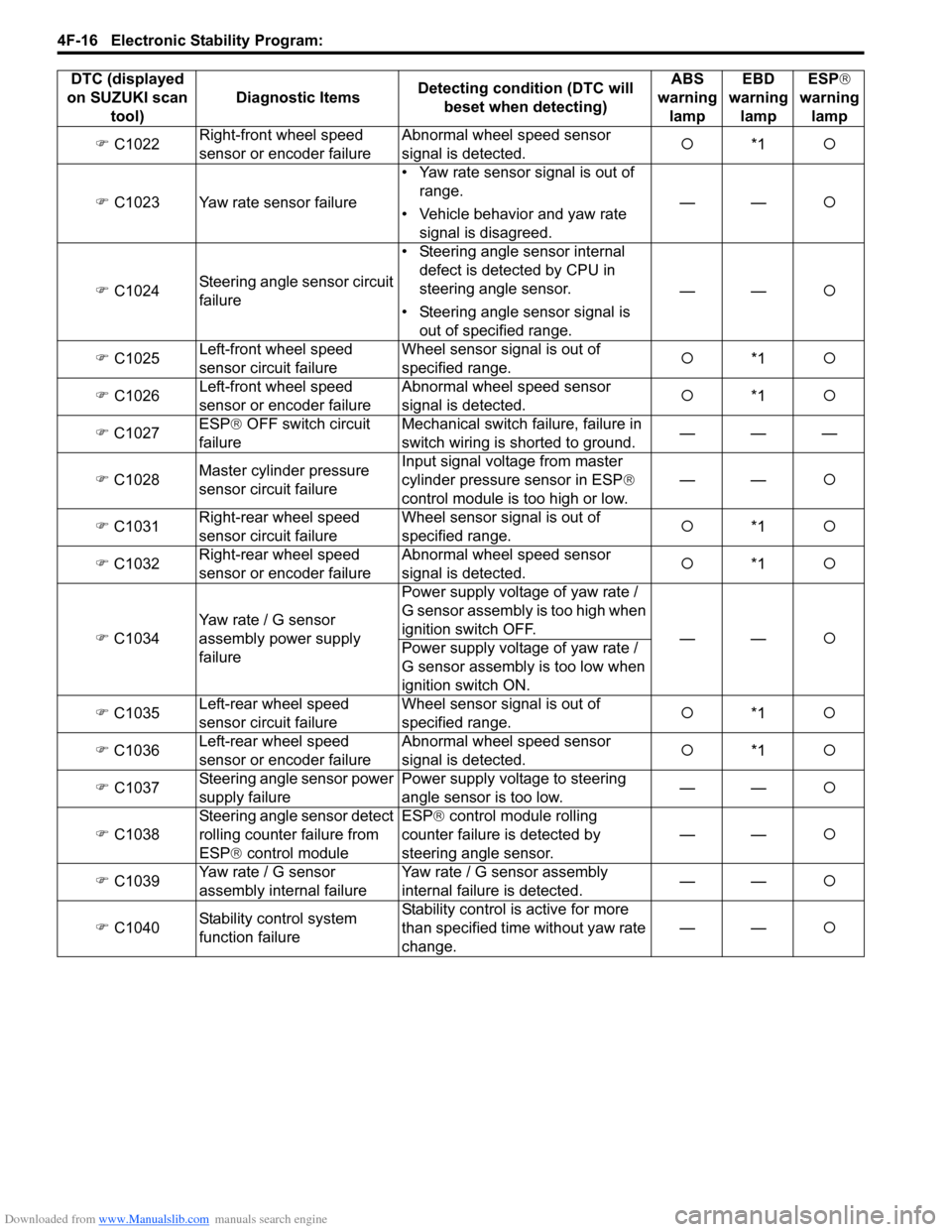
Downloaded from www.Manualslib.com manuals search engine 4F-16 Electronic Stability Program:
�) C1022 Right-front wheel speed
sensor or encoder failure Abnormal wheel speed sensor
signal is detected.
�{
*1 �{
�) C1023 Yaw rate sensor failure • Yaw rate sensor signal is out of
range.
• Vehicle behavior and yaw rate signal is disagreed. ——
�{
�) C1024 Steering angle sensor circuit
failure • Steering angle sensor internal
defect is detected by CPU in
steering angle sensor.
• Steering angle sensor signal is out of specified range. ——
�{
�) C1025 Left-front wheel speed
sensor circuit failure Wheel sensor signal is out of
specified range.
�{
*1 �{
�) C1026 Left-front wheel speed
sensor or encoder failure Abnormal wheel speed sensor
signal is detected.
�{
*1 �{
�) C1027 ESP
® OFF switch circuit
failure Mechanical switch failure, failure in
switch wiring is shorted to ground.
———
�) C1028 Master cylinder pressure
sensor circuit failure Input signal voltage from master
cylinder pressure sensor in ESP
®
control module is too high or low. ——
�{
�) C1031 Right-rear wheel speed
sensor circuit failure Wheel sensor signal is out of
specified range.
�{
*1 �{
�) C1032 Right-rear wheel speed
sensor or encoder failure Abnormal wheel speed sensor
signal is detected.
�{
*1 �{
�) C1034 Yaw rate / G sensor
assembly power supply
failure Power supply voltage of yaw rate /
G sensor assembly is too high when
ignition switch OFF.
——�{
Power supply voltage of yaw rate /
G sensor assembly is too low when
ignition switch ON.
�) C1035 Left-rear wheel speed
sensor circuit failure Wheel sensor signal is out of
specified range.
�{
*1 �{
�) C1036 Lef
t-rear wheel speed
sensor or encoder failure Abnormal wheel speed sensor
signal is detected.
�{
*1 �{
�) C1037 Steering angle sensor power
supply failure Power supply voltage to steering
angle sensor is too low.
——
�{
�) C1038 Steering angle sensor detect
rolling counter failure from
ESP
® control module ESP
® control module rolling
counter failure is detected by
steering angle sensor. ——
�{
�) C1039 Yaw rate / G sensor
assembly internal failure Yaw rate / G sensor assembly
internal failure is detected.
——
�{
�) C1040 Stability control system
function failure Stability control is active for more
than specified time
without yaw rate
change. ——
�{
DTC (displayed
on SUZUKI scan tool) Diagnostic Items
Detecting condition (DTC will
beset when detecting) ABS
warning lamp EBD
warning lamp ESP
®
warning lamp
Page 591 of 1496
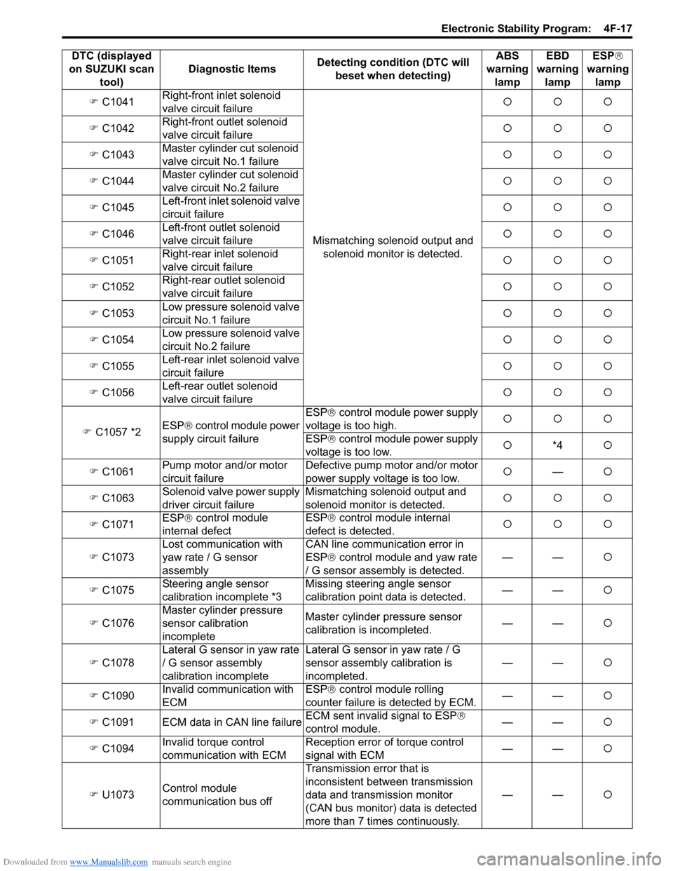
Downloaded from www.Manualslib.com manuals search engine Electronic Stability Program: 4F-17
�) C1041 Right-front inlet solenoid
valve circuit failure
Mismatching solenoid output and solenoid monitor is detected. �{�{�{
�) C1042 Right-front outlet solenoid
valve circuit failure �{�{�{
�) C1043 Master cylinder cut solenoid
valve circuit No.1 failure �{�{�{
�) C1044 Master cylinder cut solenoid
valve circuit No.2 failure �{�{�{
�) C1045 Left-front inlet solenoid valve
circuit failure �{�{�{
�) C1046 Left-front outlet solenoid
valve circuit failure �{�{�{
�) C1051 Right-rear inlet solenoid
valve circuit failure �{�{�{
�) C1052 Right-rear outlet solenoid
valve circuit failure �{�{�{
�) C1053 Low pressure solenoid valve
circuit No.1 failure �{�{�{
�) C1054 Low pressure solenoid valve
circuit No.2 failure �{�{�{
�) C1055 Left-rear inlet solenoid valve
circuit failure �{�{�{
�) C1056 Left-rear outlet solenoid
valve circuit failure �{�{�{
�) C1057 *2 ESP
® control module power
supply circuit failure ESP®
control module power supply
voltage is too high. �{�{�{
ESP® control module power supply
voltage is too low. �{
*4 �{
�) C1061 Pump motor and/or motor
circuit failure Defective pump motor and/or motor
power supply voltage is too low.
�{
— �{
�) C1063 Solenoid valve
power supply
driver circuit failure Mismatching solenoid output and
solenoid monitor is detected.
�{�{�{
�) C1071 ESP
® con
trol module
internal defect ESP®
control module internal
defect is detected. �{�{�{
�) C1073 Lost communication with
yaw rate / G sensor
assembly CAN line communication error in
ESP®
control module and yaw rate
/ G sensor assembly is detected. ——
�{
�) C1075 Steering angle sensor
calibration incomplete *3 Missing steering angle sensor
calibration point data is detected.
——
�{
�) C1076 Master cylinder pressure
sensor calibration
incomplete Master cylinder pressure sensor
calibration is incompleted.
——
�{
�) C1078 Lateral G sensor in yaw rate
/ G sensor assembly
calibration incomplete Lateral G sensor in yaw rate / G
sensor assembly calibration is
incompleted.
——
�{
�) C1090 Invalid communication with
ECM ESP®
control module rolling
counter failure is detected by ECM. ——
�{
�) C1091 ECM data in CAN line failure ECM sent invalid signal to ESP
®
control module. ——
�{
�) C1094 Invalid torque control
communication with ECM Reception error of torque control
signal with ECM
——
�{
�) U1073 Control module
communication bus off Transmission error that is
inconsistent between transmission
data and transmission monitor
(CAN bus monitor) data is detected
more than 7 times continuously.
——
�{
DTC (displayed
on SUZUKI scan tool) Diagnostic Items
Detecting condition (DTC will
beset when detecting) ABS
warning lamp EBD
warning lamp ESP
®
warning lamp
Page 594 of 1496
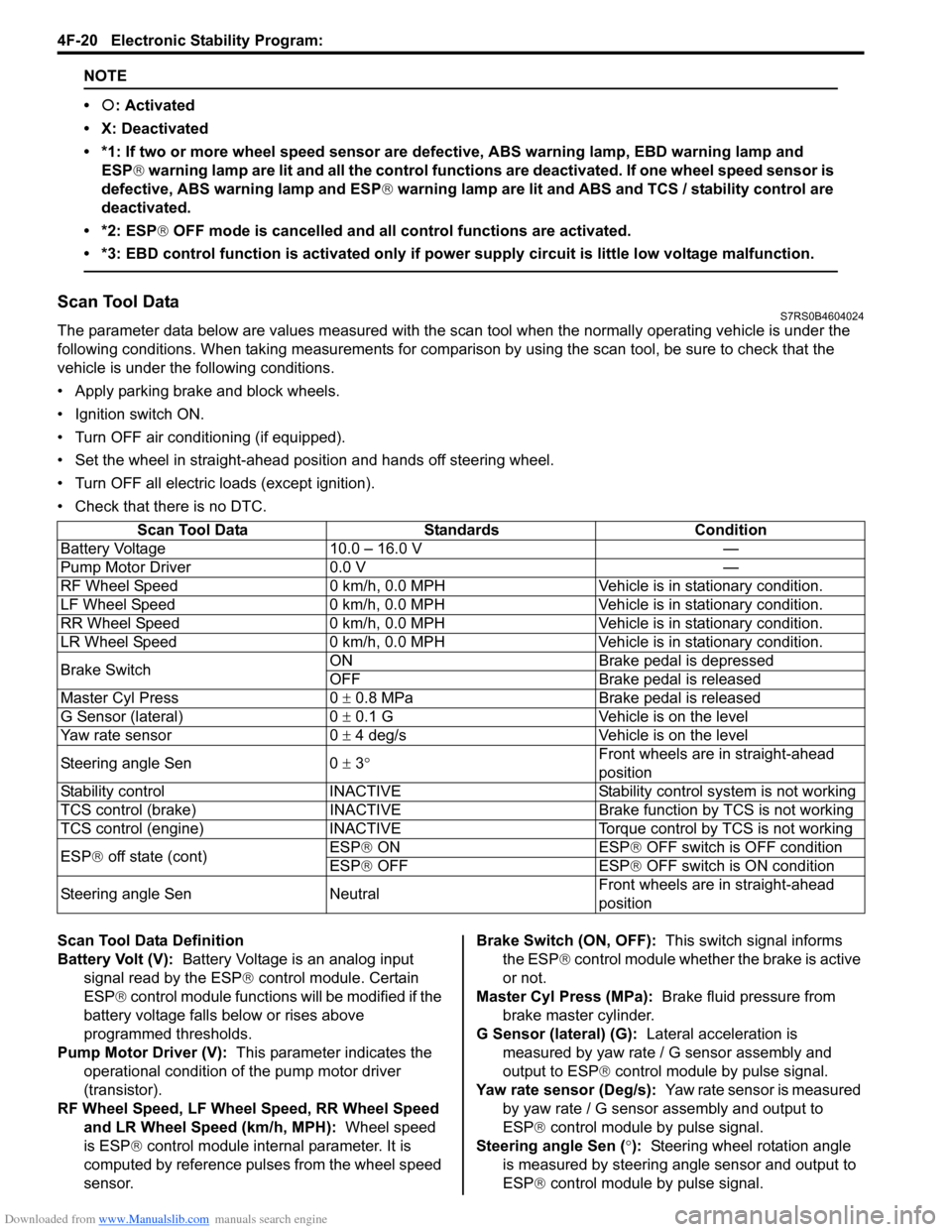
Downloaded from www.Manualslib.com manuals search engine 4F-20 Electronic Stability Program:
NOTE
•�{: Activated
• X: Deactivated
• *1: If two or more wheel speed sensor are defective, ABS warning lamp, EBD warning lamp and ESP ® warning lamp are lit and all the control functions are deactivated. If one wheel speed sensor is
defective, ABS warning lamp and ESP ® warning lamp are lit and ABS and TCS / stability control are
deactivated.
• *2: ESP ® OFF mode is cancelled and all control functions are activated.
• *3: EBD control function is activated only if po wer supply circuit is little low voltage malfunction.
Scan Tool DataS7RS0B4604024
The parameter data below are values measured with the scan tool when the normally operating vehicle is under the
following conditions. When taking measurements for comparis on by using the scan tool, be sure to check that the
vehicle is under the following conditions.
• Apply parking brake and block wheels.
• Ignition switch ON.
• Turn OFF air conditioning (if equipped).
• Set the wheel in straight-ahead position and hands off steering wheel.
• Turn OFF all electric loads (except ignition).
• Check that there is no DTC.
Scan Tool Data Definition
Battery Volt (V): Battery Voltage is an analog input
signal read by the ESP ® control module. Certain
ESP ® control module functions will be modified if the
battery voltage falls below or rises above
programmed thresholds.
Pump Motor Driver (V): This parameter indicates the
operational condition of the pump motor driver
(transistor).
RF Wheel Speed, LF Wheel Speed, RR Wheel Speed and LR Wheel Speed (km/h, MPH): Wheel speed
is ESP ® control module internal parameter. It is
computed by reference puls es from the wheel speed
sensor. Brake Switch (ON, OFF):
This switch signal informs
the ESP ® control module whether the brake is active
or not.
Master Cyl Press (MPa): Brake fluid pressure from
brake master cylinder.
G Sensor (lateral) (G): Lateral acceleration is
measured by yaw rate / G sensor assembly and
output to ESP ® control module by pulse signal.
Yaw rate sensor (Deg/s): Yaw rate sensor is measured
by yaw rate / G sensor assembly and output to
ESP® control module by pulse signal.
Steering angle Sen ( °): Steering wheel rotation angle
is measured by steering angle sensor and output to
ESP® control module by pulse signal.
Scan Tool Data Standards Condition
Battery Voltage 10.0 – 16.0 V —
Pump Motor Driver 0.0 V —
RF Wheel Speed 0 km/h, 0.0 MPH Veh icle is in stationary condition.
LF Wheel Speed 0 km/h, 0.0 MPH Veh icle is in stationary condition.
RR Wheel Speed 0 km/h, 0.0 MPH Vehic le is in stationary condition.
LR Wheel Speed 0 km/h, 0.0 MPH Veh icle is in stationary condition.
Brake Switch ON Brake pedal is depressed
OFF Brake pedal is released
Master Cyl Press 0 ± 0.8 MPa Brake pedal is released
G Sensor (lateral) 0 ± 0.1 G Vehicle is on the level
Yaw rate sensor 0 ± 4 deg/s Vehicle is on the level
Steering angle Sen 0 ± 3 ° Front wheels are in straight-ahead
position
Stability control INACTIVE Stability control system is not working
TCS control (brake) INACTIVE Brake function by TCS is not working
TCS control (engine) INACTIVE Torque control by TCS is not working
ESP ® off state (cont) ESP®
ON ESP
® OF
F switch is OFF condition
ESP® OFF ESP ® OFF switch is ON condition
Steering angle Sen Neutral Front wheels are in straight-ahead
position
Page 603 of 1496
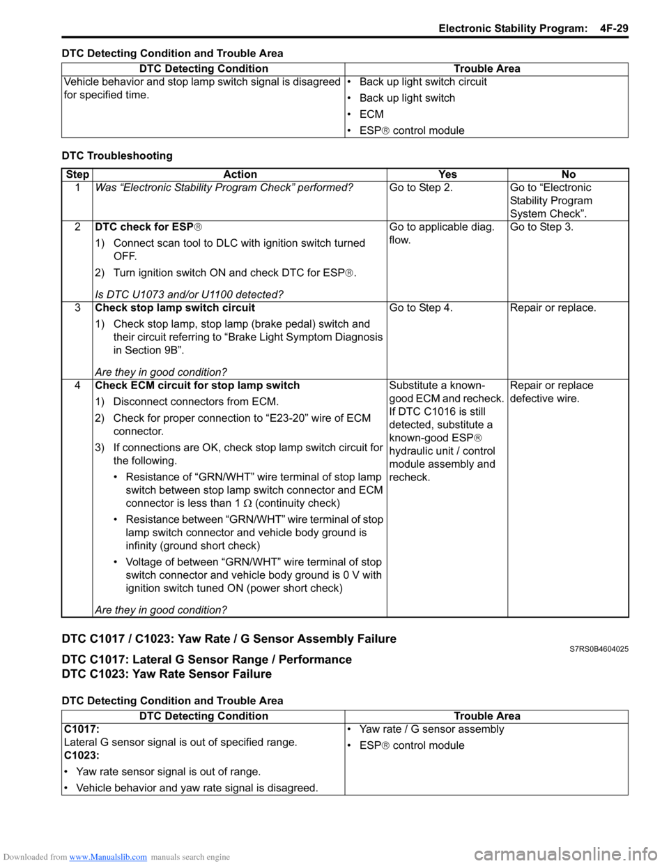
Downloaded from www.Manualslib.com manuals search engine Electronic Stability Program: 4F-29
DTC Detecting Condition and Trouble Area
DTC Troubleshooting
DTC C1017 / C1023: Yaw Rate / G Sensor Assembly FailureS7RS0B4604025
DTC C1017: Lateral G Sensor Range / Performance
DTC C1023: Yaw Rate Sensor Failure
DTC Detecting Condition and Trouble AreaDTC Detecting Condition Trouble Area
Vehicle behavior and stop lamp switch signal is disagreed
for specified time. • Back up light switch circuit
• Back up light switch
•ECM
• ESP
® control module
Step Action YesNo
1 Was “Electronic Stability Pr ogram Check” performed? Go to Step 2.Go to “Electronic
Stability Program
System Check”.
2 DTC check for ESP®
1) Connect scan tool to DLC with ignition switch turned
OFF.
2) Turn ignition switch ON and check DTC for ESP ®.
Is DTC U1073 and/or U1100 detected? Go to applicable diag.
flow.
Go to Step 3.
3 Check stop lamp switch circuit
1) Check stop lamp, stop lamp (brake pedal) switch and
their circuit referring to “Brake Light Symptom Diagnosis
in Section 9B”.
Are they in good condition? Go to Step 4.
Repair or replace.
4 Check ECM circuit for stop lamp switch
1) Disconnect connectors from ECM.
2) Check for proper connection to “E23-20” wire of ECM
connector.
3) If connections are OK, check stop lamp switch circuit for
the following.
• Resistance of “GRN/WHT” wire terminal of stop lamp switch between stop lamp switch connector and ECM
connector is less than 1 Ω (continuity check)
• Resistance between “GRN/WHT” wire terminal of stop lamp switch connector and vehicle body ground is
infinity (ground short check)
• Voltage of between “GRN/WHT” wire terminal of stop switch connector and vehicle body ground is 0 V with
ignition switch tuned ON (power short check)
Are they in good condition? Substitute a known-
good ECM and recheck.
If DTC C1016 is still
detected, substitute a
known-good ESP
®
hydraulic unit / control
module assembly and
recheck. Repair or replace
defective wire.
DTC Detecting Condition
Trouble Area
C1017:
Lateral G sensor signal is out of specified range.
C1023:
• Yaw rate sensor signal is out of range.
• Vehicle behavior and yaw rate signal is disagreed. • Yaw rate / G sensor assembly
• ESP
® control module
Page 604 of 1496
Downloaded from www.Manualslib.com manuals search engine 4F-30 Electronic Stability Program:
DTC Troubleshooting
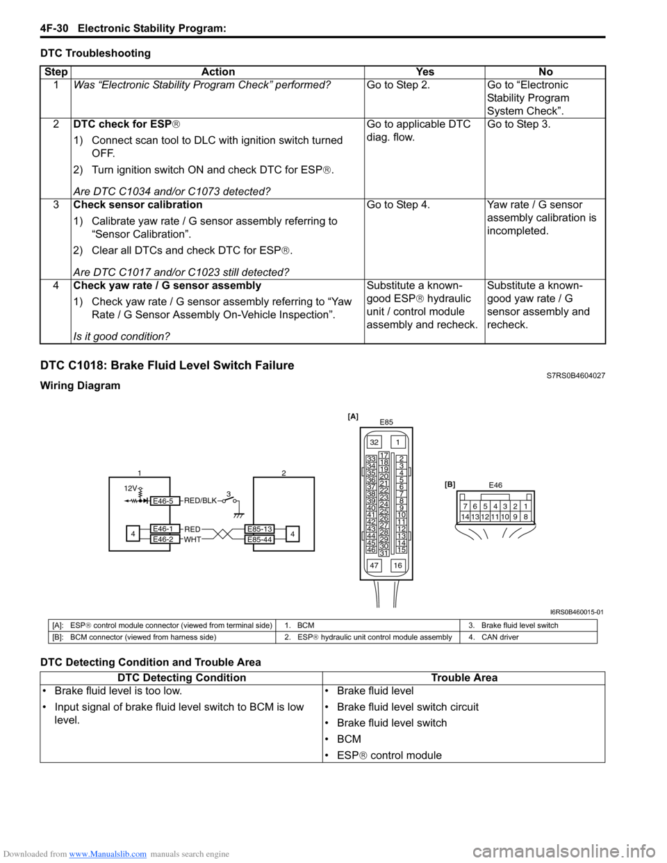
DTC C1018: Brake Fluid Level Switch FailureS7RS0B4604027
Wiring Diagram
DTC Detecting Condition and Trouble AreaStep Action Yes No
1 Was “Electronic Stability Pr ogram Check” performed? Go to Step 2. Go to “Electronic
Stability Program
System Check”.
2 DTC check for ESP®
1) Connect scan tool to DLC with ignition switch turned
OFF.
2) Turn ignition switch ON and check DTC for ESP ®.
Are DTC C1034 and/or C1073 detected? Go to applicable DTC
diag. flow.
Go to Step 3.
3 Check sensor calibration
1) Calibrate yaw rate / G sensor assembly referring to
“Sensor Calibration”.
2) Clear all DTCs and check DTC for ESP ®.
Are DTC C1017 and/or C1023 still detected? Go to Step 4. Yaw rate / G sensor
assembly calibration is
incompleted.
4 Check yaw rate / G sensor assembly
1) Check yaw rate / G sensor assembly referring to “Yaw
Rate / G Sensor Assembly On-Vehicle Inspection”.
Is it good condition? Substitute a known-
good ESP
® hydraulic
unit / control module
assembly and recheck. Substitute a known-
good yaw rate / G
sensor assembly and
recheck.
[A]
E85
161
15
2
3
4
5
6
7
8
9
10
11
12
13
14
17
18
19
20
21
22
23
24
25
26
27
28
29
30
31
3233
34
35
36
37
38
39
40
41
42
43
44
45
46
47 [B]
E46
124
53
67
891011121314
E85-13
E85-44REDWHT4E46-1E46-2
124
12V3E46-5RED/BLK
I6RS0B460015-01
[A]: ESP
® control module connector (viewed from terminal side) 1. BCM 3. Brake fluid level switch
[B]: BCM connector (viewed from harness side) 2. ESP ® hydraulic unit control module assembly 4. CAN driver
DTC Detecting Condition Trouble Area
• Brake fluid level is too low.
• Input signal of brake fluid level switch to BCM is low level. • Brake fluid level
• Brake fluid level switch circuit
• Brake fluid level switch
•BCM
• ESP
® control module
Page 606 of 1496
Downloaded from www.Manualslib.com manuals search engine 4F-32 Electronic Stability Program:
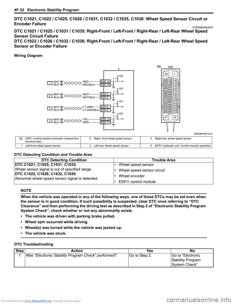
DTC C1021, C1022 / C1025, C1026 / C1031, C1032 / C1035, C1036: Wheel Speed Sensor Circuit or
Encoder Failure
S7RS0B4604051
DTC C1021 / C1025 / C1031 / C1035: Right-Front / Left-Front / Right-Rear / Left-Rear Wheel Speed
Sensor Circuit Failure
DTC C1022 / C1026 / C1032 / C1036: Right-Front / Left-Front / Right-Rear / Left-Rear Wheel Speed
Sensor or Encoder Failure
Wiring Diagram
DTC Detecting Condition and Trouble Area
NOTE
When the vehicle was operated in any of the following ways, one of these DTCs may be set even when
the sensor is in good condition. If such possibility is suspected, clear DTC once referring to “DTC
Clearance” and then performing the driving test as described in Step 2 of “Electronic Stability Program
System Check”, check whether or not any abnormality exists.
• The vehicle was driven with parking brake pulled.
• Wheel spin occurred while driving.
• Wheel(s) was turned while the vehicle was jacked up.
• The vehicle was stuck.
DTC Troubleshooting
[A]E85
161
15
2
3
4
5
6
7
8
9
10
11
12
13
14
17
18
19
20
21
22
23
24
25
26
27
28
29
30
31
3233
34
35
36
37
38
39
40
41
42
43
44
45
46
47
RED/BLKRED E85-15 E85-14
12V
BLKWHT
1
WHT/BLKWHTE85-2 E85-3
12V
BLKWHT
2
BLKWHTLT GRN/BLKLT GRNE85-6 E85-5
12V
3
BLKWHTBRNE85-11 E85-12
12V
4YEL 5
I6RS0B460016-01
[A]: ESP
® control module connector (viewed from
terminal side) 2. Right- front wheel speed sensor 4. Right-rear wheel speed sensor
1. Left-front wheel speed sensor 3. Left-rear wheel speed sensor 5. ESP ® hydraulic unit / control module assembly
DTC Detecting Condition Trouble Area
DTC C1021, C1025, C1031, C1035:
Wheel sensor signal is out of specified range.
DTC C1022, C1026, C1032, C1036:
Abnormal wheel speed sensor signal is detected. • Wheel speed sensor
• Wheel speed sensor circuit
• Wheel encoder
• ESP
® control module
Step Action YesNo
1 Was “Electronic Stability Pr ogram Check” performed? Go to Step 2.Go to “Electronic
Stability Program
System Check”.