low SUZUKI SWIFT 2007 2.G Service Workshop Manual
[x] Cancel search | Manufacturer: SUZUKI, Model Year: 2007, Model line: SWIFT, Model: SUZUKI SWIFT 2007 2.GPages: 1496, PDF Size: 34.44 MB
Page 192 of 1496

Downloaded from www.Manualslib.com manuals search engine 1A-142 Engine General Information and Diagnosis:
DTC Troubleshooting
NOTE
• When measuring circuit voltage, resistance and/or pulse signal at ECM connector, connect the
special tool to ECM and/or the ECM connectors re ferring to “Inspection of ECM and Its Circuits”.
• Upon completion of inspection and repair work, perform “DTC Confirmation Procedure” and confirm that the trouble has been corrected.
Step Action YesNo
1 Was “Engine and Emission Control System Check”
performed? Go to Step 2.
Go to “Engine and
Emission Control
System Check”.
2 Electric load current sensor power and ground circuit
check
1) Disconnect connector from electric load current sensor.
2) Check electric load current sensor circuit for the
following.
• Voltage between “BLK/WHT” wire terminal of electric load current sensor conn ector and vehicle body
ground is 10 – 14 V with ignition switch turned ON
• Resistance between “BLK /ORN” wire terminal of
electric load current sensor connector and vehicle
body ground is less than 2 Ω
Are they in good condition? Go to Step 3.
Repair or replace
defective wire.
3 Electric load current sensor output circuit check
1) Disconnect connectors from ECM.
2) Check electric load current sensor circuit for the
following.
• Resistance between “PNK/BLU” wire terminal of electric load current sensor connector and “C37-23”
terminal of ECM connector is less than 2 Ω
• Resistance between “PNK/BLU” wire terminal of electric load current sensor connector and vehicle
body ground is infinity
• Voltage between “PNK/BLU” wire terminal of electric load current sensor conn ector and vehicle body
ground is 0 V with ignition switch turned ON
Are they in good condition? Go to Step 4.
Repair or replace
defective wire.
4 Electric load current sensor check
1) Check for electric load current sensor output referring to
“Electric Load Current Sensor On-Vehicle Inspection in
Section 1C”.
Is check result satisfactory? Substitute a known-
good ECM and recheck.
Faulty electric load
current sensor.
Page 194 of 1496
Downloaded from www.Manualslib.com manuals search engine 1A-144 Engine General Information and Diagnosis:
DTC Troubleshooting
NOTE
• When measuring circuit voltage, resistance and/or pulse signal at ECM connector, connect the
special tool to ECM and/or the ECM connectors re ferring to “Inspection of ECM and Its Circuits”.
• Upon completion of inspection and repair work, perform “DTC Confirmation Procedure” and confirm that the trouble has been corrected.
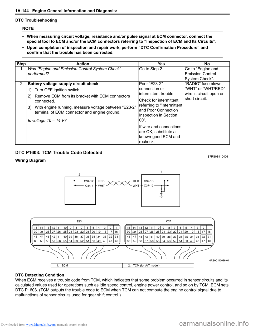
DTC P1603: TCM Trouble Code DetectedS7RS0B1104061
Wiring Diagram
DTC Detecting Condition
When ECM receives a trouble code from TCM, which indicates that some problem occurred in sensor circuits and its
calculated values used for operations such as idle speed control, engine power control, and so on by TCM, ECM sets
DTC P1603. (TCM outputs the trouble code to ECM when TCM can not compute the engine control signal due to
malfunctions of sensor circuits used for gear shift control.) Step Action Yes No
1 Was “Engine and Emission Control System Check”
performed? Go to Step 2. Go to “Engine and
Emission Control
System Check”.
2 Battery voltage supply circuit check
1) Turn OFF ignition switch.
2) Remove ECM from its br acket with ECM connectors
connected.
3) With engine running, measure voltage between “E23-2” terminal of ECM connector and engine ground.
Is voltage 10 – 14 V? Poor “E23-2”
connection or
intermittent trouble.
Check for intermittent
referring to “Intermittent
and Poor Connection
Inspection in Section
00”.
If wire and connections
are OK, substitute a
known-good ECM and
recheck.“RADIO” fuse blown,
“WHT” or “WHT/RED”
wire is circuit open or
short circuit.
E23
C37
34
1819
567
1011
17
20
47 46
495051
2122
52 16
25 9
24
14
29
55
57 54 53
59
60 58 2
262728
15
30
56 4832 31
34353637
40
42 39 38
44
45 43 41 331
1213
238
34
1819
567
1011
17
20
47 46
495051
2122
52 16
25 9
24
14
29
55
57 54 53
59
60 58 2
262728
15
30
56 4832 31
34353637
40
42 39 38
44
45 43 41 331
1213
238
1
RED
WHT
C37-13
C37-12
RED
WHTC34-7
C34-17
2
I6RS0C110026-01
1. ECM
2. TCM (for A/T model)
Page 195 of 1496
Downloaded from www.Manualslib.com manuals search engine Engine General Information and Diagnosis: 1A-145
DTC Troubleshooting
NOTE
• When measuring circuit voltage, resistance and/or pulse signal at ECM connector, connect the
special tool to ECM and/or the ECM connectors re ferring to “Inspection of ECM and Its Circuits”.
• Upon completion of inspection and repair work, perform “DTC Confirmation Procedure” and confirm that the trouble has been corrected.
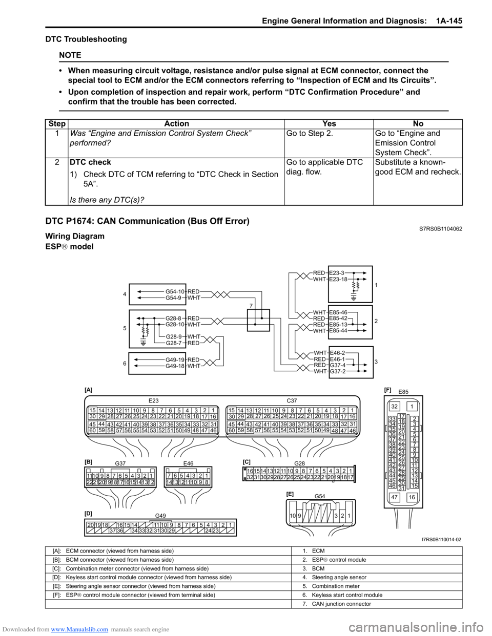
DTC P1674: CAN Communication (Bus Off Error)S7RS0B1104062
Wiring Diagram
ESP ® model
Step Action Yes No
1 Was “Engine and Emission Control System Check”
performed? Go to Step 2. Go to “Engine and
Emission Control
System Check”.
2 DTC check
1) Check DTC of TCM referring to “DTC Check in Section
5A”.
Is there any DTC(s)? Go to applicable DTC
diag. flow.
Substitute a known-
good ECM and recheck.
[F]
E85
161
15
2
3
4
5
6
7
8
9
10
11
12
13
14
17
18
19
20
21
22
23
24
25
26
27
28
29
30
31
3233
34
35
36
37
38
39
40
41
42
43
44
45
46
47
[D] 12345678910
11
141516
36 34 33 32 31 30 29 24 23
37
181920
G49
[A]
E23
C37
34
1819
567
10
11
17
20
47 46
495051
2122
52 16
25 9
24
14
29
5557 54 53
59
60 58 2
262728
15
30
56 4832 31
34353637
4042 39 38
44
45 43 41 331
1213
238
34
1819
567
10
11
17
20
47 46
495051
2122
52 16
25 9
24
14
29
5557 54 53
59
60 58 2
262728
15
30
56 4832 31
34353637
4042 39 38
44
45 43 41 331
12
13
238
[C]G28
1234567
8
910
11
1213141516
1718
19
20
212223242526272829303132
[E] G54
109 321
[B]
G37E46
1234567 1234567
8910
11
8910
11
121314 121314
1516171819202122
4
6 1
2
3
REDWHT
REDWHT
REDWHT
REDWHT
REDWHT
E23-3E23-18
E85-42E85-46
E85-13E85-44
E46-1E46-2
G37-4G37-2
REDWHT
REDWHTG49-19G49-18
5
7
WHTG54-9REDG54-10
G28-8G28-10
G28-7REDG28-9WHT
I7RS0B110014-02
[A]: ECM connector (viewed from harness side)
1. ECM
[B]: BCM connector (viewed from harness side) 2. ESP® control module
[C]: Combination meter connector (viewed from harness side) 3. BCM
[D]: Keyless start control module connector (vie wed from harness side) 4. Steering angle sensor
[E]: Steering angle sensor connector (viewed from harness side) 5. Combination meter
[F]: ESP ® control module connector (viewed from terminal side) 6. Keyless start control module
7. CAN junction connector
Page 197 of 1496
Downloaded from www.Manualslib.com manuals search engine Engine General Information and Diagnosis: 1A-147
DTC Troubleshooting
NOTE
• When measuring circuit voltage, resistance and/or pulse signal at ECM connector, connect the
special tool to ECM and/or the ECM connectors re ferring to “Inspection of ECM and Its Circuits”.
• Upon completion of inspection and repair work, perform “DTC Confirmation Procedure” and confirm that the trouble has been corrected.
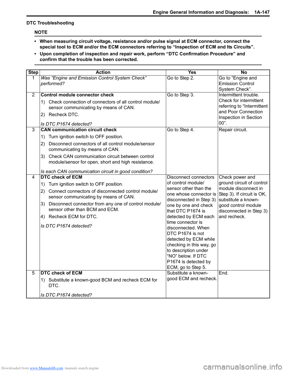
Step Action YesNo
1 Was “Engine and Emission Control System Check”
performed? Go to Step 2.
Go to “Engine and
Emission Control
System Check”.
2 Control module connector check
1) Check connection of connectors of all control module/
sensor communicating by means of CAN.
2) Recheck DTC.
Is DTC P1674 detected? Go to Step 3.
Intermittent trouble.
Check for intermittent
referring to “Intermittent
and Poor Connection
Inspection in Section
00”.
3 CAN communication circuit check
1) Turn ignition switch to OFF position.
2) Disconnect connectors of all control module/sensor
communicating by means of CAN.
3) Check CAN communication circuit between control module/sensor for open, short and high resistance.
Is each CAN communication circuit in good condition? Go to Step 4.
Repair circuit.
4 DTC check of ECM
1) Turn ignition switch to OFF position.
2) Connect connectors of di sconnected control module/
sensor communicating by means of CAN.
3) Disconnect connector from any one of control module/ sensor other than BCM and ECM.
4) Recheck ECM for DTC.
Is DTC P1674 detected? Disconnect connectors
of control module/
sensor other than the
one whose connector is
disconnected in Step 3)
one by one and check
that DTC P1674 is
detected by ECM each
time connector is
disconnected. When
DTC P1674 is not
detected by ECM while
checking in this way, go
to description under
“NO” below. If DTC
P1674 is detected by
ECM, go to Step 5.Check power and
ground circuit of control
module disconnect in
Step 3). If circuit is OK,
substitute a known-
good control module
disconnected in Step 3)
and recheck.
5 DTC check of ECM
1) Substitute a known-good BCM and recheck ECM for
DTC.
Is DTC P1674 detected? Substitute a known-
good ECM and recheck.
End.
Page 204 of 1496
Downloaded from www.Manualslib.com manuals search engine 1A-154 Engine General Information and Diagnosis:
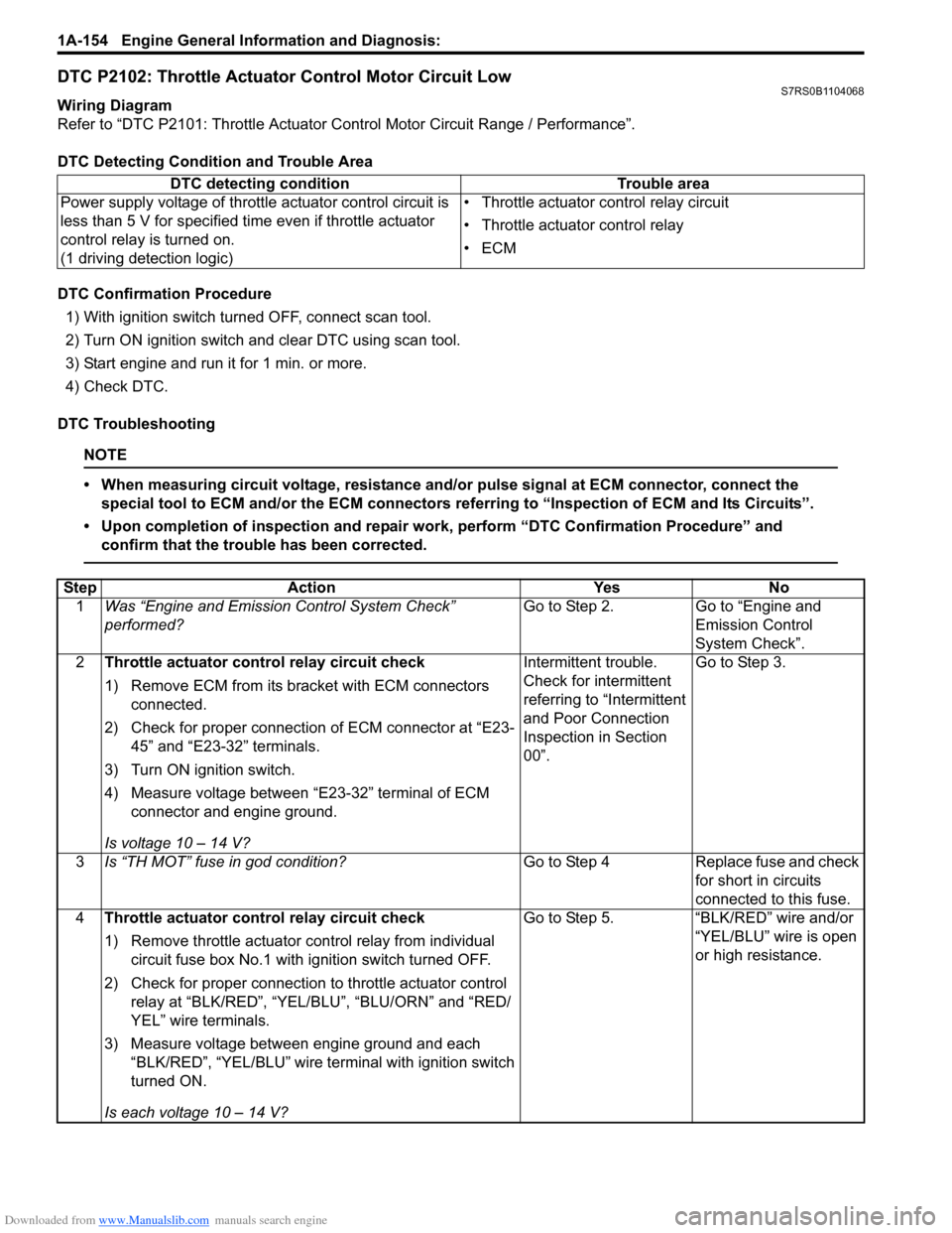
DTC P2102: Throttle Actuator Control Motor Circuit LowS7RS0B1104068
Wiring Diagram
Refer to “DTC P2101: Throttle Actuator Control Motor Circuit Range / Performance”.
DTC Detecting Condition and Trouble Area
DTC Confirmation Procedure 1) With ignition switch turned OFF, connect scan tool.
2) Turn ON ignition switch and clear DTC using scan tool.
3) Start engine and run it for 1 min. or more.
4) Check DTC.
DTC Troubleshooting
NOTE
• When measuring circuit voltage, resistance and/ or pulse signal at ECM connector, connect the
special tool to ECM and/or the ECM connectors re ferring to “Inspection of ECM and Its Circuits”.
• Upon completion of inspection and repair work, perform “DTC Confirmation Procedure” and confirm that the trouble has been corrected.
DTC detecting condition Trouble area
Power supply voltage of throttle actuator control circuit is
less than 5 V for specified time even if throttle actuator
control relay is turned on.
(1 driving detection logic) • Throttle actuator control relay circuit
• Throttle actuator control relay
•ECM
Step
Action YesNo
1 Was “Engine and Emission Control System Check”
performed? Go to Step 2.
Go to “Engine and
Emission Control
System Check”.
2 Throttle actuator cont rol relay circuit check
1) Remove ECM from its br acket with ECM connectors
connected.
2) Check for proper connection of ECM connector at “E23- 45” and “E23-32” terminals.
3) Turn ON ignition switch.
4) Measure voltage between “E23-32” terminal of ECM connector and engine ground.
Is voltage 10 – 14 V? Intermittent trouble.
Check for intermittent
referring to “Intermittent
and Poor Connection
Inspection in Section
00”.
Go to Step 3.
3 Is “TH MOT” fuse in god condition? Go to Step 4Replace fuse and check
for short in circuits
connected to this fuse.
4 Throttle actuator cont rol relay circuit check
1) Remove throttle actuator co ntrol relay from individual
circuit fuse box No.1 with ignition switch turned OFF.
2) Check for proper connection to throttle actuator control relay at “BLK/RED”, “YEL/BLU”, “BLU/ORN” and “RED/
YEL” wire terminals.
3) Measure voltage between engine ground and each “BLK/RED”, “YEL/BLU” wire terminal with ignition switch
turned ON.
Is each voltage 10 – 14 V? Go to Step 5.
“BLK/RED” wire and/or
“YEL/BLU” wire is open
or high resistance.
Page 205 of 1496
Downloaded from www.Manualslib.com manuals search engine Engine General Information and Diagnosis: 1A-155
DTC P2103: Throttle Actuator Control Motor Circuit HighS7RS0B1104069
Wiring Diagram
Refer to “DTC P2101: Throttle Actuator Control Motor Circuit Range / Performance”.
DTC Detecting Condition and Trouble Area
DTC Confirmation Procedure 1) With ignition switch turned OFF, connect scan tool.
2) Turn ON ignition switch and clear DTC using scan tool.
3) Ignition switch turned OFF for 20 sec. or more.
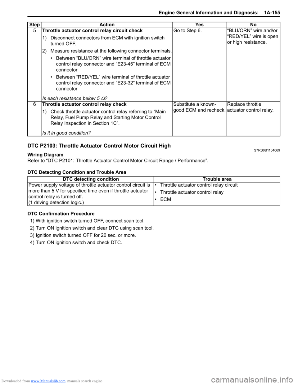
4) Turn ON ignition switch and check DTC. 5
Throttle actuator cont rol relay circuit check
1) Disconnect connectors from ECM with ignition switch turned OFF.
2) Measure resistance at the following connector terminals. • Between “BLU/ORN” wire termin al of throttle actuator
control relay connector and “E23-45” terminal of ECM
connector
• Between “RED/YEL” wire terminal of throttle actuator control relay connector and “E23-32” terminal of ECM
connector
Is each resistance below 5
Ω? Go to Step 6. “BLU/ORN” wire and/or
“RED/YEL” wire is open
or high resistance.
6 Throttle actuator control relay check
1) Check throttle actuator control relay referring to “Main Relay, Fuel Pump Relay an d Starting Motor Control
Relay Inspection in Section 1C”.
Is it in good condition? Substitute a known-
good ECM and recheck.
Replace throttle
actuator control relay.
Step
Action YesNo
DTC detecting condition Trouble area
Power supply voltage of throttle actuator control circuit is
more than 5 V for specified time even if throttle actuator
control relay is turned off.
(1 driving detection logic.) • Throttle actuator control relay circuit
• Throttle actuator control relay
•ECM
Page 208 of 1496
Downloaded from www.Manualslib.com manuals search engine 1A-158 Engine General Information and Diagnosis:
DTC Confirmation Procedure1) With ignition switch turned OFF, connect scan tool.
2) Turn ON ignition switch and clear DTC using scan tool.
3) Keep the accelerator pedal at idle position for 2 seconds.
4) Keep the accelerator pedal at fully depressed position for 2 seconds.
5) Repeat Step 3) and 4) for 3 times.
6) Check DTC.
DTC Troubleshooting
NOTE
• When measuring circuit voltage, resistance and/ or pulse signal at ECM connector, connect the
special tool to ECM and/or the ECM connectors re ferring to “Inspection of ECM and Its Circuits”.
• Upon completion of inspection and repair work, perform “DTC Confirmation Procedure” and confirm that the trouble has been corrected.
Step Action YesNo
1 Was “Engine and Emission Control System Check”
performed? Go to Step 2.
Go to “Engine and
Emission Control
System Check”.
2 Electric throttle body assembly system check
1) Connect scan tool to DLC with ignition switch turned
OFF.
2) Turn ON ignition switch, check each voltage of “TP Sensor 1 Volt” and “TP Sensor 2 Volt” displayed on scan
tool when accelerator pedal is idle position and fully
depressed.
Is displayed each TP sensor value as described voltage in
“Scan Tool Data”? Intermittent trouble.
Check for intermittent
referring to “Intermittent
and Poor Connection
Inspection in Section
00”.
Go to Step 3.
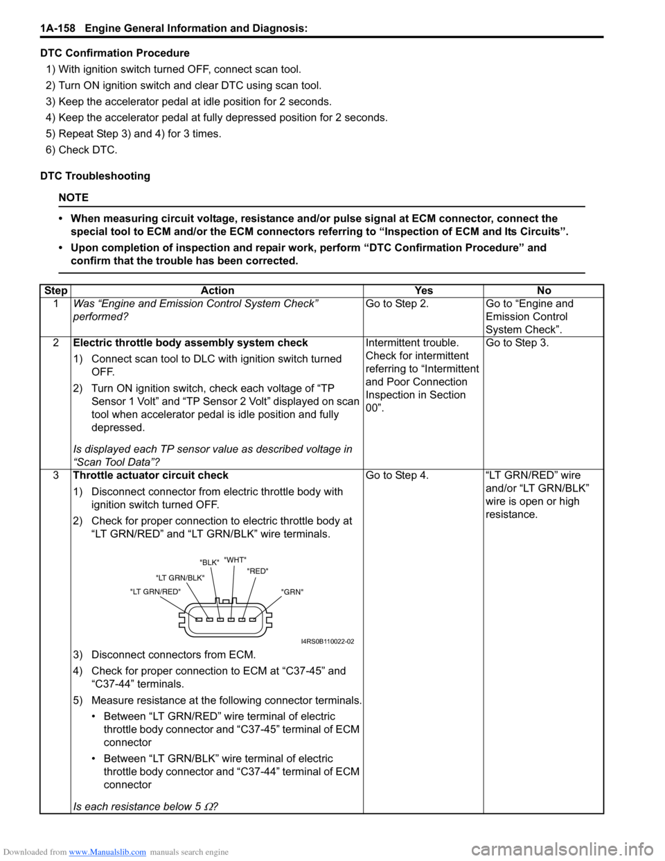
3 Throttle actuator circuit check
1) Disconnect connector from electric throttle body with
ignition switch turned OFF.
2) Check for proper connection to electric throttle body at “LT GRN/RED” and “LT G RN/BLK” wire terminals.
3) Disconnect connectors from ECM.
4) Check for proper connection to ECM at “C37-45” and “C37-44” terminals.
5) Measure resistance at the following connector terminals. • Between “LT GRN/RED” wire terminal of electric throttle body connector and “C37-45” terminal of ECM
connector
• Between “LT GRN/BLK” wire terminal of electric throttle body connector and “C37-44” terminal of ECM
connector
Is each resistance below 5
Ω? Go to Step 4. “LT GRN/RED” wire
and/or “LT GRN/BLK”
wire is open or high
resistance.
"GRN"
"RED"
"WHT"
"BLK"
"LT GRN/BLK"
"LT GRN/RED"
I4RS0B110022-02
Page 209 of 1496
Downloaded from www.Manualslib.com manuals search engine Engine General Information and Diagnosis: 1A-159
DTC P2122: Throttle / Pedal Position Sensor / Switch “D” (Main) Circuit Low InputS7RS0B1104072
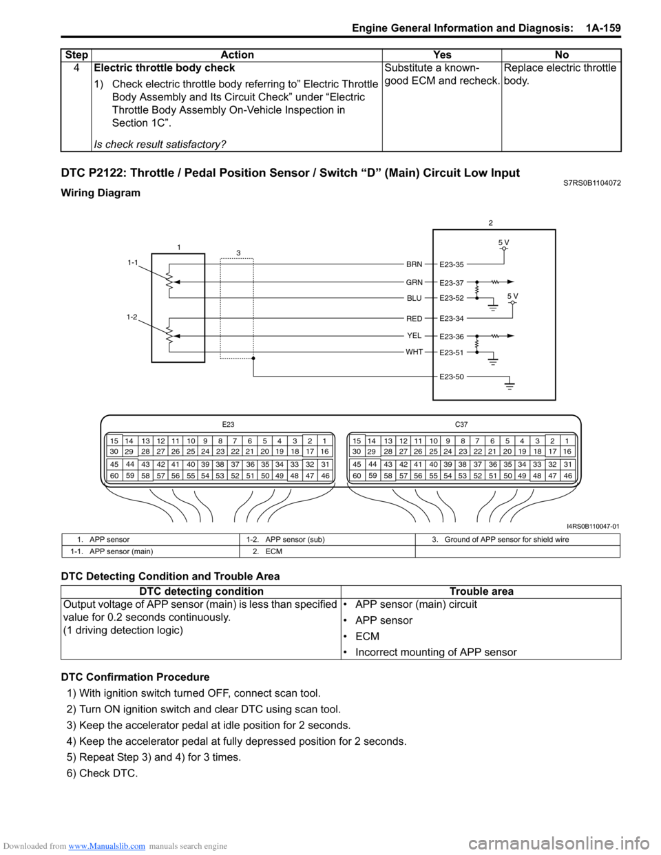
Wiring Diagram
DTC Detecting Condition and Trouble Area
DTC Confirmation Procedure1) With ignition switch turned OFF, connect scan tool.
2) Turn ON ignition switch and clear DTC using scan tool.
3) Keep the accelerator pedal at idle position for 2 seconds.
4) Keep the accelerator pedal at fully depressed position for 2 seconds.
5) Repeat Step 3) and 4) for 3 times.
6) Check DTC. 4
Electric throttle body check
1) Check electric throttle body referring to” Electric Throttle
Body Assembly and Its Circuit Check” under “Electric
Throttle Body Assembly On-Vehicle Inspection in
Section 1C”.
Is check result satisfactory? Substitute a known-
good ECM and recheck.
Replace electric throttle
body.
Step Action Yes No
E23
C37
34
1819
567
1011
17
20
47 46
495051
2122
52 16
25 9
24
14
29
55
57 54 53
59
60 58 2
262728
15
30
56 4832 31
34353637
40
42 39 38
44
45 43 41 331
1213
238
34
1819
567
1011
17
20
47 46
495051
2122
52 16
25 9
24
14
29
55
57 54 53
59
60 58 2
262728
15
30
56 48 32 31
34353637
40
42 39 38
44
45 43 41 331
1213
238
BRN
GRN
BLU
RED
YEL
WHT
E23-35
E23-37
E23-52
E23-34
E23-36
E23-51
E23-50 5 V
5 V
1
1-1 3 2
1-2
I4RS0B110047-01
1. APP sensor
1-2. APP sensor (sub) 3. Ground of APP sensor for shield wire
1-1. APP sensor (main) 2. ECM
DTC detecting condition Trouble area
Output voltage of APP sensor (main) is less than specified
value for 0.2 seconds continuously.
(1 driving detection logic) • APP sensor (main) circuit
• APP sensor
•ECM
• Incorrect mounting of APP sensor
Page 210 of 1496
Downloaded from www.Manualslib.com manuals search engine 1A-160 Engine General Information and Diagnosis:
DTC Troubleshooting
NOTE
• When measuring circuit voltage, resistance and/or pulse signal at ECM connector, connect the
special tool to ECM and/or the ECM connectors re ferring to “Inspection of ECM and Its Circuits”.
• Upon completion of inspection and repair work, perform “DTC Confirmation Procedure” and confirm that the trouble has been corrected.
Step Action YesNo
1 Was “Engine and Emission Control System Check”
performed? Go to Step 2.
Go to “Engine and
Emission Control
System Check”.
2 APP sensor mounting check
1) Check that APP sensor has been mounted to vehicle
body properly (no pinched floor carpet, etc.).
It is OK? Go to Step 3.
Reinstall APP sensor
properly referring to
“APP Sensor Assembly
Removal and
Installation in Section
1C”.
3 APP sensor (main) and its circuit check
1) Connect scan tool to DLC with ignition switch turned
OFF.
2) Turn ON ignition switch, check “APP Sensor 1 Volt” displayed on scan tool.
Is displayed voltage below 0.384 V? Go to Step 4.
Intermittent trouble.
Check for intermittent
referring to “Intermittent
and Poor Connection
Inspection in Section
00”.
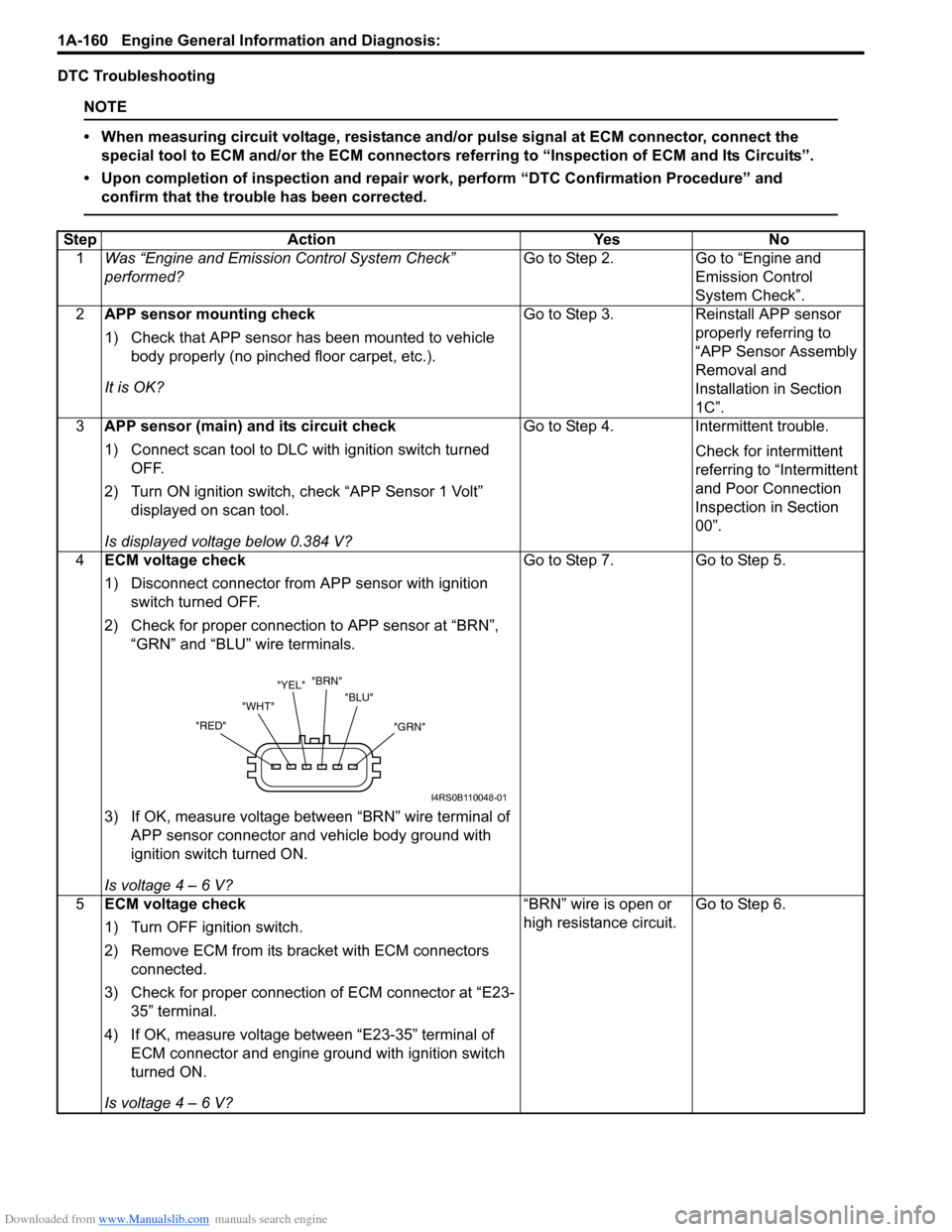
4 ECM voltage check
1) Disconnect connector from APP sensor with ignition
switch turned OFF.
2) Check for proper connection to APP sensor at “BRN”, “GRN” and “BLU” wire terminals.
3) If OK, measure voltage between “BRN” wire terminal of APP sensor connector and vehicle body ground with
ignition switch turned ON.
Is voltage 4 – 6 V? Go to Step 7.
Go to Step 5.
5 ECM voltage check
1) Turn OFF ignition switch.
2) Remove ECM from its br acket with ECM connectors
connected.
3) Check for proper connection of ECM connector at “E23- 35” terminal.
4) If OK, measure voltage between “E23-35” terminal of ECM connector and engine ground with ignition switch
turned ON.
Is voltage 4 – 6 V? “BRN” wire is open or
high resistance circuit.
Go to Step 6.
"GRN"
"BLU"
"BRN"
"YEL"
"WHT"
"RED"
I4RS0B110048-01
Page 211 of 1496
Downloaded from www.Manualslib.com manuals search engine Engine General Information and Diagnosis: 1A-161
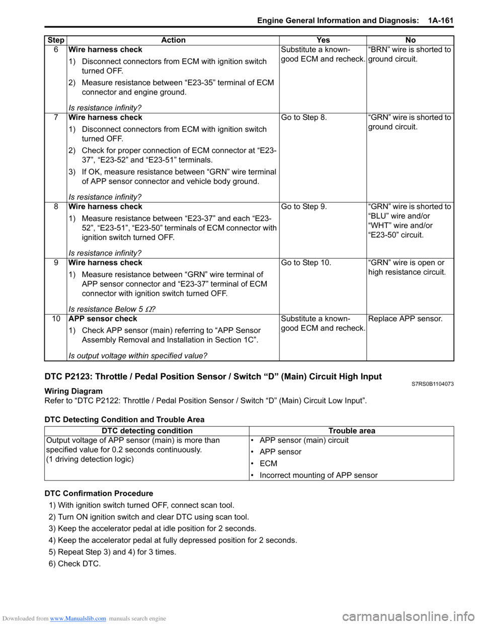
DTC P2123: Throttle / Pedal Position Sensor / Switch “D” (Main) Circuit High InputS7RS0B1104073
Wiring Diagram
Refer to “DTC P2122: Throttle / Pedal Position Sensor / Switch “D” (Main) Circuit Low Input”.
DTC Detecting Condition and Trouble Area
DTC Confirmation Procedure 1) With ignition switch turned OFF, connect scan tool.
2) Turn ON ignition switch and clear DTC using scan tool.
3) Keep the accelerator pedal at idle position for 2 seconds.
4) Keep the accelerator pedal at fully depressed position for 2 seconds.
5) Repeat Step 3) and 4) for 3 times.
6) Check DTC. 6
Wire harness check
1) Disconnect connectors from ECM with ignition switch
turned OFF.
2) Measure resistance between “E23-35” terminal of ECM connector and engine ground.
Is resistance infinity? Substitute a known-
good ECM and recheck.
“BRN” wire is shorted to
ground circuit.
7 Wire harness check
1) Disconnect connectors from ECM with ignition switch
turned OFF.
2) Check for proper connection of ECM connector at “E23- 37”, “E23-52” and “E23-51” terminals.
3) If OK, measure resistance between “GRN” wire terminal of APP sensor connector and vehicle body ground.
Is resistance infinity? Go to Step 8. “GRN” wire is shorted to
ground circuit.
8 Wire harness check
1) Measure resistance between “E23-37” and each “E23-
52”, “E23-51”, “E23-50” terminals of ECM connector with
ignition switch turned OFF.
Is resistance infinity? Go to Step 9. “GRN” wire is shorted to
“BLU” wire and/or
“WHT” wire and/or
“E23-50” circuit.
9 Wire harness check
1) Measure resistance between “GRN” wire terminal of
APP sensor connector and “E23-37” terminal of ECM
connector with ignition switch turned OFF.
Is resistance Below 5
Ω? Go to Step 10. “GRN” wire is open or
high resistance circuit.
10 APP sensor check
1) Check APP sensor (main) re ferring to “APP Sensor
Assembly Removal and Inst allation in Section 1C”.
Is output voltage within specified value? Substitute a known-
good ECM and recheck.
Replace APP sensor.
Step Action Yes No
DTC detecting condition
Trouble area
Output voltage of APP sensor (main) is more than
specified value for 0.2 seconds continuously.
(1 driving detection logic) • APP sensor (main) circuit
• APP sensor
•ECM
• Incorrect mounting of APP sensor