special tools SUZUKI SWIFT 2007 2.G Service Workshop Manual
[x] Cancel search | Manufacturer: SUZUKI, Model Year: 2007, Model line: SWIFT, Model: SUZUKI SWIFT 2007 2.GPages: 1496, PDF Size: 34.44 MB
Page 1165 of 1496
Downloaded from www.Manualslib.com manuals search engine Air Bag System: 8B-127
Recommended Service MaterialS7RS0B8208002
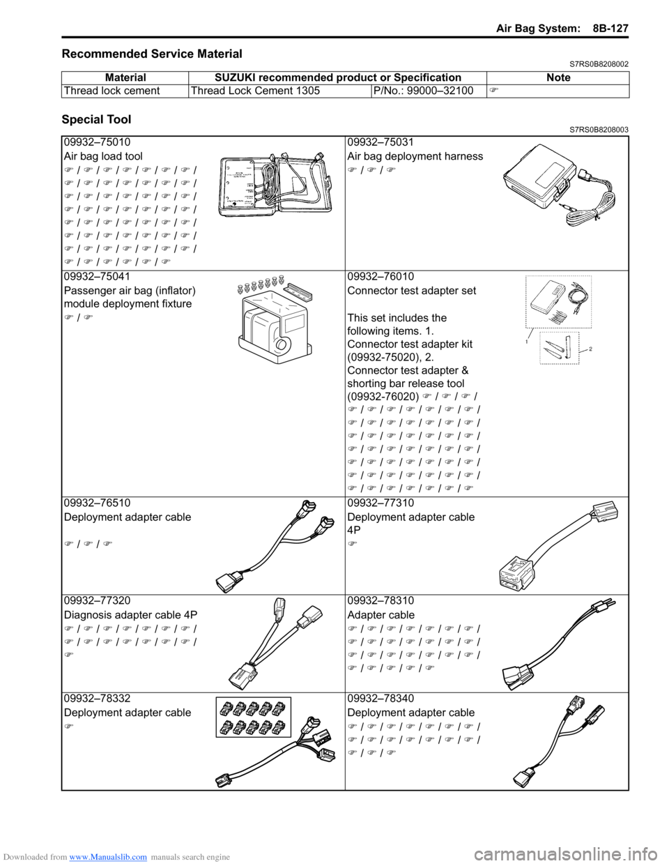
Special ToolS7RS0B8208003
MaterialSUZUKI recommended product or Specification Note
Thread lock cement Thread Lock Cement 1305 P/No.: 99000–32100 �)
09932–7501009932–75031
Air bag load tool Air bag deployment harness
�) / �) / �) / �) / �) / �) / �) /
�) / �) / �) / �) / �) / �) / �) /
�) / �) / �) / �) / �) / �) / �) /
�) / �) / �) / �) / �) / �) / �) /
�) / �) / �) / �) / �) / �) / �) /
�) / �) / �) / �) / �) / �) / �) /
�) / �) / �) / �) / �) / �) / �) /
�) / �) / �) / �) / �) / �) �)
/ �) / �)
0
9932–75041 09932–76010
Passenger air bag (inflator)
module deployment fixture Connector test adapter set
�) / �) This set includes the
following items. 1.
Connector test adapter kit
(09932-75020), 2.
Connector test adapter &
shorting bar release tool
(09932-76020) �) / �) / �) /
�) / �) / �) / �) / �) / �) / �) /
�) / �) / �) / �) / �) / �) / �) /
�) / �) / �) / �) / �) / �) / �) /
�) / �) / �) / �) / �) / �) / �) /
�) / �) / �) / �) / �) / �) / �) /
�) / �) / �) / �) / �) / �) / �) /
�) / �) / �) / �) / �) / �) / �)
0
9932–76510 09932–77310
Deployment adapter cable Deployment adapter cable
4P
�) / �) / �)�)
09932–77320 09932–78310
Diagnosis adapter cable 4P Adapter cable
�) / �) / �) / �) / �) / �) / �) /
�) / �) / �) / �) / �) / �) / �) /
�) �)
/ �) / �) / �) / �) / �) / �) /
�) / �) / �) / �) / �) / �) / �) /
�) / �) / �) / �) / �) / �) / �) /
�) / �) / �) / �) / �)
0
9932–78332 09932–78340
Deployment adapter cable Deployment adapter cable
�)�) / �) / �) / �) / �) / �) / �) /
�) / �) / �) / �) / �) / �) / �) /
�) / �) / �)
Page 1169 of 1496

Downloaded from www.Manualslib.com manuals search engine Table of Contents 9-iii
Door Switch (Front / Rear Door) Inspection ...... 9C-17
Rear End Door Switch Inspection ..................... 9C-17
Outside Air Temperature Sensor Removal and Installation (If Equipped) .......................... 9C-17
Outside Air Temperature Sensor Inspection (If Equipped) ................................................... 9C-17
Instrument Panel Removal and Installation....... 9C-18
Information Display (Clock) Removal and Installation ....................................................... 9C-19
Audio Unit Removal and In stallation ................. 9C-19
Front Speaker Removal and Installation ........... 9C-19
Rear Speaker Removal and Installation............ 9C-20
Horn Removal and Installation .......................... 9C-20
Horn Inspection ................................................. 9C-20
Horn Relay Inspection ....................................... 9C-20
Antenna Amplifier Removal and Installation ..... 9C-21
Remote Audio Control Switch Removal and Installation (If Equipped) ................................. 9C-21
Remote Audio Control Switch Inspection (If Equipped)........................................................ 9C-22
Vehicle Speed Signal Inspection (For Audio Unit) (If Equipped) ........................................... 9C-22
Specifications ..................................................... 9C-22
Tightening Torque Specifications ...................... 9C-22
Wipers / Washers............ ......................... 9D-1
Diagnostic Information and Procedures ............ 9D-1
Front Wiper and Washer Symptom Diagnosis .... 9D-1
Rear Wiper and Washer Symptom Diagnosis..... 9D-1
Repair Instructions .............................................. 9D-2 Wipers and Washers Components ..................... 9D-2
Washer Tank and Washer Pump Removal and Installation .................................................. 9D-3
Washer Pump Inspection .................................... 9D-3
Windshield Wiper Removal and Installation ........ 9D-4
Windshield Wiper Motor Inspection..................... 9D-5
Rear Wiper Removal and Installation.................. 9D-6
Rear Wiper Motor Inspection .............................. 9D-7
Windshield Wiper and Washer Switch Removal and Installation................................... 9D-7
Windshield Wiper and Washer Switch Inspection.......................................................... 9D-8
Rear Wiper and Washer Switch Removal and Installation ......................................................... 9D-9
Rear Wiper and Washer Switch Inspection......... 9D-9
Rear Wiper Relay Removal and Installation ..... 9D-10
Rear Wiper Relay Inspection ............................ 9D-10
Specifications ..................................................... 9D-10
Tightening Torque Specifications ...................... 9D-10
Glass / Windows / Mirrors.. ..................... 9E-1
General Description ............................................. 9E-1
Rear End Door Window Defogger System Description ........................................................ 9E-1
Windshield Construction ..................................... 9E-1
Diagnostic Information and Procedures ............ 9E-2 Rear End door Window Defogger Symptom Diagnosis .......................................................... 9E-2 Power Window Control System Symptom
Diagnosis .......................................................... 9E-2
Power Door Mirror Control System Symptom Diagnosis .......................................................... 9E-3
Door Mirror Heater Symptom Diagnosis (If
Equipped) .......................................................... 9E-3
Repair Instructions ........... ................................... 9E-4
Windshield Removal and In stallation .................. 9E-4
Front Door Window Components ........................ 9E-8
Front Door Glass Removal and Installation ........ 9E-8
Front Door Window Re gulator Removal and
Installation ......................................................... 9E-9
Front Door Window Regula tor Inspection ......... 9E-10
Rear Door Window Components ...................... 9E-10
Rear Door Glass Removal and Installation ....... 9E-11
Rear Door Window Regulator Removal and Installation ....................................................... 9E-12
Rear Door Window Regulato r Inspection .......... 9E-12
Rear End Door Window Components ............... 9E-13
Rear End Door Glass Removal and Installation ....................................................... 9E-13
Rear End Door Window Defogger Switch Inspection ........................................................ 9E-14
Rear End Door Window Defogger Relay Inspection ........................................................ 9E-14
Rear End Door Window Defogger Wire Inspection ........................................................ 9E-15
Rear End Door Window Defogger Wire
Repair.............................................................. 9E-15
Power Window Main Switch Inspection ............ 9E-16
Power Window Sub Switch Inspection .............. 9E-17
Door Mirror Components.. ................................. 9E-18
Door Mirror Removal and In stallation................ 9E-18
Power Door Mirror Switch Inspection ................ 9E-18
Power Door Mirror Actuator Inspection ............. 9E-19
Door Mirror Heater Switch Inspection (If Equipped) ........................................................ 9E-19
Door Mirror Heater Inspec tion (If Equipped) ..... 9E-19
Special Tools and Equipmen t ........................... 9E-19
Recommended Service Material ....................... 9E-19
Security and Locks......... ..........................9F-1
General Description ............................................. 9F-1
Key Coding Construction .................................... 9F-1
Rear End Door Opener System Description ....... 9F-1
Component Location ............ ............................... 9F-2
Power Door Lock and Keyless Entry System
Component Location ......................................... 9F-2
Diagnostic Information and Procedures ............ 9F-3 Power Door Lock System Symptom Diagnosis .......................................................... 9F-3
Power Door Lock System Operation Inspection .......................................................... 9F-3
Keyless Entry System Symptom Diagnosis (If
Equipped) .......................................................... 9F-4
Keyless Entry System Operation Inspection ....... 9F-5
Door Lock Function of Keyless Start System Symptom Diagnosis (If Equipped)..................... 9F-5
Page 1170 of 1496

Downloaded from www.Manualslib.com manuals search engine 9-iv Table of Contents
Rear End Door Opener System Symptom Diagnosis .......................................................... 9F-5
Rear End Door Opener System Operation Inspection .......................................................... 9F-5
Repair Instructions ........... ................................... 9F-6
Front Door Lock Assembly Components ............ 9F-6
Front Door Lock Assembly Removal and Installation ......................................................... 9F-6
Front Door Lock Assembly Inspection ................ 9F-8
Power Door Lock Switch In spection.................... 9F-8
Door Key Cylinder Switch Inspection .................. 9F-8
Power Door Lock Actuator Inspection ................. 9F-9
Rear Door Lock Assembly Components ........... 9F-10
Rear Door Lock Assembly Removal and Installation ....................................................... 9F-10
Rear Door Lock Assembly Inspection ............... 9F-10
Rear End Door Lock Assembly Components.... 9F-11
Rear End Door Lock Assembly Removal and Installation ....................................................... 9F-11
Rear End Door Lock Assembly Inspection........ 9F-12
Rear End Door Opener Switch Inspection ........ 9F-12
Replacement of Transmitte r Battery ................. 9F-13
Programming Transmitter Code for Keyless Entry System (Vehicle without Keyless Start
System) ........................................................... 9F-13
Keyless Entry Answer Back Function
Change-over Procedure (If Equipped) ............ 9F-14
Keyless Entry Receiver Removal and
Installation ....................................................... 9F-14
Keyless Entry Receiver and Its Circuit Inspection ........................................................ 9F-15
Specifications .... ................................................. 9F-16
Tightening Torque Specifications ...................... 9F-16
Special Tools and Equipmen t ........................... 9F-16
Recommended Service Material ....................... 9F-16
Seats ............. ............................................ 9G-1
Repair Instructions ............................................. 9G-1
Front Seat Components ..................................... 9G-1
Front Seat Removal and In stallation .................. 9G-2
Rear Seat Components...................................... 9G-3
Rear Seat Removal and Installation................... 9G-4
Specifications .... .................................................. 9G-4
Tightening Torque Specifications ....................... 9G-4
Special Tools and Equipmen t ............................ 9G-4
Recommended Service Material ........................ 9G-4
Interior Trim ................. ............................ 9H-1
Repair Instructions ............ ..................................9H-1
Floor Carpet Removal and Installation ................9H-1
Head Lining Removal and Installation.................9H-1
Console Box Components ..................................9H-2
Specifications ..................... ..................................9H-3
Tightening Torque Specifications ........................9H-3
Hood / Fenders / Doors ...... ...................... 9J-1
Repair Instructions ............ .................................. 9J-1
Hood Removal and Installation ........................... 9J-1
Hood Inspection and Adjustment ........................ 9J-1
Front Fender Components .................................. 9J-2
Front Fender Removal and Installation ............... 9J-2
Front Door Assembly Comp onents ..................... 9J-3
Front Door Assembly Removal and Installation ......................................................... 9J-3
Rear Door Assembly Components...................... 9J-5
Rear Door Assembly Removal and Installation ......................................................... 9J-5
Rear End Door Assembly Components .............. 9J-6
Rear End Door Assembly Removal and Installation ......................................................... 9J-6
Specifications ..................... .................................. 9J-8
Tightening Torque Specifications ........................ 9J-8
Special Tools and Equipmen t ............................. 9J-8
Recommended Service Material ......................... 9J-8
Body Structure............... .......................... 9K-1
Repair Instructions ............ ..................................9K-1
Front Bumper and Rear Bumper Components .... 9K-1
Cowl Top Components........................................ 9K-2
Specifications ..................... ..................................9K-3
Body Dimensions ................................................ 9K-3
Panel Clearance................................................ 9K-10
Paint / Coatings ............. ...........................9L-1
General Description ............................................. 9L-1
Anti-Corrosion Treatment Construction............... 9L-1
Plastic Parts Finishing ......................................... 9L-2
Component Location ............ ............................... 9L-3
Sealant Application Areas ................................... 9L-3
Under Coating Application Areas ........................ 9L-8
Anti-Corrosion Compound Application Area ..... 9L-10
Exterior Trim ...... ...................................... 9M-1
Repair Instructions ......... .................................... 9M-1
Roof Molding Components................................. 9M-1
Splash Guard (If Equipped) Components .......... 9M-2
Page 1328 of 1496
Downloaded from www.Manualslib.com manuals search engine 9E-1 Glass / Windows / Mirrors:
Body, Cab and Accessories
Glass / Windows / Mirrors
General Description
Rear End Door Window Defogger System DescriptionS7RS0B9501001
The rear end door window defogger is controlled by BCM. For the BCM description refer to “BCM General Description
in Section 10B”.
Windshield ConstructionS7RS0B9501002
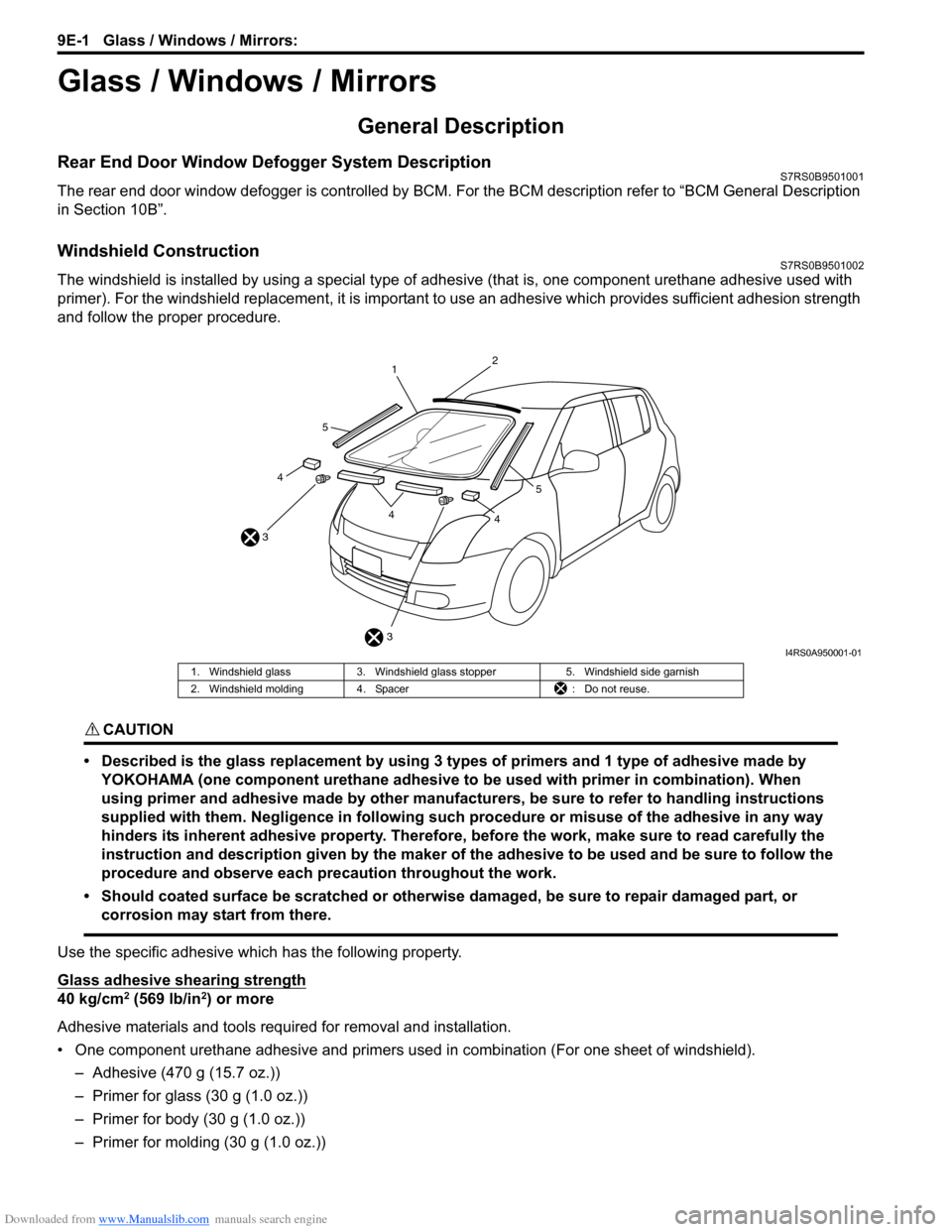
The windshield is installed by using a special type of adhesive (that is, one component urethane adhesive used with
primer). For the windshield replacement, it is important to use an adhesive which provides sufficient adhesion strength
and follow the proper procedure.
CAUTION!
• Described is the glass replacement by using 3 types of primers and 1 type of adhesive made by YOKOHAMA (one component urethane adhesive to be used with primer in combination). When
using primer and adhesive made by other manufacturers, be sure to refer to handling instructions
supplied with them. Negligence in following such procedure or misuse of the adhesive in any way
hinders its inherent adhesive property. Therefore, before the work, make sure to read carefully the
instruction and description given by the maker of the adhesive to be used and be sure to follow the
procedure and observe each precaution throughout the work.
• Should coated surface be scratched or otherwise damaged, be sure to repair damaged part, or corrosion may start from there.
Use the specific adhesive which has the following property.
Glass adhesive shearing strength
40 kg/cm2 (569 lb/in2) or more
Adhesive materials and tools required for removal and installation.
• One component urethane adhesive and primers used in combination (For one sheet of windshield). – Adhesive (470 g (15.7 oz.))
– Primer for glass (30 g (1.0 oz.))
– Primer for body (30 g (1.0 oz.))
– Primer for molding (30 g (1.0 oz.))
3
3 1
2
44
4
5
5
I4RS0A950001-01
1. Windshield glass
3. Windshield glass stopper 5. Windshield side garnish
2. Windshield molding 4. Spacer : Do not reuse.
Page 1346 of 1496
Downloaded from www.Manualslib.com manuals search engine 9E-19 Glass / Windows / Mirrors:
Power Door Mirror Actuator InspectionS7RS0B9506021
1) Remove front door trim referring to step 1) to 3) of “Front Door Glass Removal and Installation”.
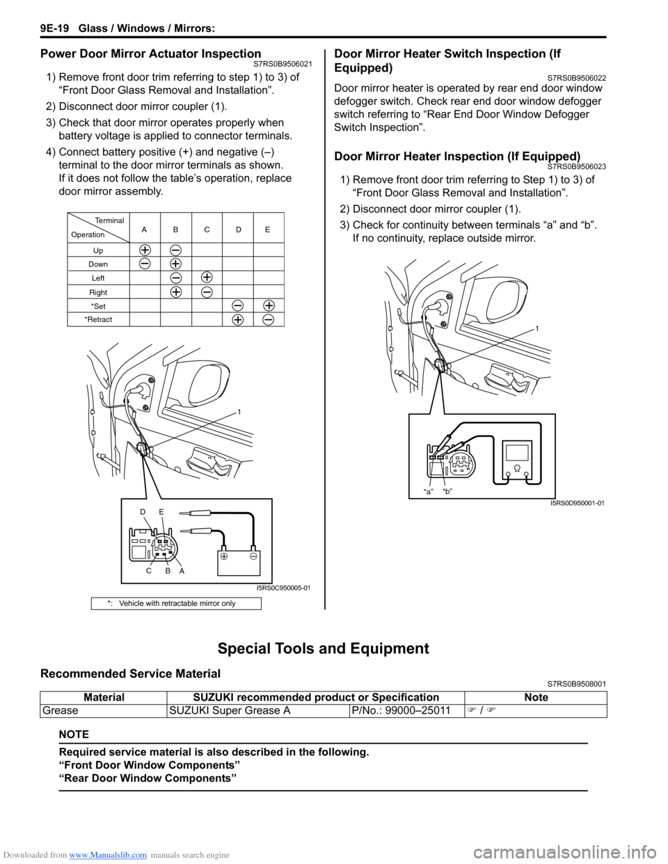
2) Disconnect door mirror coupler (1).
3) Check that door mirror operates properly when battery voltage is applied to connector terminals.
4) Connect battery positive (+) and negative (–) terminal to the door mirror terminals as shown.
If it does not follow the table’s operation, replace
door mirror assembly.
Door Mirror Heater Switch Inspection (If
Equipped)
S7RS0B9506022
Door mirror heater is operated by rear end door window
defogger switch. Check rear end door window defogger
switch referring to “Rear End Door Window Defogger
Switch Inspection”.
Door Mirror Heater Inspection (If Equipped)S7RS0B9506023
1) Remove front door trim refe rring to Step 1) to 3) of
“Front Door Glass Removal and Installation”.
2) Disconnect door mirror coupler (1).
3) Check for continuity between terminals “a” and “b”. If no continuity, replace outside mirror.
Special Tools and Equipment
Recommended Service MaterialS7RS0B9508001
NOTE
Required service material is also described in the following.
“Front Door Window Components”
“Rear Door Window Components”
*: Vehicle with retractable mirror only
Operation
Terminal
Up
Down
Left
RightCBA
1
C B
A
*Set
*Retract
DE
DE
I5RS0C950005-01
1
“a” “b”
I5RS0D950001-01
Material
SUZUKI recommended product or Specification Note
Grease SUZUKI Super Grease A P/No.: 99000–25011�) / �)
Page 1362 of 1496
Downloaded from www.Manualslib.com manuals search engine 9F-16 Security and Locks:
Specifications
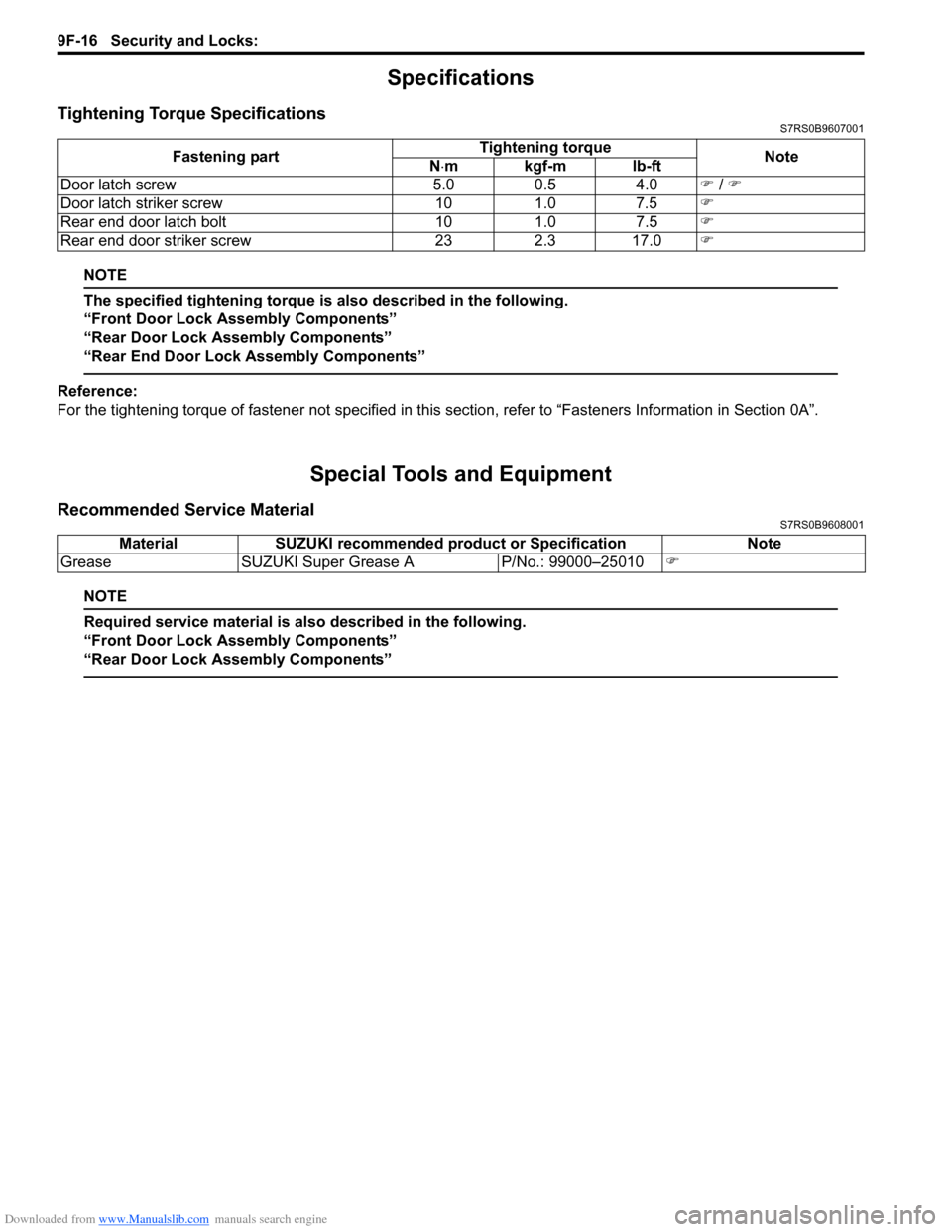
Tightening Torque SpecificationsS7RS0B9607001
NOTE
The specified tightening torque is also described in the following.
“Front Door Lock Assembly Components”
“Rear Door Lock Assembly Components”
“Rear End Door Lock Assembly Components”
Reference:
For the tightening torque of fastener not specified in this section, refer to “Fasteners Information in Section 0A”.
Special Tools and Equipment
Recommended Service MaterialS7RS0B9608001
NOTE
Required service material is also described in the following.
“Front Door Lock Assembly Components”
“Rear Door Lock Assembly Components”
Fastening part Tightening torque
Note
N ⋅mkgf-mlb-ft
Door latch screw 5.0 0.5 4.0 �) / �)
Door latch striker screw 10 1.0 7.5 �)
Rear end door latch bolt 10 1.0 7.5 �)
Rear end door striker screw 23 2.3 17.0 �)
MaterialSUZUKI recommended product or Specification Note
Grease SUZUKI Super Grease A P/No.: 99000–25010�)
Page 1366 of 1496
Downloaded from www.Manualslib.com manuals search engine 9G-4 Seats:
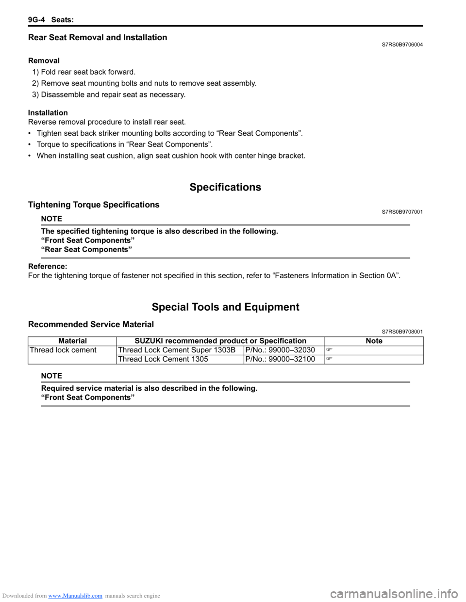
Rear Seat Removal and InstallationS7RS0B9706004
Removal1) Fold rear seat back forward.
2) Remove seat mounting bolts and nuts to remove seat assembly.
3) Disassemble and repair seat as necessary.
Installation
Reverse removal procedure to install rear seat.
• Tighten seat back striker mounting bolts according to “Rear Seat Components”.
• Torque to specifications in “Rear Seat Components”.
• When installing seat cushion, align seat cushion hook with center hinge bracket.
Specifications
Tightening Torque SpecificationsS7RS0B9707001
NOTE
The specified tightening torque is also described in the following.
“Front Seat Components”
“Rear Seat Components”
Reference:
For the tightening torque of fastener not specified in this section, refer to “Fasteners Information in Section 0A”.
Special Tools and Equipment
Recommended Service MaterialS7RS0B9708001
NOTE
Required service material is also described in the following.
“Front Seat Components”
Material SUZUKI recommended product or Specification Note
Thread lock cement Thread Lock Cement Super 1303B P/No.: 99000–32030 �)
Thread Lock Cement 1305 P/No.: 99000–32100 �)
Page 1377 of 1496
Downloaded from www.Manualslib.com manuals search engine Hood / Fenders / Doors: 9J-8
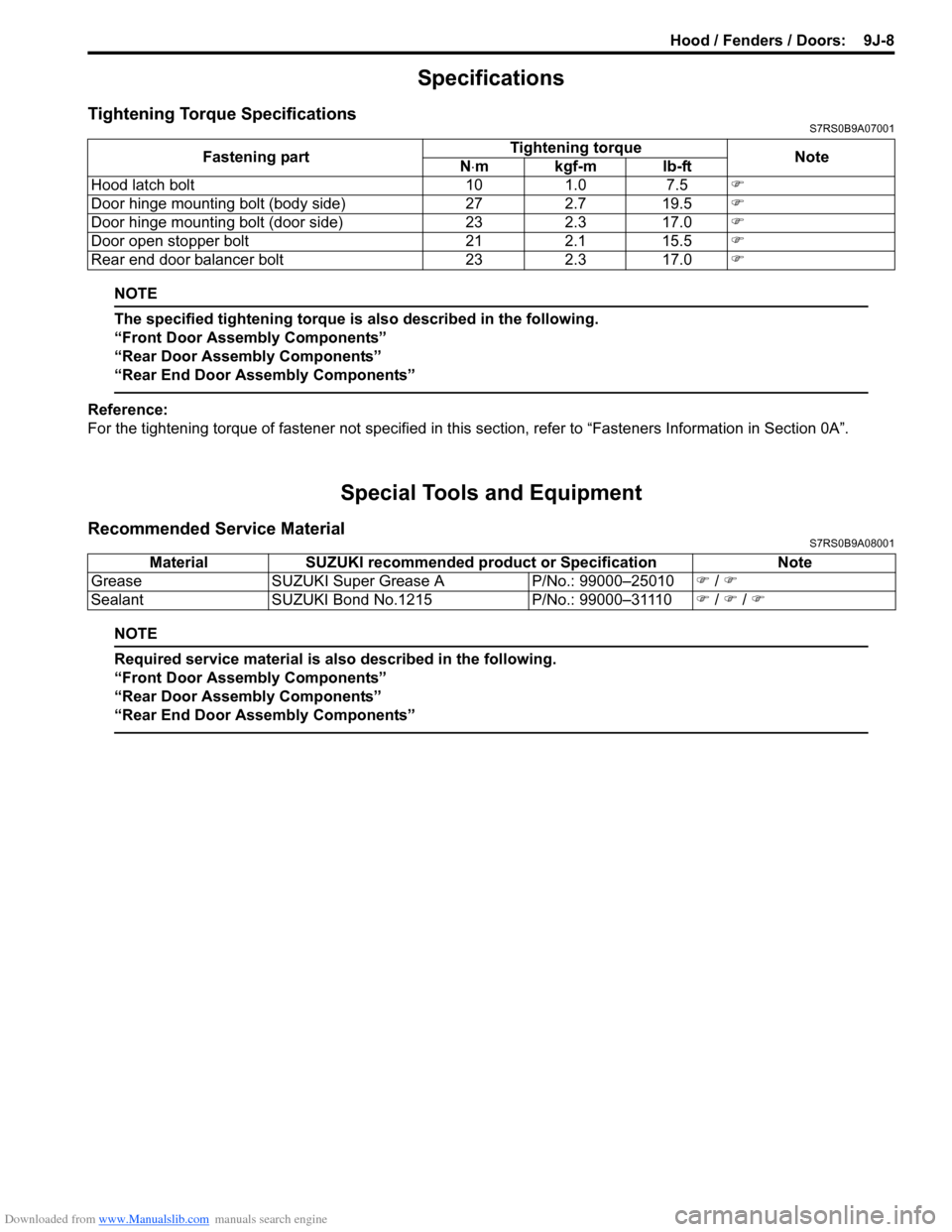
Specifications
Tightening Torque SpecificationsS7RS0B9A07001
NOTE
The specified tightening torque is also described in the following.
“Front Door Assembly Components”
“Rear Door Assembly Components”
“Rear End Door Assembly Components”
Reference:
For the tightening torque of fastener not specified in this section, refer to “Fasteners Information in Section 0A”.
Special Tools and Equipment
Recommended Service MaterialS7RS0B9A08001
NOTE
Required service material is also described in the following.
“Front Door Assembly Components”
“Rear Door Assembly Components”
“Rear End Door Assembly Components”
Fastening part Tightening torque
Note
N ⋅mkgf-mlb-ft
Hood latch bolt 10 1.0 7.5 �)
Door hinge mounting bolt (body side) 27 2.7 19.5 �)
Door hinge mounting bolt (door side) 23 2.3 17.0 �)
Door open stopper bolt 21 2.1 15.5 �)
Rear end door balancer bolt 23 2.3 17.0 �)
MaterialSUZUKI recommended product or Specification Note
Grease SUZUKI Super Grease A P/No.: 99000–25010�) / �)
Sealant SUZUKI Bond No.1215 P/No.: 99000–31110�) / �) / �)
Page 1401 of 1496
Downloaded from www.Manualslib.com manuals search engine Table of Contents 10- i
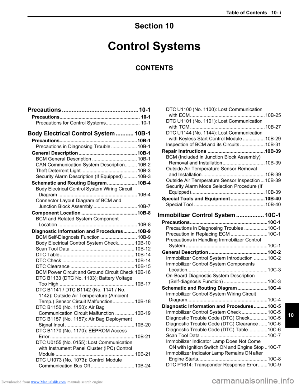
10
Section 10
CONTENTS
Control Systems
Precautions ............................................... 10-1
Precautions........................................................... 10-1
Precautions for Control Systems......................... 10-1
Body Electrical Contro l System ........... 10B-1
Precautions......................................................... 10B-1
Precautions in Diagnosing Trouble ................... 10B-1
General Description ........................................... 10B-1 BCM General Description ................................. 10B-1
CAN Communication System Description......... 10B-2
Theft Deterrent Light ......................................... 10B-3
Security Alarm Description (If Equipped) .......... 10B-3
Schematic and Routing Diagram ...................... 10B-4 Body Electrical Control System Wiring Circuit Diagram .......................................................... 10B-4
Connector Layout Diagram of BCM and Junction Block Assembly ................................ 10B-7
Component Locatio n ......................................... 10B-8
BCM and Related System Component Location .......................................................... 10B-8
Diagnostic Information an d Procedures .......... 10B-9
BCM Self-Diagnosis Function ........................... 10B-9
Body Electrical Control System Check............ 10B-10
Scan Tool Data ............................................... 10B-12
DTC Table ....................................................... 10B-14
DTC Check ..................................................... 10B-14
DTC Clearance ............................................... 10B-15
BCM Power Circuit and Ground Circuit Check 10B-16
DTC B1133 (DTC No. 1133): Battery Voltage Too High ....................................................... 10B-17
DTC B1141 / DTC B1142 (No. 1141 / No. 1142): Outside Air Temperature (Ambient
Temp.) Sensor Circuit Ma lfunction ................ 10B-18
DTC B1150 (No. 1150): Air Bag Communication Circuit Malfunction .............. 10B-19
DTC B1157 (No. 1157): Air Bag Deployment Signal Input ................................................... 10B-20
DTC B1170 (No. 1170 ): EEPROM Access
Error .............................................................. 10B-21
DTC U0155 (No. 0155): Lost Communication with Instrument Panel Cluster (IPC) Control
Module .......................................................... 10B-21
DTC U1073 (No. 1073): Control Module Communication Bus Off ................................ 10B-24 DTC U1100 (No. 1100): Lost Communication
with ECM ....................................................... 10B-25
DTC U1101 (No. 1101): Lost Communication with TCM ....................................................... 10B-27
DTC U1144 (No. 1144): Lost Communication with Keyless Start Control Module ................ 10B-29
Inspection of BCM and its Circuits .................. 10B-31
Repair Instructions ........... ...............................10B-39
BCM (Included in Junction Block Assembly) Removal and Installation ............................... 10B-39
Outside Air Temperature Sensor Removal and Installation .............................................. 10B-39
Outside Air Temperature Sensor Inspection ... 10B-39
Security Alarm Mode Selection Procedure (If Equipped) ...................................................... 10B-39
Special Tools and Equipmen t .........................10B-40
Special Tool .................................................... 10B-40
Immobilizer Control Syst em ................. 10C-1
Precautions.........................................................10C-1
Precautions in Diagnosing Troubles .................10C-1
Precaution in Replacing ECM ...........................10C-1
Precautions in Handli ng Immobilizer Control
System ............................................................10C-1
General Description ...........................................10C-2 Immobilizer Control System Introduction ..........10C-2
Immobilizer Control System Components Location...........................................................10C-3
On-Board Diagnostic System Description (Self-diagnosis Function) ................................10C-3
Schematic and Routing Diag ram ......................10C-4
Immobilizer Control System Wiring Circuit Diagram...........................................................10C-4
Diagnostic Information an d Procedures ..........10C-5
Immobilizer Control System Check ...................10C-5
Diagnostic Trouble Code (DTC) Check.............10C-5
Diagnostic Trouble Code (DTC) Clearance ......10C-6
Diagnostic Trouble Code (DTC) Table ..............10C-6
Scan Tool Data .................................................10C-7
Immobilizer Indicator Lamp Does Not Come ON with Ignition Switch ON and Engine Stop ..10C-7
Immobilizer Indicator Lamp Remains ON after Engine Starts...................................................10C-8
DTC P1614: Transponder Re sponse Error .......10C-9
Page 1402 of 1496
Downloaded from www.Manualslib.com manuals search engine 10-ii Table of Contents
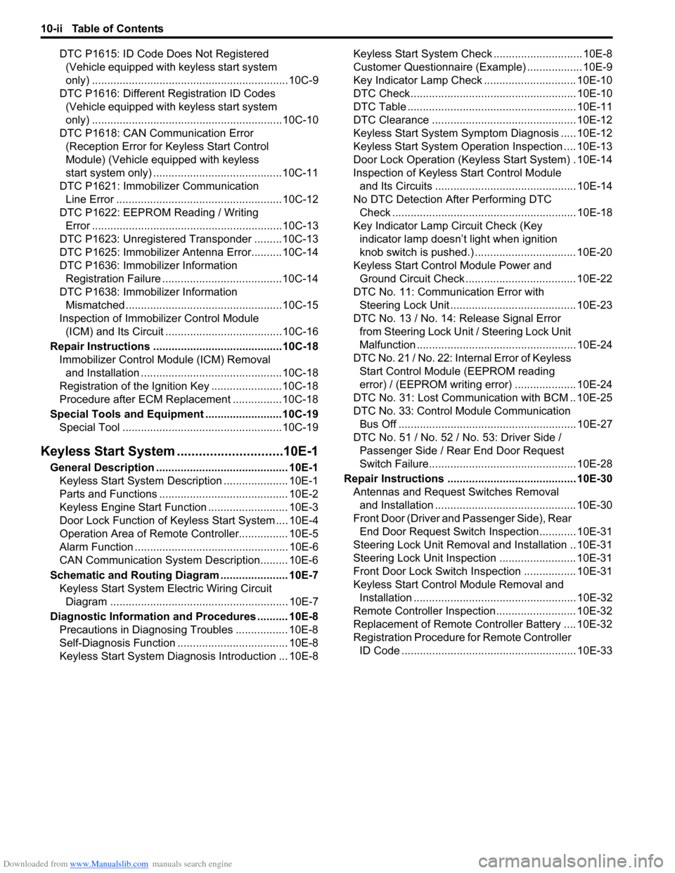
DTC P1615: ID Code Does Not Registered (Vehicle equipped with keyless start system
only) ................................................................10C-9
DTC P1616: Different Registration ID Codes (Vehicle equipped with keyless start system
only) ..............................................................10C-10
DTC P1618: CAN Communication Error (Reception Error for Keyless Start Control
Module) (Vehicle equipped with keyless
start system only) ..........................................10C-11
DTC P1621: Immobilizer Communication Line Error ......................................................10C-12
DTC P1622: EEPROM Reading / Writing Error ..............................................................10C-13
DTC P1623: Unregistered Transponder .........10C-13
DTC P1625: Immobilizer An tenna Error..........10C-14
DTC P1636: Immobilizer Information Registration Failure .......................................10C-14
DTC P1638: Immobilizer Information Mismatched ...................................................10C-15
Inspection of Immobilizer Control Module (ICM) and Its Circuit ....... ...............................10C-16
Repair Instructions ........... ...............................10C-18
Immobilizer Control Mo dule (ICM) Removal
and Installation ..............................................10C-18
Registration of the Ignition Key .......................10C-18
Procedure after ECM Replacement ................10C-18
Special Tools and Equipmen t .........................10C-19
Special Tool ....................................................10C-19
Keyless Start System ....... ......................10E-1
General Description ........................................... 10E-1
Keyless Start System Description ..................... 10E-1
Parts and Functions .......................................... 10E-2
Keyless Engine Start Function .......................... 10E-3
Door Lock Function of Keyless Start System .... 10E-4
Operation Area of Remote Controller................ 10E-5
Alarm Function .................................................. 10E-6
CAN Communication System Description......... 10E-6
Schematic and Routing Diagram ...................... 10E-7 Keyless Start System El ectric Wiring Circuit
Diagram .......................................................... 10E-7
Diagnostic Information and Procedures .......... 10E-8 Precautions in Diagnosing Troubles ................. 10E-8
Self-Diagnosis Function .................................... 10E-8
Keyless Start System Diagn osis Introduction ... 10E-8 Keyless Start System Chec
k ............................. 10E-8
Customer Questionnaire (E xample) .................. 10E-9
Key Indicator Lamp Check .............................. 10E-10
DTC Check...................................................... 10E-10
DTC Table ....................................................... 10E-11
DTC Clearance ............................................... 10E-12
Keyless Start System Symp tom Diagnosis ..... 10E-12
Keyless Start System Operation Inspection .... 10E-13
Door Lock Operation (Keyless Start System) . 10E-14
Inspection of Keyless Start Control Module and Its Circuits .............................................. 10E-14
No DTC Detection After Performing DTC Check ............................................................ 10E-18
Key Indicator Lamp Circuit Check (Key indicator lamp doesn’t light when ignition
knob switch is pushed.) ................................. 10E-20
Keyless Start Control Module Power and Ground Circuit Check .................................... 10E-22
DTC No. 11: Communi cation Error with
Steering Lock Unit ......................................... 10E-23
DTC No. 13 / No. 14: Release Signal Error from Steering Lock Unit / Steering Lock Unit
Malfunction .................................................... 10E-24
DTC No. 21 / No. 22: Internal Error of Keyless Start Control Module (EEPROM reading
error) / (EEPROM writing error) ............ ........ 10E-24
DTC No. 31: Lost Commun ication with BCM .. 10E-25
DTC No. 33: Control Module Communication
Bus Off .......................................................... 10E-27
DTC No. 51 / No. 52 / No. 53: Driver Side / Passenger Side / Rear End Door Request
Switch Failure................................................ 10E-28
Repair Instructions ............ .............................. 10E-30
Antennas and Request Switches Removal and Installation .............................................. 10E-30
Front Door (Driver and Passenger Side), Rear End Door Request Switch Inspection............ 10E-31
Steering Lock Unit Removal and Installation .. 10E-31
Steering Lock Unit Inspection ......................... 10E-31
Front Door Lock Switch In spection ................. 10E-31
Keyless Start Control Module Removal and Installation ..................................................... 10E-32
Remote Controller Inspection.......................... 10E-32
Replacement of Remote Controller Battery .... 10E-32
Registration Procedure for Remote Controller
ID Code ......................................................... 10E-33