Meter SUZUKI SWIFT 2007 2.G Service Workshop Manual
[x] Cancel search | Manufacturer: SUZUKI, Model Year: 2007, Model line: SWIFT, Model: SUZUKI SWIFT 2007 2.GPages: 1496, PDF Size: 34.44 MB
Page 1048 of 1496
Downloaded from www.Manualslib.com manuals search engine 8B-10 Air Bag System:
Diagnostic Information and Procedures
Air Bag Diagnostic System CheckS7RS0B8204001
WARNING!
To avoid deployment when troubleshooting
the air bag system, do not use electrical test
equipment such as a battery powered or AC
powered voltmeter, ohmmeter, etc., or any
type of electrical equipment other than that
specified in this manual. Do not use a non-
powered probe type tester.
Instructions in this manual must be followed
carefully, otherwise personal injury may
result.
CAUTION!
The order in which DTCs are diagnosed is
very important. Failure to diagnose the DTCs
in the order specified may result in extended
diagnostic time, incorrect diagnosis and
incorrect parts replacement.
The diagnostic procedures used are designed to find
and repair air bag system malfunctions.
To get the best results, it is important to use the
diagnostic flow and follow the sequence in the following.1) Perform the “Air Bag Diagnostic System Check Flow”.
(The “Air Bag Diagnostic System Check Flow” must
be the starting point of any air bag system diagnosis.
The “Air Bag Diagnostic System Check Flow” checks
for proper “AIR BAG” warning right operation
through “AIR BAG” warning right and whether air
bag DTCs exist.)
2) Refer to the proper diagnost ic flow as directed by the
“Air Bag Diagnostic System Check Flow”.
(The “Air Bag Diagnostic System Check Flow” will
lead you to the correct flow to diagnose any air bag
system malfunctions. Bypassing these procedures
may result in extended diagnostic time, incorrect
diagnosis and incorrect parts replacement.)
3) Repeat the “Air Bag Diagnostic System Check Flow” after any repair or diagnostic procedures have been
performed.
(Performing the “Air Bag Diagnostic System Check
Flow” after all repair or diagnostic procedures will
ensure that the repair has been made correctly and
that no other malfunctions exist.)
Air Bag Diagnostic System Check FlowS7RS0B8204002
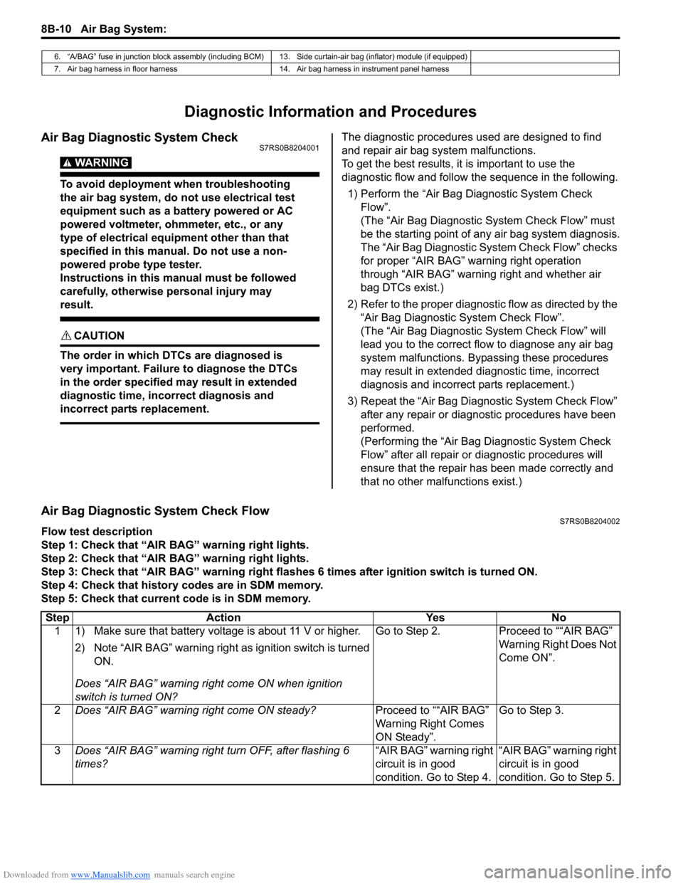
Flow test description
Step 1: Check that “AIR BAG” warning right lights.
Step 2: Check that “AIR BAG” warning right lights.
Step 3: Check that “AIR BAG” warning right flas hes 6 times after ignition switch is turned ON.
Step 4: Check that history codes are in SDM memory.
Step 5: Check that current code is in SDM memory.
6. “A/BAG” fuse in junction block assembly (including BCM) 13. Side curtain-air bag (inflator) module (if equipped)
7. Air bag harness in floor harness 14. Air bag harness in instrument panel harness
Step Action YesNo
1 1) Make sure that battery voltage is about 11 V or higher.
2) Note “AIR BAG” warning right as ignition switch is turned
ON.
Does “AIR BAG” warning ri ght come ON when ignition
switch is turned ON? Go to Step 2.
Proceed to ““AIR BAG”
Warning Right Does Not
Come ON”.
2 Does “AIR BAG” warning right come ON steady? Proceed to ““AIR BAG”
Warning Right Comes
ON Steady”.Go to Step 3.
3 Does “AIR BAG” warning right turn OFF, after flashing 6
times? “AIR BAG” warning right
circuit is in good
condition. Go to Step 4.“AIR BAG” warning right
circuit is in good
condition. Go to Step 5.
Page 1051 of 1496
Downloaded from www.Manualslib.com manuals search engine Air Bag System: 8B-13
Scan Tool DataS7RS0B8204006
Data list of SDM
Definition
Back Up Volt (V)
This parameter indicates the capacity of the backup
condenser installed to maintain the ignition current (as
much as possible) even when the power supply to SDM
that ignites the inflator is shut off.
Battery Voltage (V)
Battery voltage is an analog input signal read by SDM.
System ID (4ch/8ch)
This parameter indicates the number of initiator circuits.
Driv A/B Ini Res (Driver air bag initiator resistance)
(ohm)
This parameter indicates the resistance of the driver air
bag initiator circuit. Pass A/B Ini Res (Passenger air bag initiator
resistance) (ohm)
This parameter indicates the
resistance of the passenger
air bag initiator circuit.
Driv Preten Ini Res (Dri ver pretensioner initiator
resistance) (ohm)
This parameter indicates the resistance of the driver seat
belt pretensioner initiator circuit.
Pass Preten Ini Res (Passenger pretensioner
initiator resistance) (ohm)
This parameter indicates the resistance of the passenger
seat belt pretensioner initiator circuit.
Driv Sidebag Ini Res (Driver side-air bag initiator
resistance) (ohm)
This parameter indicates the resistance of the driver
side-air bag initiator circuit.
Pass Sidebag Ini Res (Passenger side-air bag
initiator resistance) (ohm)
This parameter indicates the resistance of the
Passenger side-air bag initiator circuit.
Driv curtain Ini Res (Driver side curtain-air bag
initiator resistance) (ohm)
This parameter indicates the re sistance of the driver side
curtain-air bag initiator circuit.
Pass curtain Ini Res (Passenger side curtain-air bag
initiator resistance) (ohm)
This parameter indicates the resistance of the passenger
side curtain-air bag initiator circuit.
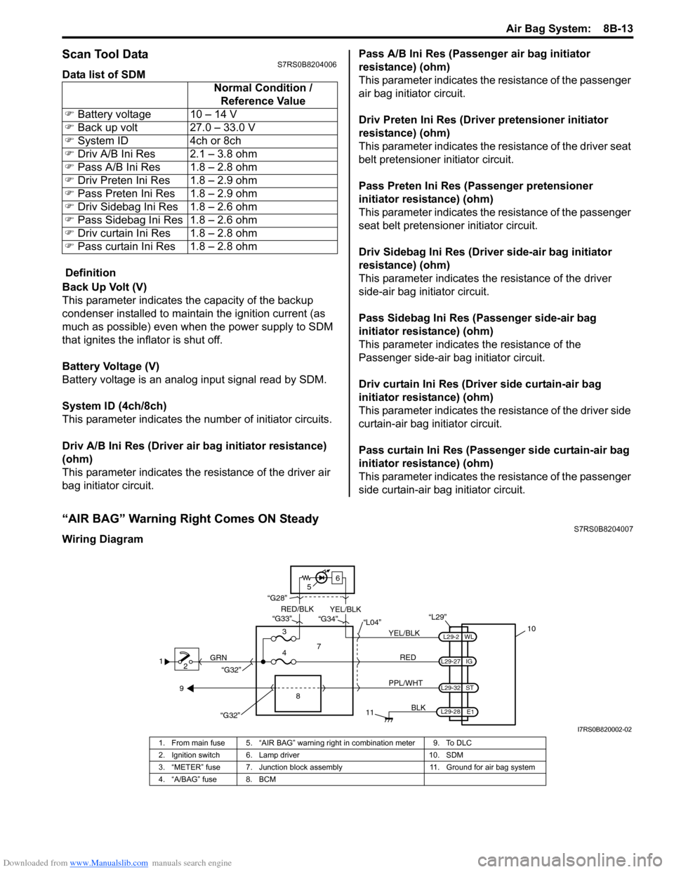
“AIR BAG” Warning Right Comes ON SteadyS7RS0B8204007
Wiring Diagram Normal Condition /
Reference Value
�) Battery voltage 10 – 14 V
�) Back up volt 27.0 – 33.0 V
�) System ID 4ch or 8ch
�) Driv A/B Ini Res 2.1 – 3.8 ohm
�) Pass A/B Ini Res 1.8 – 2.8 ohm
�) Driv Preten Ini Res 1.8 – 2.9 ohm
�) Pass Preten Ini Res 1.8 – 2.9 ohm
�) Driv Sidebag Ini Res 1.8 – 2.6 ohm
�) Pass Sidebag Ini Res 1.8 – 2.6 ohm
�) Driv curtain Ini Res 1.8 – 2.8 ohm
�) Pass curtain Ini Res 1.8 – 2.8 ohm
1
2 GRN
11
BLK
L29-27
L29-2
L29-28 WL
E1
IG
L29-32
ST
10
8
“L29”
RED
PPL/WHT
7
3
4 “L04”
“G34”
“G33”
“G28”
“G32”
5 6
“G32”
YEL/BLK
YEL/BLK
RED/BLK
9
I7RS0B820002-02
1. From main fuse 5. “AIR BAG” warning right in combination meter 9. To DLC
2. Ignition switch 6. Lamp driver 10. SDM
3. “METER” fuse 7. Junction block assembly 11. Ground for air bag system
4. “A/BAG” fuse 8. BCM
Page 1053 of 1496
Downloaded from www.Manualslib.com manuals search engine Air Bag System: 8B-15
NOTE
Upon completion of inspection and repair work, perform the following items.
• Reconnect all air bag system components and ensure all components are properly mounted.
• Repeat “Air Bag Diagnostic System Check” to confirm that the trouble has been corrected.
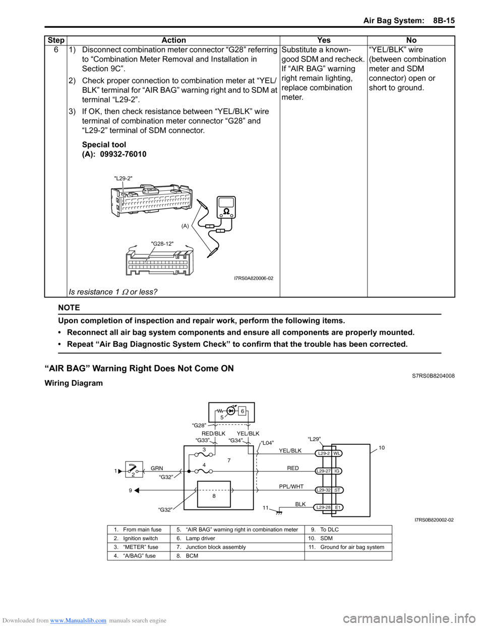
“AIR BAG” Warning Right Does Not Come ONS7RS0B8204008
Wiring Diagram6 1) Disconnect combination meter connector “G28” referring
to “Combination Meter Removal and Installation in
Section 9C”.
2) Check proper connection to combination meter at “YEL/ BLK” terminal for “AIR BAG” warning right and to SDM at
terminal “L29-2”.
3) If OK, then check resistance between “YEL/BLK” wire terminal of combination meter connector “G28” and
“L29-2” terminal of SDM connector.
Special tool
(A): 09932-76010
Is resistance 1
Ω or less? Substitute a known-
good SDM and recheck.
If “AIR BAG” warning
right remain lighting,
replace combination
meter.
“YEL/BLK” wire
(between combination
meter and SDM
connector) open or
short to ground.
Step Action Yes No
"L29-2"
"G28-12"
(A)
I7RS0A820006-02
12 GRN
11
BLK
L29-27
L29-2
L29-28 WL
E1
IG
L29-32
ST
10
8
“L29”
RED
PPL/WHT
7
3
4 “L04”
“G34”
“G33”
“G28”
“G32”
5 6
“G32”
YEL/BLK
YEL/BLK
RED/BLK
9
I7RS0B820002-02
1. From main fuse 5. “AIR BAG” warning right in combination meter 9. To DLC
2. Ignition switch 6. Lamp driver 10. SDM
3. “METER” fuse 7. Junction block assembly 11. Ground for air bag system
4. “A/BAG” fuse 8. BCM
Page 1054 of 1496
Downloaded from www.Manualslib.com manuals search engine 8B-16 Air Bag System:
CAUTION!
• Be sure to perform “Air Bag Diagnostic System Check” before starting diagnosis according to flow.
• When measurement of resistance or voltage is required in this flow, use a tester along with a correct terminal adapter from special tool (Connector test adapter kit).
• When a check for proper connection is required, refer to “Inspection of Intermittent and Poor Connections”.
• If there is open circuit in the air bag wire harnes s, connector or terminal is found damaged, replace
the wire harness, connector and terminal as an assembly.
Flow Test Description
Step 1: Check combination meter power feed circuit.
Step 2: Check “AIR BAG” warning right circuit.
Troubleshooting
NOTE
Upon completion of inspection and repair work, perform the following items.
• Reconnect all air bag system components and ensure all components are properly mounted.
• Repeat “Air Bag Diagnostic System Check” to confirm that the trouble has been corrected.
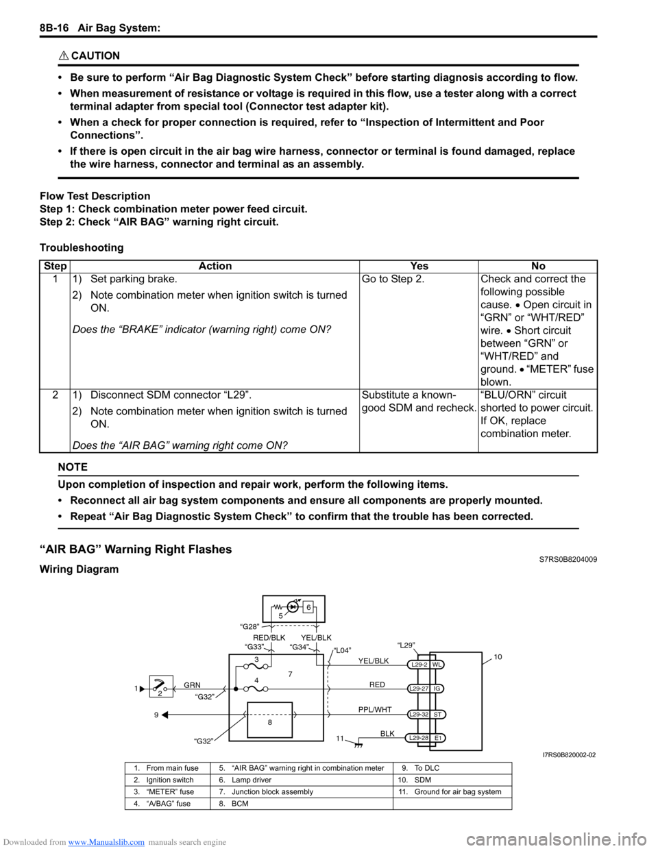
“AIR BAG” Warning Right FlashesS7RS0B8204009
Wiring Diagram Step Action Yes No
1 1) Set parking brake.
2) Note combination me ter when ignition switch is turned
ON.
Does the “BRAKE” in dicator (warning right) come ON? Go to Step 2. Check and correct the
following possible
cause. • Open circuit in
“GRN” or “WHT/RED”
wire. • Short circuit
between “GRN” or
“WHT/RED” and
ground. • “METER” fuse
blown.
2 1) Disconnect SDM connector “L29”.
2) Note combination me ter when ignition switch is turned
ON.
Does the “AIR BAG” warning right come ON? Substitute a known-
good SDM and recheck.
“BLU/ORN” circuit
shorted to power circuit.
If OK, replace
combination meter.
1
2 GRN
11
BLK
L29-27
L29-2
L29-28 WL
E1
IG
L29-32
ST
10
8
“L29”
RED
PPL/WHT
7
3
4 “L04”
“G34”
“G33”
“G28”
“G32”
5 6
“G32”
YEL/BLK
YEL/BLK
RED/BLK
9
I7RS0B820002-02
1. From main fuse 5. “AIR BAG” warning right in combination meter 9. To DLC
2. Ignition switch 6. Lamp driver 10. SDM
3. “METER” fuse 7. Junction block assembly 11. Ground for air bag system
4. “A/BAG” fuse 8. BCM
Page 1055 of 1496
Downloaded from www.Manualslib.com manuals search engine Air Bag System: 8B-17
CAUTION!
• Be sure to perform “Air Bag Diagnostic System Check” before starting diagnosis according to flow.
• When measurement of resistance or voltage is required in this flow, use a tester along with a correct terminal adapter from special tool (Connector test adapter kit).
• When a check for proper connection is required, refer to “Inspection of Intermittent and Poor Connections”.
• If there is open circuit in the air bag wire harnes s, connector or terminal is found damaged, replace
the wire harness, connector and terminal as an assembly.
Flow Test Description
Check for short circuit between diag nosis switch circuit and ground.
Troubleshooting
NOTE
Upon completion of inspection and repair work, perform the following items.
• Reconnect all air bag system components and ensure all components are properly mounted.
• Repeat “Air Bag Diagnostic System Check” to confirm that the trouble has been corrected.
DTC B1013: SDM faultS7RS0B8204010
DTC Will Set when
An internal SDM fault is detected by SDM.
NOTE
DTC B1013 can never be cleared once it has been set.
DTC Troubleshooting 1) Turn ignition switch OFF.
2) Replace SDM.
3) Repeat “Air Bag Diagnostic System Check”.
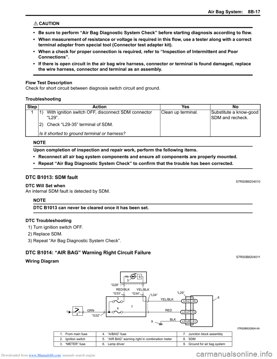
DTC B1014: “AIR BAG” Warning Right Circuit FailureS7RS0B8204011
Wiring DiagramStep Action Yes No
1 1) With ignition switch OFF, disconnect SDM connector “L29”.
2) Check “L29-35” terminal of SDM.
Is it shorted to ground terminal or harness? Clean up terminal. Substitute a know-good
SDM and recheck.
12 GRN
9
BLK
L29-2
L29-27
L29-28 IG
E1
WL
8
“L29”
RED
7
3
4 “L04”
“G34”
“G33”
“G28”
“G32”
5 6
YEL/BLK
YEL/BLK
RED/BLK
I7RS0B820004-04
1. From main fuse 4. “A/BAG” fuse
7. Junction block assembly
2. Ignition switch 5. “AIR BAG” warning right in combination meter 8. SDM
3. “METER” fuse 6. Lamp driver 9. Ground for air bag system
Page 1153 of 1496
Downloaded from www.Manualslib.com manuals search engine Air Bag System: 8B-115
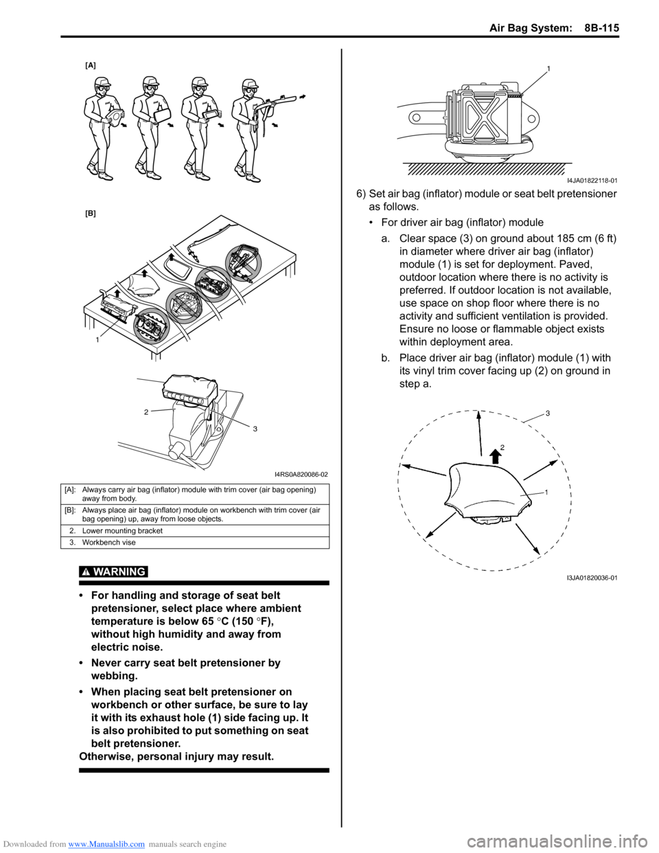
WARNING!
• For handling and storage of seat belt pretensioner, select place where ambient
temperature is below 65 °C (150 °F),
without high humidity and away from
electric noise.
• Never carry seat belt pretensioner by webbing.
• When placing seat belt pretensioner on workbench or other surface, be sure to lay
it with its exhaust hole (1) side facing up. It
is also prohibited to put something on seat
belt pretensioner.
Otherwise, personal injury may result.
6) Set air bag (inflator) module or seat belt pretensioner
as follows.
• For driver air bag (inflator) module
a. Clear space (3) on ground about 185 cm (6 ft) in diameter where driver air bag (inflator)
module (1) is set for deployment. Paved,
outdoor location where there is no activity is
preferred. If outdoor location is not available,
use space on shop floor where there is no
activity and sufficient ventilation is provided.
Ensure no loose or flammable object exists
within deployment area.
b. Place driver air bag (inflator) module (1) with its vinyl trim cover facing up (2) on ground in
step a.
[A]: Always carry air bag (inflator) module with trim cover (air bag opening) away from body.
[B]: Always place air bag (inflator) module on workbench with trim cover (air bag opening) up, away from loose objects.
2. Lower mounting bracket
3. Workbench vise
1
2
3
[A]
[B]
I4RS0A820086-02
1
I4JA01822118-01
I3JA01820036-01
Page 1154 of 1496
Downloaded from www.Manualslib.com manuals search engine 8B-116 Air Bag System:
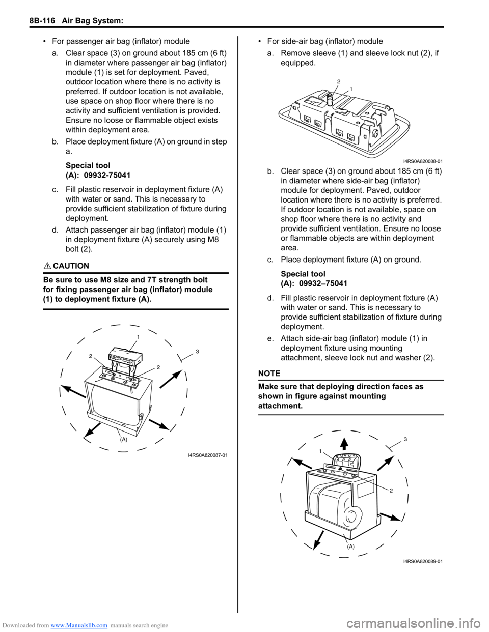
• For passenger air bag (inflator) modulea. Clear space (3) on ground about 185 cm (6 ft) in diameter where passenger air bag (inflator)
module (1) is set for deployment. Paved,
outdoor location where there is no activity is
preferred. If outdoor location is not available,
use space on shop floor where there is no
activity and sufficient ventilation is provided.
Ensure no loose or flammable object exists
within deployment area.
b. Place deployment fixture (A) on ground in step a.
Special tool
(A): 09932-75041
c. Fill plastic reservoir in deployment fixture (A) with water or sand. Th is is necessary to
provide sufficient stabilization of fixture during
deployment.
d. Attach passenger air bag (inflator) module (1) in deployment fixture (A ) securely using M8
bolt (2).
CAUTION!
Be sure to use M8 size and 7T strength bolt
for fixing passenger air bag (inflator) module
(1) to deployment fixture (A).
• For side-air bag (inflator) module
a. Remove sleeve (1) and sl eeve lock nut (2), if
equipped.
b. Clear space (3) on ground about 185 cm (6 ft) in diameter where side-air bag (inflator)
module for deployment. Paved, outdoor
location where there is no activity is preferred.
If outdoor location is not available, space on
shop floor where there is no activity and
provide sufficient ventilation. Ensure no loose
or flammable objects are within deployment
area.
c. Place deployment fixture (A) on ground.
Special tool
(A): 09932–75041
d. Fill plastic reservoir in deployment fixture (A) with water or sand. Th is is necessary to
provide sufficient stabiliz ation of fixture during
deployment.
e. Attach side-air bag (inflator) module (1) in deployment fixture using mounting
attachment, sleeve lock nut and washer (2).
NOTE
Make sure that deploying direction faces as
shown in figure against mounting
attachment.
1
(A)
2
2
3
I4RS0A820087-01
21
I4RS0A820088-01
1
(A) 2
3
I4RS0A820089-01
Page 1155 of 1496
Downloaded from www.Manualslib.com manuals search engine Air Bag System: 8B-117
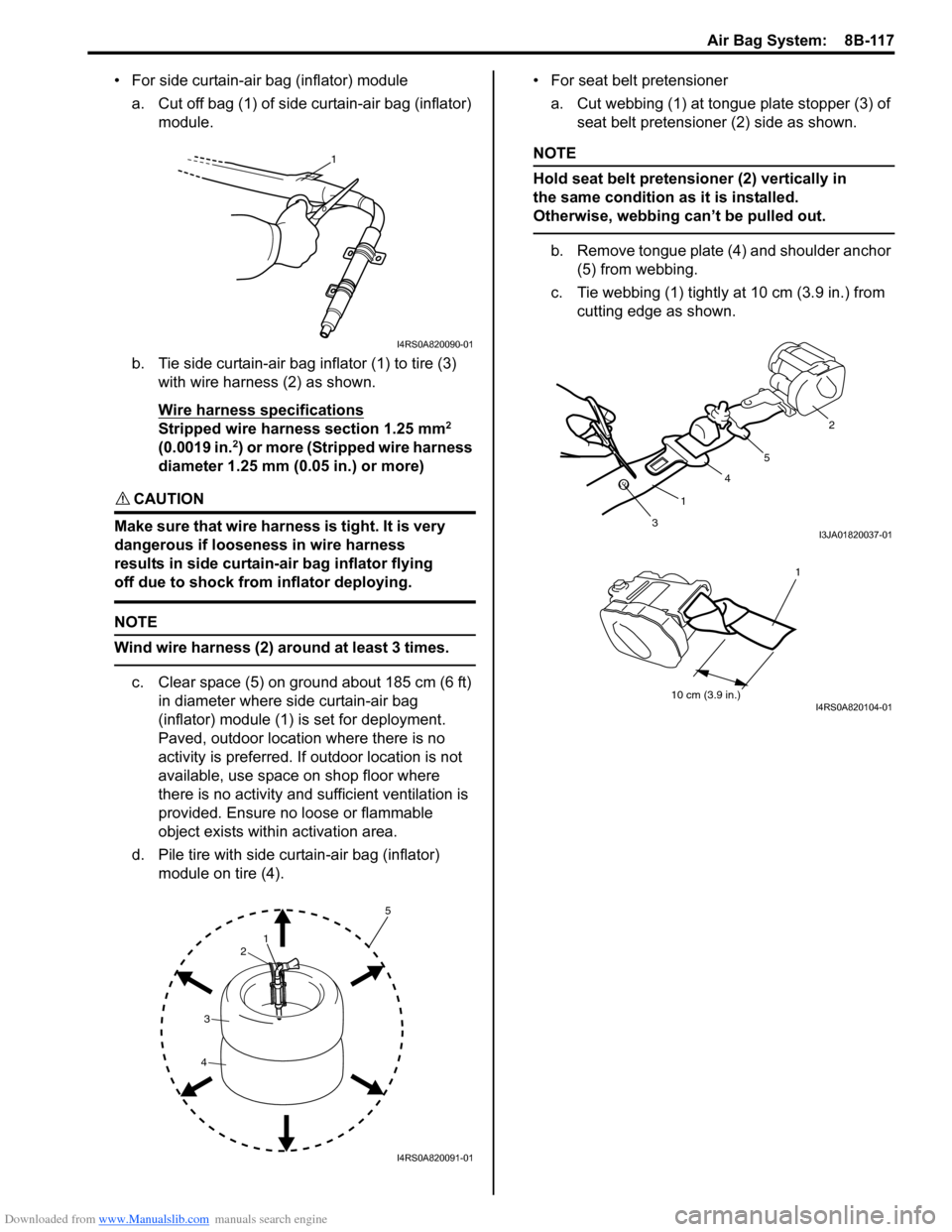
• For side curtain-air bag (inflator) modulea. Cut off bag (1) of side curtain-air bag (inflator) module.
b. Tie side curtain-air bag inflator (1) to tire (3) with wire harness (2) as shown.
Wire harness specifications
Stripped wire harness section 1.25 mm2
(0.0019 in.2) or more (Stripped wire harness
diameter 1.25 mm (0.05 in.) or more)
CAUTION!
Make sure that wire harness is tight. It is very
dangerous if looseness in wire harness
results in side curtain-air bag inflator flying
off due to shock from inflator deploying.
NOTE
Wind wire harness (2) around at least 3 times.
c. Clear space (5) on ground about 185 cm (6 ft) in diameter where side curtain-air bag
(inflator) module (1) is set for deployment.
Paved, outdoor location where there is no
activity is preferred. If outdoor location is not
available, use space on shop floor where
there is no activity and sufficient ventilation is
provided. Ensure no loose or flammable
object exists within activation area.
d. Pile tire with side curtain-air bag (inflator) module on tire (4). • For seat belt pretensioner
a. Cut webbing (1) at tongue plate stopper (3) of seat belt pretensioner (2) side as shown.
NOTE
Hold seat belt pretensioner (2) vertically in
the same condition as it is installed.
Otherwise, webbing can’t be pulled out.
b. Remove tongue plate (4) and shoulder anchor (5) from webbing.
c. Tie webbing (1) tightly at 10 cm (3.9 in.) from
cutting edge as shown.
1
I4RS0A820090-01
1
2
3
4
5
I4RS0A820091-01
3 1 4
5 2I3JA01820037-01
10 cm (3.9 in.)
1
I4RS0A820104-01
Page 1156 of 1496
Downloaded from www.Manualslib.com manuals search engine 8B-118 Air Bag System:
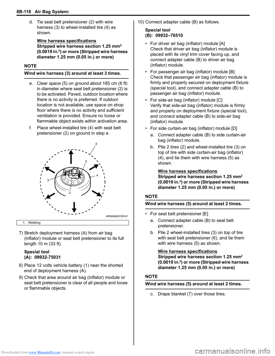
d. Tie seat belt pretensioner (2) with wire harness (3) to wheel-installed tire (4) as
shown.
Wire harness specifications
Stripped wire harness section 1.25 mm2
(0.0019 in.2) or more (Stripped wire harness
diameter 1.25 mm (0.05 in.) or more)
NOTE
Wind wire harness (3) around at least 3 times.
e. Clear space (5) on ground about 185 cm (6 ft) in diameter where seat belt pretensioner (2) is
to be activated. Paved, outdoor location where
there is no activity is preferred. If outdoor
location is not available, use space on shop
floor where there is no activity and sufficient
ventilation is provided. Ensure no loose or
flammable object exists within activation area.
f. Place wheel-installed tire (4) with seat belt pretensioner (2) on ground in step e.
7) Stretch deployment harness (A) from air bag (inflator) module or seat belt pretensioner to its full
length 10 m (33 ft).
Special tool
(A): 09932-75031
8) Place 12 volts vehicle battery (1) near the shorted end of deployment harness (A).
9) Check that area around air bag (inflator) module or seat belt pretensioner is clear of all people and loose
or flammable objects. 10) Connect adapter cable (B) as follows.
Special tool
(B): 09932–76510
• For driver air bag (inflator) module [A]Check that driver air bag (inflator) module is
placed with its vinyl trim cover facing up, and
connect adapter cable (B) to driver air bag
(inflator) module.
• For passenger air bag (inflator) module [B] Check that passenger air bag (inflator) module is
firmly and properly secured on deployment fixture
(special tool), and connect adapter cable (B) to
passenger air bag (inflator) module.
• For side-air bag (inflator) module [C] Verify that side-air bag (inflator) module is firmly
and properly on deployment fixture (special tool),
and connect adapter cable (B) to side-air bag
(inflator) module.
• For side curtain-air bag (inflator) module [D] a. Connect adapter cable (B) to side curtain-air bag (inflator) module.
b. Pile 2 tires (2) and wheel-installed tire (3) on top of tire with side curtain-air bag (inflator)
(4), and tie them with wire harness (5) as
shown.
Wire harness specifications
Stripped wire harness section 1.25 mm2
(0.0019 in.2) or more (Stripped wire harness
diameter 1.25 mm (0.05 in.) or more)
NOTE
Wind wire harness (5) around at least 2 times.
• For seat belt pretensioner [E]
a. Connect adapter cable (B) to seat belt pretensioner.
b. Pile 2 wheel-installed tires (3) on top of tire with seat belt pretensioner (6), and tie them
with wire harness (5) as shown.
Wire harness specifications
Stripped wire harness section 1.25 mm2
(0.0019 in.2) or more (Stripped wire harness
diameter 1.25 mm (0.05 in.) or more)
NOTE
Wind wire harness (5) around at least 2 times.
c. Drape blanket (7) over those tires.
1. Webbing
4
3
3 2 5
I4RS0A820105-01
Page 1163 of 1496
Downloaded from www.Manualslib.com manuals search engine Air Bag System: 8B-125
Specifications
Tightening Torque SpecificationsS7RS0B8207001
NOTE
The specified tightening torque is also described in the following.
“Air Bag System Components, Wiring and Connectors Location”
Reference:
For the tightening torque of fastener not specified in this section, refer to “Fasteners Information in Section 0A”.
Special Tools and Equipment
Use of Special ToolsS7RS0B8208001
WARNING!
To avoid deployment when troubleshooting
the air bag system, do not use electrical test
equipment such as a battery powered or AC
powered voltmeter, ohmmeter, etc., or any
type of electrical equipment other than that
specified. Do not use a non-powered probe
type tester.
Instructions must be followed carefully,
otherwise personal injury may result.
You should be familiar with the tools listed under the
heading “Special Tool”. You should be able to measure
voltage and resistance. You should be familiar with
proper use of a scan tool such as Air Bag Driver /
Passenger Load Tool, Connector Test Adapter Kit and
the Digital Multimeter.
Special tool
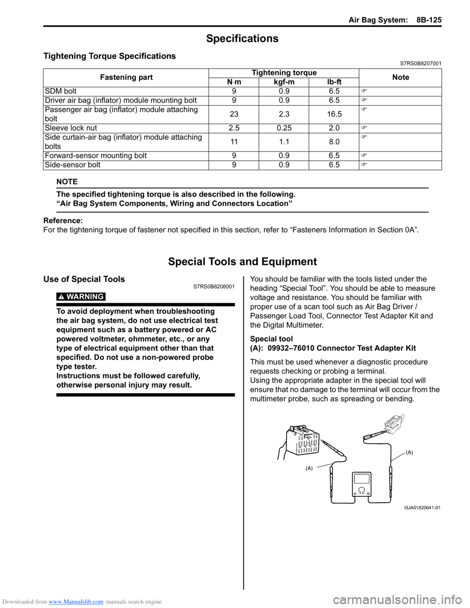
(A): 09932–76010 Connector Test Adapter Kit
This must be used whenever a diagnostic procedure
requests checking or probing a terminal.
Using the appropriate adapter in the special tool will
ensure that no damage to the terminal will occur from the
multimeter probe, such as spreading or bending.
Fastening part
Tightening torque
Note
N ⋅mkgf-mlb-ft
SDM bolt 9 0.9 6.5 �)
Driver air bag (inflator) module mounting bolt 9 0.9 6.5 �)
Passenger air bag (inflator) module attaching
bolt 23 2.3 16.5�)
Sleeve lock nut 2.5 0.25 2.0 �)
Side curtain-air bag (inflator) module attaching
bolts 11 1.1 8.0�)
Forward-sensor mounting bolt 9 0.9 6.5 �)
Side-sensor bolt 9 0.9 6.5 �)
I3JA01820041-01