0b -10 SUZUKI SWIFT 2007 2.G Service User Guide
[x] Cancel search | Manufacturer: SUZUKI, Model Year: 2007, Model line: SWIFT, Model: SUZUKI SWIFT 2007 2.GPages: 1496, PDF Size: 34.44 MB
Page 60 of 1496
Downloaded from www.Manualslib.com manuals search engine 1A-10 Engine General Information and Diagnosis:
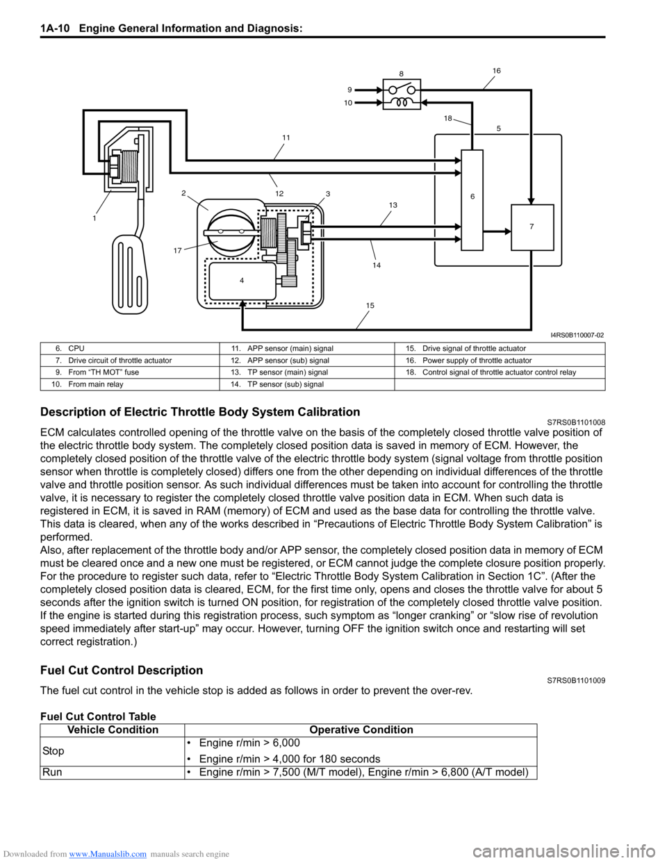
Description of Electric Throttle Body System CalibrationS7RS0B1101008
ECM calculates controlled opening of the throttle valve on the basis of the completely closed throttle valve position of
the electric throttle body system. The completely closed position data is saved in memory of ECM. However, the
completely closed position of the throttle valve of the electric throttle body system (signal voltage from throttle position
sensor when throttle is completely closed) differs one from the other depending on individual differences of the throttle
valve and throttle position sensor. As such individual diff erences must be taken into account for controlling the throttle
valve, it is necessary to register the completely closed throttle valve position data in ECM. When such data is
registered in ECM, it is sa ved in RAM (memory) of ECM and used as the base data for controlling the throttle valve.
This data is cleared, when any of the works described in “Preca utions of Electric Throttle Body System Calibration” is
performed.
Also, after replacement of the throttle body and/or APP sensor , the completely closed position data in memory of ECM
must be cleared once and a new one must be registered, or ECM cannot judge the complete closure position properly.
For the procedure to register such data, refer to “Electric Throttle Body System Calibration in Section 1C”. (After the
completely closed position data is cleared , ECM, for the first time only, opens and closes the throttle valve for about 5
seconds after the ignition switch is turned ON position, for re gistration of the completely closed throttle valve position.
If the engine is started during this registration process, such symptom as “longe r cranking” or “slow rise of revolution
speed immediately after start-up” may occur. However, turning OFF the ignition switch once and restarting will set
correct registration.)
Fuel Cut Control DescriptionS7RS0B1101009
The fuel cut control in the vehicle stop is add ed as follows in order to prevent the over-rev.
Fuel Cut Control Table
4
1
2
17 3 5
6 7
8
9
10
11
12 13
14
15 16
18
I4RS0B110007-02
6. CPU 11. APP sensor (main) signal15. Drive signal of throttle actuator
7. Drive circuit of throttle actuator 12. APP sensor (sub) signal 16. Power supply of throttle actuator
9. From “TH MOT” fuse 13. TP sensor (main) signal 18. Control signal of throttle actuator control relay
10. From main relay 14. TP sensor (sub) signal
Vehicle ConditionOperative Condition
Sto p • Engine r/min > 6,000
• Engine r/min > 4,000 for 180 seconds
Run • Engine r/min > 7,500 (M/T model), Engine r/min > 6,800 (A/T model)
Page 64 of 1496
Downloaded from www.Manualslib.com manuals search engine 1A-14 Engine General Information and Diagnosis:
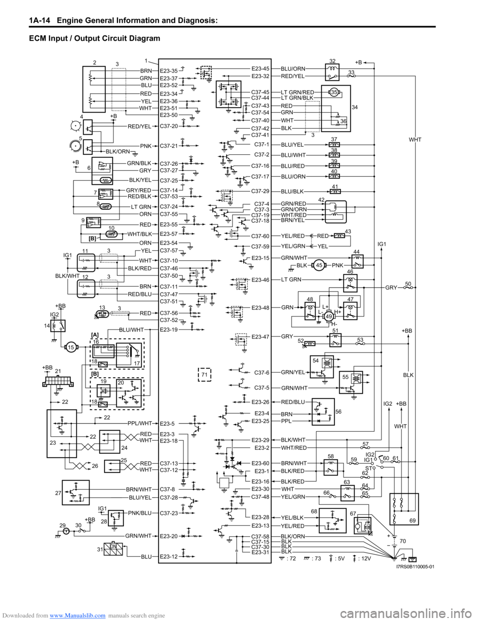
ECM Input / Output Circuit Diagram
+B
58
IG1 +BB
ST IG2 IG2
60 61
69
BLK/WHT
WHT/RED
BRN/WHTBLK/RED
67
: 72: 73: 5V: 12V 70
59 IG1
YEL/BLK
YEL/GRN
YEL/RED
WHT
BLK/ORN
BLK
BLK
57
62
64
65
63
66
68
5 +B
4PNKBLK/ORN
RED/YEL
7
6GRY/REDRED/BLK
LT GRN
GRY
ORN
+B
BLK/YEL
GRN/BLK
10
ORN
WHT/BLK
9
8
RED
IG1
11
12WHT
BRNRED/BLU
3 3
YEL
BLK/REDBLK/WHT 1
37
38
39
40BLU/YEL
BLU/WHT
BLU/RED
BLU/ORN
42
BRN/YELWHT/RED
GRN/REDGRN/ORN
BLK/RED
BLK
E23-30E23-16
E23-60
E23-1
E23-2E23-29
BLK
WHT
+
+BB
WHT
41BLU/BLK
BRN
2
3
BLU
REDYELWHT
GRN
BLK
LT GRN/BLK
36
34
35
32
WHT
GRNRED
BLU/ORN
LT GRN/RED
RED/YEL
[B]
C37-30E23-31
E23-28
E23-13
C37-58
C37-48
C37-15
GRN/YEL
54
55
GRN/WHTC37-5
C37-6
51
52GRY53E23-47 44
45PNKBLKGRN/WHTE23-15
YEL/RED
YEL/GRN
43YEL
RED
C37-59
C37-60
C37-18C37-19
C37-29
46
47
48
L+
H+
L-
H-
49
LT GRN
GRN
50GRYE23-46
E23-48
C37-4C37-3
C37-17
C37-16
C37-2
C37-1
C37-41C37-42
C37-40
C37-54C37-43
C37-44C37-45
E23-45E23-32E23-35E23-37E23-52
E23-51E23-50
C37-20
C37-21
C37-26C37-27
E23-34E23-36
C37-25
C37-14C37-53
C37-24C37-55
E23-55
E23-57
C37-10
C37-11
C37-5113RED3C37-56C37-52
C37-46
C37-47
C37-57E23-54
C37-50
30
+BB
GRN/WHT
29E23-20
31
DN
BLUE23-12
IG1PNK/BLU
28
C37-23
BLU/YEL27C37-8
C37-28
BRN/WHT
BRNPPL
56
E23-25E23-4
RED/BLUE23-26
71
[A]
16
18
19
18 22
23 22
24
25
21
20
[B] 17
14
IG2
+BB
+BB
REDWHT
BLU/WHT
PPL/WHT
15
REDWHT26
E23-19
E23-5
E23-3E23-18
C37-13C37-12
22
33
3
I7RS0B110005-01
Page 104 of 1496
Downloaded from www.Manualslib.com manuals search engine 1A-54 Engine General Information and Diagnosis:
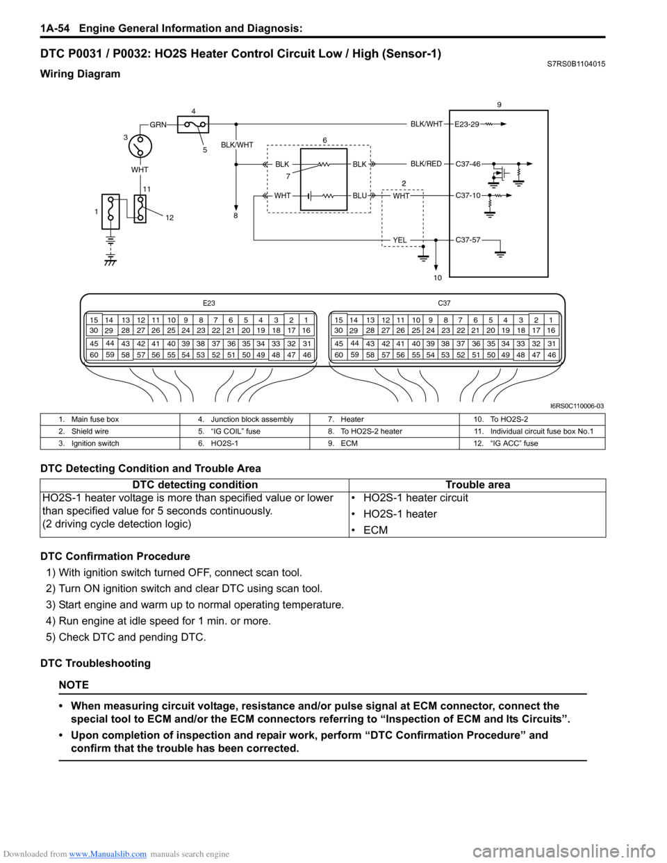
DTC P0031 / P0032: HO2S Heater Control Circuit Low / High (Sensor-1)S7RS0B1104015
Wiring Diagram
DTC Detecting Condition and Trouble Area
DTC Confirmation Procedure1) With ignition switch turned OFF, connect scan tool.
2) Turn ON ignition switch and clear DTC using scan tool.
3) Start engine and warm up to normal operating temperature.
4) Run engine at idle speed for 1 min. or more.
5) Check DTC and pending DTC.
DTC Troubleshooting
NOTE
• When measuring circuit voltage, resistance and/ or pulse signal at ECM connector, connect the
special tool to ECM and/or the ECM connectors re ferring to “Inspection of ECM and Its Circuits”.
• Upon completion of inspection and repair work, perform “DTC Confirmation Procedure” and confirm that the trouble has been corrected.
E23 C37
34
1819
567
1011
17
20
47 46
495051
2122
52 16
25 9
24
14
29
55
57 54 53
59
60 58 2
262728
15
30
56 4832 31
34353637
40
42 39 38
44
45 43 41 331
1213
238
34
1819
567
1011
17
20
47 46
495051
2122
52 16
25 9
24
14
29
55
57 54 53
59
60 58 2
262728
15
30
56 4832 31
34353637
40
42 39 38
44
45 43 41 331
1213
238
BLK/WHT
WHT
11
GRN
3 9
E23-29
WHT
YEL
BLK/WHT
BLKC37-46
C37-10
C37-57
6
7
10
BLK
BLUWHT
BLK/RED
4
5
8
12
1
I6RS0C110006-03
1. Main fuse box
4. Junction block assembly 7. Heater 10. To HO2S-2
2. Shield wire 5. “IG COIL” fuse8. To HO2S-2 heater 11. Individual circuit fuse box No.1
3. Ignition switch 6. HO2S-19. ECM 12. “IG ACC” fuse
DTC detecting condition Trouble area
HO2S-1 heater voltage is more than specified value or lower
than specified value for 5 seconds continuously.
(2 driving cycle detection logic) • HO2S-1 heater circuit
• HO2S-1 heater
•ECM
Page 138 of 1496
Downloaded from www.Manualslib.com manuals search engine 1A-88 Engine General Information and Diagnosis:
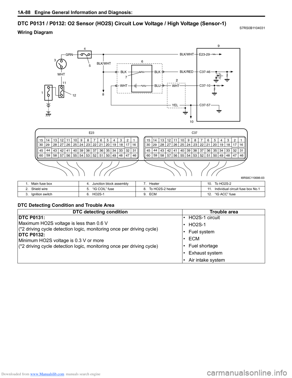
DTC P0131 / P0132: O2 Sensor (HO2S) Circuit Low Voltage / High Voltage (Sensor-1)S7RS0B1104031
Wiring Diagram
DTC Detecting Condition and Trouble Area
E23C37
34
1819
567
1011
17
20
47 46
495051
2122
52 16
25 9
24
14
29
55
57 54 53
59
60 58 2
262728
15
30
56 4832 31
34353637
40
42 39 38
44
45 43 41 331
1213
238
34
1819
567
1011
17
20
47 46
495051
2122
52 16
25 9
24
14
29
55
57 54 53
59
60 58 2
262728
15
30
56 4832 31
34353637
40
42 39 38
44
45 43 41 331
1213
238
BLK/WHT
WHT
11
GRN
3 9
E23-29
WHT
YEL
BLK/WHT
BLKC37-46
C37-10
C37-57
6
7
10
BLK
BLUWHT
BLK/RED
4
5
8
12
1
I6RS0C110006-03
1. Main fuse box
4. Junction block assembly 7. Heater 10. To HO2S-2
2. Shield wire 5. “IG COIL” fuse8. To HO2S-2 heater 11. Individual circuit fuse box No.1
3. Ignition switch 6. HO2S-19. ECM 12. “IG ACC” fuse
DTC detecting condition Trouble area
DTC P0131:
Maximum HO2S voltage is less than 0.6 V
(*2 driving cycle detection logic, monitoring once per driving cycle)
DTC P0132:
Minimum HO2S voltage is 0.3 V or more
(*2 driving cycle detection logic, monitoring once per driving cycle) • HO2S-1 circuit
•HO2S-1
• Fuel system
•ECM
• Fuel shortage
• Exhaust system
• Air intake system
Page 140 of 1496
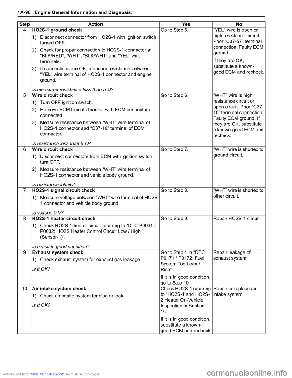
Downloaded from www.Manualslib.com manuals search engine 1A-90 Engine General Information and Diagnosis:
4HO2S-1 ground check
1) Disconnect connector from HO 2S-1 with ignition switch
turned OFF.
2) Check for proper connection to HO2S-1 connector at “BLK/RED”, “WHT”, “BLK /WHT” and “YEL” wire
terminals.
3) If connections are OK, m easure resistance between
“YEL” wire terminal of HO2S-1 connector and engine
ground.
Is measured resistance less than 5
Ω? Go to Step 5. “YEL” wire is open or
high resistance circuit.
Poor “C37-57” terminal
connection. Faulty ECM
ground.
If they are OK,
substitute a known-
good ECM and recheck.
5 Wire circuit check
1) Turn OFF ignition switch.
2) Remove ECM from its br acket with ECM connectors
connected.
3) Measure resistance between “WHT” wire terminal of HO2S-1 connector and “C37-10” terminal of ECM
connector.
Is resistance less than 5
Ω? Go to Step 6. “WHT” wire is high
resistance circuit or
open circuit. Poor “C37-
10” terminal connection.
Faulty ECM ground. If
they are OK, substitute
a known-good ECM and
recheck.
6 Wire circuit check
1) Disconnect connectors from ECM with ignition switch
turn OFF.
2) Measure resistance between “WHT” wire terminal of HO2S-1 connector and vehicle body ground.
Is resistance infinity? Go to Step 7. “WHT” wire is shorted to
ground circuit.
7 HO2S-1 signal circuit check
1) Measure voltage between “WHT” wire terminal of HO2S-
1 connector and vehicle body ground.
Is voltage 0 V? Go to Step 8. “WHT” wire is shorted to
other circuit.
8 HO2S-1 heater circuit check
1) Check HO2S-1 heater circuit referring to “DTC P0031 /
P0032: HO2S Heater Control Circuit Low / High
(Sensor-1)”.
Is circuit in good condition? Go to Step 9. Repair HO2S-1 circuit.
9 Exhaust system check
1) Check exhaust system for exhaust gas leakage.
Is it OK? Go to Step 4 in “DTC
P0171 / P0172: Fuel
System Too Lean /
Rich”.
If it is in good condition,
go to Step 10.Repair leakage of
exhaust system.
10 Air intake system check
1) Check air intake system for clog or leak.
Is it OK? Check HO2S-1 referring
to “HO2S-1 and HO2S-
2 Heater On-Vehicle
Inspection in Section
1C”.
If it is in good condition,
substitute a known-
good ECM and recheck.Repair or replace air
intake system.
Step Action Yes No
Page 143 of 1496
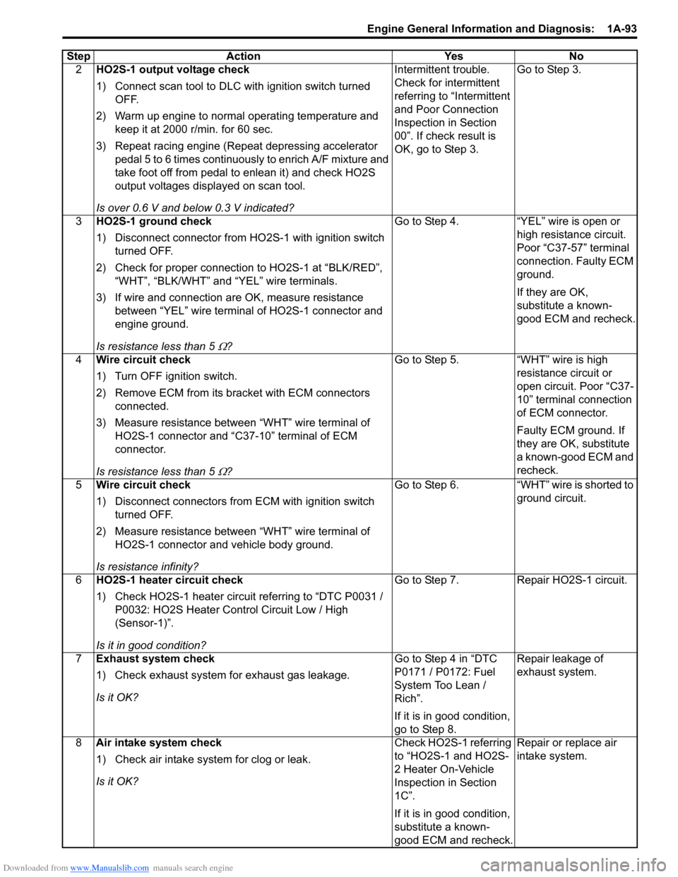
Downloaded from www.Manualslib.com manuals search engine Engine General Information and Diagnosis: 1A-93
2HO2S-1 output voltage check
1) Connect scan tool to DLC with ignition switch turned
OFF.
2) Warm up engine to normal operating temperature and keep it at 2000 r/min. for 60 sec.
3) Repeat racing engine (Repeat depressing accelerator pedal 5 to 6 times continuous ly to enrich A/F mixture and
take foot off from pedal to enlean it) and check HO2S
output voltages displayed on scan tool.
Is over 0.6 V and below 0.3 V indicated? Intermittent trouble.
Check for intermittent
referring to “Intermittent
and Poor Connection
Inspection in Section
00”. If check result is
OK, go to Step 3.
Go to Step 3.
3 HO2S-1 ground check
1) Disconnect connector from HO 2S-1 with ignition switch
turned OFF.
2) Check for proper connection to HO2S-1 at “BLK/RED”, “WHT”, “BLK/WHT” and “YEL” wire terminals.
3) If wire and connection are OK, measure resistance between “YEL” wire terminal of HO2S-1 connector and
engine ground.
Is resistance less than 5
Ω? Go to Step 4. “YEL” wire is open or
high resistance circuit.
Poor “C37-57” terminal
connection. Faulty ECM
ground.
If they are OK,
substitute a known-
good ECM and recheck.
4 Wire circuit check
1) Turn OFF ignition switch.
2) Remove ECM from its br acket with ECM connectors
connected.
3) Measure resistance between “WHT” wire terminal of HO2S-1 connector and “C37-10” terminal of ECM
connector.
Is resistance less than 5
Ω? Go to Step 5. “WHT” wire is high
resistance circuit or
open circuit. Poor “C37-
10” terminal connection
of ECM connector.
Faulty ECM ground. If
they are OK, substitute
a known-good ECM and
recheck.
5 Wire circuit check
1) Disconnect connectors from ECM with ignition switch
turned OFF.
2) Measure resistance between “WHT” wire terminal of HO2S-1 connector and vehicle body ground.
Is resistance infinity? Go to Step 6. “WHT” wire is shorted to
ground circuit.
6 HO2S-1 heater circuit check
1) Check HO2S-1 heater circuit referring to “DTC P0031 /
P0032: HO2S Heater Control Circuit Low / High
(Sensor-1)”.
Is it in good condition? Go to Step 7. Repair HO2S-1 circuit.
7 Exhaust system check
1) Check exhaust system for exhaust gas leakage.
Is it OK? Go to Step 4 in “DTC
P0171 / P0172: Fuel
System Too Lean /
Rich”.
If it is in good condition,
go to Step 8.Repair leakage of
exhaust system.
8 Air intake system check
1) Check air intake system for clog or leak.
Is it OK? Check HO2S-1 referring
to “HO2S-1 and HO2S-
2 Heater On-Vehicle
Inspection in Section
1C”.
If it is in good condition,
substitute a known-
good ECM and recheck.Repair or replace air
intake system.
Step Action Yes No
Page 150 of 1496
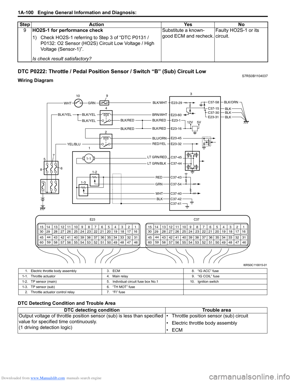
Downloaded from www.Manualslib.com manuals search engine 1A-100 Engine General Information and Diagnosis:
DTC P0222: Throttle / Pedal Position Sensor / Switch “B” (Sub) Circuit LowS7RS0B1104037
Wiring Diagram
DTC Detecting Condition and Trouble Area9
HO2S-1 for performance check
1) Check HO2S-1 referring to Step 3 of “DTC P0131 /
P0132: O2 Sensor (HO2S) Circuit Low Voltage / High
Voltage (Sensor-1)”.
Is check result satisfactory? Substitute a known-
good ECM and recheck.
Faulty HO2S-1 or its
circuit.
Step Action Yes No
E23
C37
34
1819
567
1011
17
20
47 46
495051
2122
52 16
25 9
24
14
29
55
57 54 53
59
60 58 2
262728
15
30
56 4832 31
34353637
40
42 39 38
44
45 43 41 331
1213
238
34
1819
567
1011
17
20
47 46
495051
2122
52 16
25 9
24
14
29
55
57 54 53
59
60 58 2
262728
15
30
56 4832 31
34353637
40
42 39 38
44
45 43 41 331
1213
238
12V
5VBLK/REDBLK/RED
BLK/YEL
12BLK/YEL
BLK/YEL
BRN/WHT
E23-1
E23-60
C37-58
C37-15 C37-30
BLK/ORN
BLKBLKE23-31 BLK
BLK/RED
BLU/ORN
RED/YELYEL/BLU
LT GRN/RED
LT GRN/BLK
RED
GRN
WHT
BLK
E23-16
E23-45
E23-32
C37-45
C37-44
C37-41C37-42
C37-40
C37-54
C37-43
1-1
1-2
1-3 3
4
5
8 67
10
9
E23-29 GRNBLK/WHTWHT
BLK/RED
I6RS0C110015-01
1. Electric throttle body assembly
3. ECM 8. “IG ACC” fuse
1-1. Throttle actuator 4. Main relay 9. “IG COIL” fuse
1-2. TP sensor (main) 5. Individual circuit fuse box No.110. Ignition switch
1-3. TP sensor (sub) 6. “TH MOT” fuse
2. Throttle actuator control relay 7. “FI” fuse
DTC detecting condition Trouble area
Output voltage of throttle position sensor (sub) is less than specified
value for specified time continuously.
(1 driving detection logic) • Throttle position sensor (sub) circuit
• Electric throttle body assembly
•ECM
Page 151 of 1496
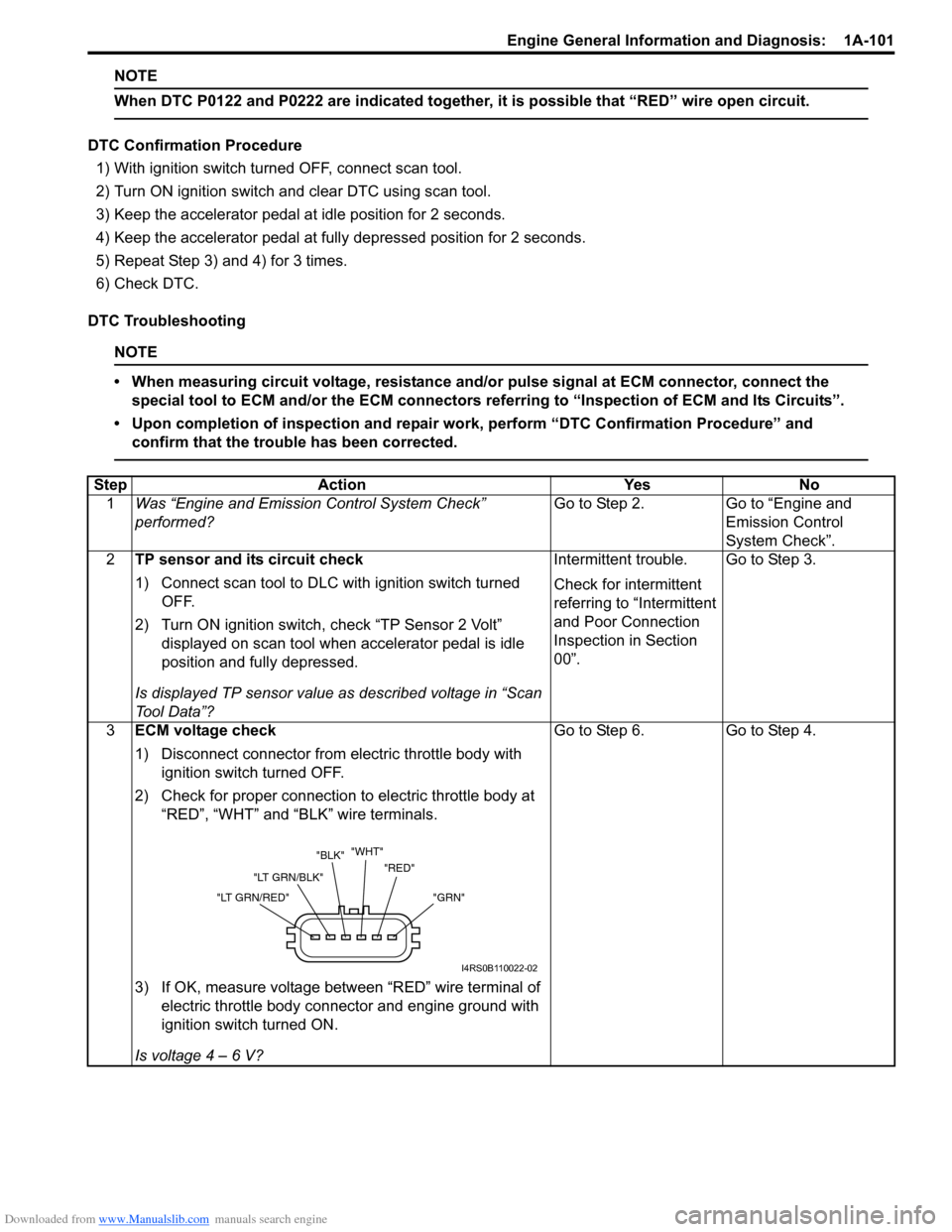
Downloaded from www.Manualslib.com manuals search engine Engine General Information and Diagnosis: 1A-101
NOTE
When DTC P0122 and P0222 are indicated together, it is possible that “RED” wire open circuit.
DTC Confirmation Procedure
1) With ignition switch turned OFF, connect scan tool.
2) Turn ON ignition switch and clear DTC using scan tool.
3) Keep the accelerator pedal at idle position for 2 seconds.
4) Keep the accelerator pedal at fully depressed position for 2 seconds.
5) Repeat Step 3) and 4) for 3 times.
6) Check DTC.
DTC Troubleshooting
NOTE
• When measuring circuit voltage, resistance and/ or pulse signal at ECM connector, connect the
special tool to ECM and/or the ECM connectors re ferring to “Inspection of ECM and Its Circuits”.
• Upon completion of inspection and repair work, perform “DTC Confirmation Procedure” and confirm that the trouble has been corrected.
Step Action YesNo
1 Was “Engine and Emission Control System Check”
performed? Go to Step 2.
Go to “Engine and
Emission Control
System Check”.
2 TP sensor and its circuit check
1) Connect scan tool to DLC with ignition switch turned
OFF.
2) Turn ON ignition switch, check “TP Sensor 2 Volt” displayed on scan tool when accelerator pedal is idle
position and fully depressed.
Is displayed TP sensor value as described voltage in “Scan
To o l D a t a ” ? Intermittent trouble.
Check for intermittent
referring to “Intermittent
and Poor Connection
Inspection in Section
00”.
Go to Step 3.
3 ECM voltage check
1) Disconnect connector from electric throttle body with
ignition switch turned OFF.
2) Check for proper connection to electric throttle body at “RED”, “WHT” and “BLK” wire terminals.
3) If OK, measure voltage between “RED” wire terminal of electric throttle body connector and engine ground with
ignition switch turned ON.
Is voltage 4 – 6 V? Go to Step 6.
Go to Step 4.
"GRN"
"RED"
"WHT"
"BLK"
"LT GRN/BLK"
"LT GRN/RED"
I4RS0B110022-02
Page 152 of 1496
Downloaded from www.Manualslib.com manuals search engine 1A-102 Engine General Information and Diagnosis:
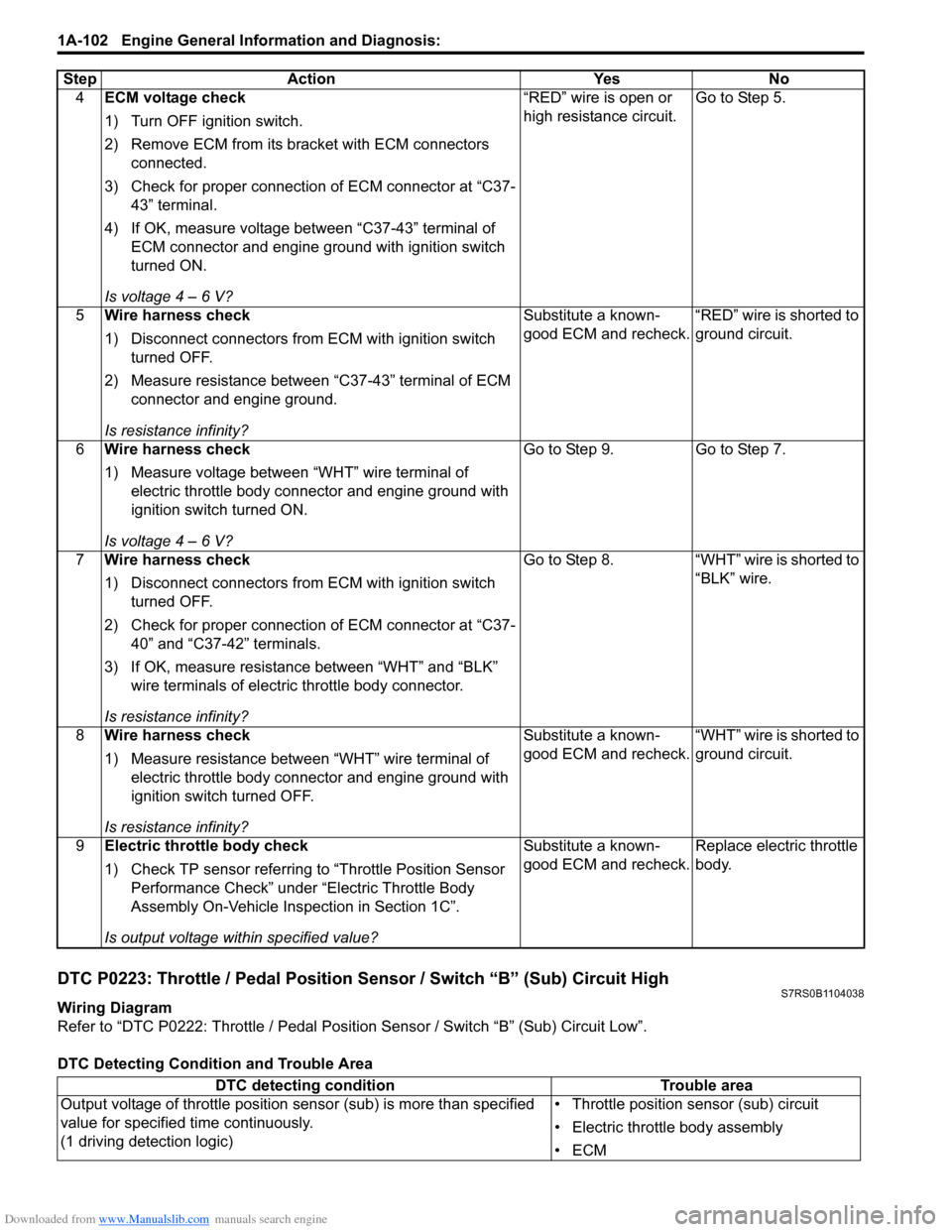
DTC P0223: Throttle / Pedal Position Sensor / Switch “B” (Sub) Circuit HighS7RS0B1104038
Wiring Diagram
Refer to “DTC P0222: Throttle / Pedal Position Sensor / Switch “B” (Sub) Circuit Low”.
DTC Detecting Condition and Trouble Area4
ECM voltage check
1) Turn OFF ignition switch.
2) Remove ECM from its br acket with ECM connectors
connected.
3) Check for proper connection of ECM connector at “C37- 43” terminal.
4) If OK, measure voltage between “C37-43” terminal of ECM connector and engine ground with ignition switch
turned ON.
Is voltage 4 – 6 V? “RED” wire is open or
high resistance circuit.
Go to Step 5.
5 Wire harness check
1) Disconnect connectors from ECM with ignition switch
turned OFF.
2) Measure resistance between “C37-43” terminal of ECM connector and engine ground.
Is resistance infinity? Substitute a known-
good ECM and recheck.
“RED” wire is shorted to
ground circuit.
6 Wire harness check
1) Measure voltage between “WHT” wire terminal of
electric throttle body connector and engine ground with
ignition switch turned ON.
Is voltage 4 – 6 V? Go to Step 9.
Go to Step 7.
7 Wire harness check
1) Disconnect connectors from ECM with ignition switch
turned OFF.
2) Check for proper connection of ECM connector at “C37- 40” and “C37-42” terminals.
3) If OK, measure resistance between “WHT” and “BLK” wire terminals of electric throttle body connector.
Is resistance infinity? Go to Step 8.
“WHT” wire is shorted to
“BLK” wire.
8 Wire harness check
1) Measure resistance between “WHT” wire terminal of
electric throttle body connector and engine ground with
ignition switch turned OFF.
Is resistance infinity? Substitute a known-
good ECM and recheck.
“WHT” wire is shorted to
ground circuit.
9 Electric throttle body check
1) Check TP sensor referring to “Throttle Position Sensor
Performance Check” under “Electric Throttle Body
Assembly On-Vehicle Inspection in Section 1C”.
Is output voltage within specified value? Substitute a known-
good ECM and recheck.
Replace electric throttle
body.
Step
Action YesNo
DTC detecting condition Trouble area
Output voltage of throttle position sensor (sub) is more than specified
value for specified time continuously.
(1 driving detection logic) • Throttle position sensor (sub) circuit
• Electric throttle body assembly
•ECM
Page 153 of 1496
Downloaded from www.Manualslib.com manuals search engine Engine General Information and Diagnosis: 1A-103
NOTE
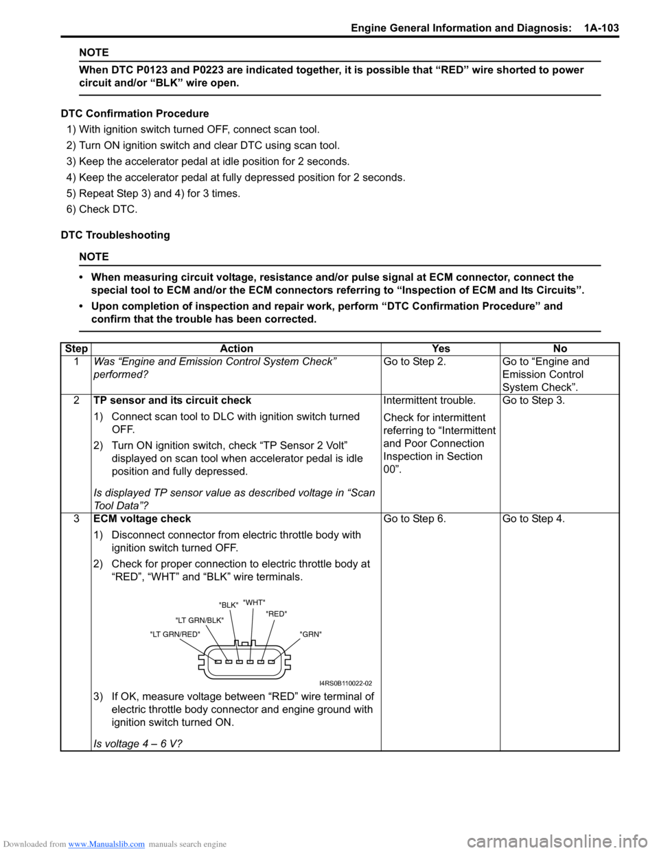
When DTC P0123 and P0223 are indicated together, it is possible that “RED” wire shorted to power
circuit and/or “BLK” wire open.
DTC Confirmation Procedure
1) With ignition switch turned OFF, connect scan tool.
2) Turn ON ignition switch and clear DTC using scan tool.
3) Keep the accelerator pedal at idle position for 2 seconds.
4) Keep the accelerator pedal at fully depressed position for 2 seconds.
5) Repeat Step 3) and 4) for 3 times.
6) Check DTC.
DTC Troubleshooting
NOTE
• When measuring circuit voltage, resistance and/ or pulse signal at ECM connector, connect the
special tool to ECM and/or the ECM connectors re ferring to “Inspection of ECM and Its Circuits”.
• Upon completion of inspection and repair work, perform “DTC Confirmation Procedure” and confirm that the trouble has been corrected.
Step Action YesNo
1 Was “Engine and Emission Control System Check”
performed? Go to Step 2.
Go to “Engine and
Emission Control
System Check”.
2 TP sensor and its circuit check
1) Connect scan tool to DLC with ignition switch turned
OFF.
2) Turn ON ignition switch, check “TP Sensor 2 Volt” displayed on scan tool when accelerator pedal is idle
position and fully depressed.
Is displayed TP sensor value as described voltage in “Scan
To o l D a t a ” ? Intermittent trouble.
Check for intermittent
referring to “Intermittent
and Poor Connection
Inspection in Section
00”.
Go to Step 3.
3 ECM voltage check
1) Disconnect connector from electric throttle body with
ignition switch turned OFF.
2) Check for proper connection to electric throttle body at “RED”, “WHT” and “BLK” wire terminals.
3) If OK, measure voltage between “RED” wire terminal of electric throttle body connector and engine ground with
ignition switch turned ON.
Is voltage 4 – 6 V? Go to Step 6.
Go to Step 4.
"GRN"
"RED"
"WHT"
"BLK"
"LT GRN/BLK"
"LT GRN/RED"
I4RS0B110022-02