Bleeder SUZUKI SWIFT 2007 2.G Service User Guide
[x] Cancel search | Manufacturer: SUZUKI, Model Year: 2007, Model line: SWIFT, Model: SUZUKI SWIFT 2007 2.GPages: 1496, PDF Size: 34.44 MB
Page 636 of 1496

Downloaded from www.Manualslib.com manuals search engine 4F-62 Electronic Stability Program:
4) Turn ignition switch to ON position and select menu “DATA LIST” mode of SUZUKI scan tool. Refer to
scan tool operator's manual for further derails.
5) When brake pedal is released, check “Master Cyl Press” under “DATA LIST” of SUZUKI scan tool.
If pressure is out of specification, replace ESP ®
hydraulic unit / cont rol module assembly.
Master cylinder pressure specification
Brake pedal released: 0 ± 0.8 MPa (0 ± 8 kg/cm2, 0
± 113 psi)
6) Hoist vehicle and remove right-side front wheel.
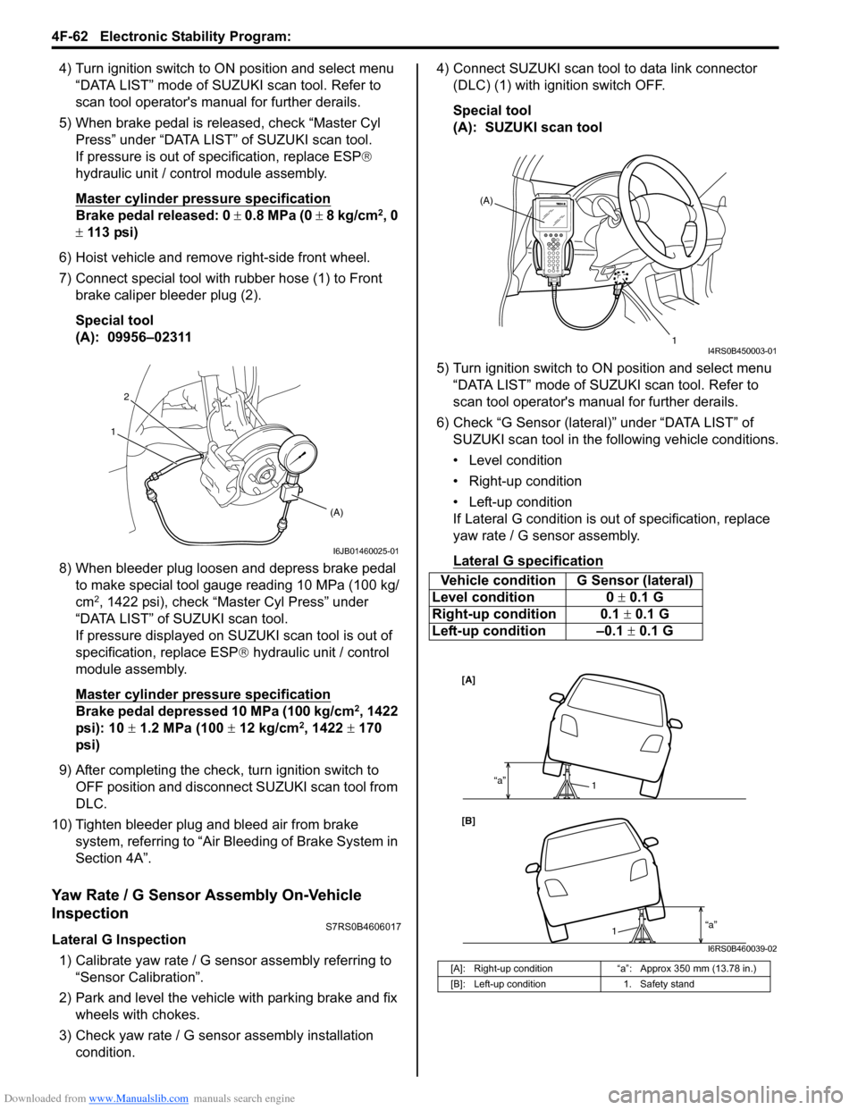
7) Connect special tool with rubber hose (1) to Front brake caliper bleeder plug (2).
Special tool
(A): 09956–02311
8) When bleeder plug loosen and depress brake pedal to make special tool gauge reading 10 MPa (100 kg/
cm
2, 1422 psi), check “Master Cyl Press” under
“DATA LIST” of SUZUKI scan tool.
If pressure displayed on SUZUKI scan tool is out of
specification, replace ESP ® hydraulic unit / control
module assembly.
Master cylinder pressure specification
Brake pedal depressed 10 MPa (100 kg/cm2, 1422
psi): 10 ± 1.2 MPa (100 ± 12 kg/cm2, 1422 ± 170
psi)
9) After completing the check, turn ignition switch to
OFF position and disconnect SUZUKI scan tool from
DLC.
10) Tighten bleeder plug and bleed air from brake system, referring to “Air Bleeding of Brake System in
Section 4A”.
Yaw Rate / G Sensor Assembly On-Vehicle
Inspection
S7RS0B4606017
Lateral G Inspection
1) Calibrate yaw rate / G sens or assembly referring to
“Sensor Calibration”.
2) Park and level the vehicle with parking brake and fix wheels with chokes.
3) Check yaw rate / G sensor assembly installation
condition. 4) Connect SUZUKI scan tool to data link connector
(DLC) (1) with ignition switch OFF.
Special tool
(A): SUZUKI scan tool
5) Turn ignition switch to ON position and select menu “DATA LIST” mode of SUZUKI scan tool. Refer to
scan tool operator's manual for further derails.
6) Check “G Sensor (lateral)” under “DATA LIST” of SUZUKI scan tool in the following vehicle conditions.
• Level condition
• Right-up condition
• Left-up condition
If Lateral G condition is ou t of specification, replace
yaw rate / G sensor assembly.
Lateral G sp ecification
2
(A)
1
I6JB01460025-01
Vehicle condition G Sensor (lateral)
Level condition 0 ± 0.1 G
Right-up condition 0.1 ± 0.1 G
Left-up condition –0.1 ± 0.1 G
[A]: Right-up condition “a”: Approx 350 mm (13.78 in.)
[B]: Left-up condition 1. Safety stand
(A)
1
I4RS0B450003-01
[A]
[B]“a”
1
“a”1
I6RS0B460039-02
Page 855 of 1496

Downloaded from www.Manualslib.com manuals search engine Clutch: 5C-3
Clutch Release Margin “C”1) Pull up parking brake fully and block wheels.
2) Start engine and keep engine at idle with neutral gear position.
3) Without clutch pedal (1) dep ressed, slightly push the
shift lever to re verse position until transaxle emits
gear contact noise. Do not shift the lever to reverse
position.
4) With emitting gear contact noise, be slow to depress clutch pedal (1), and at gear contact noise died
position (release point) stop depressing.
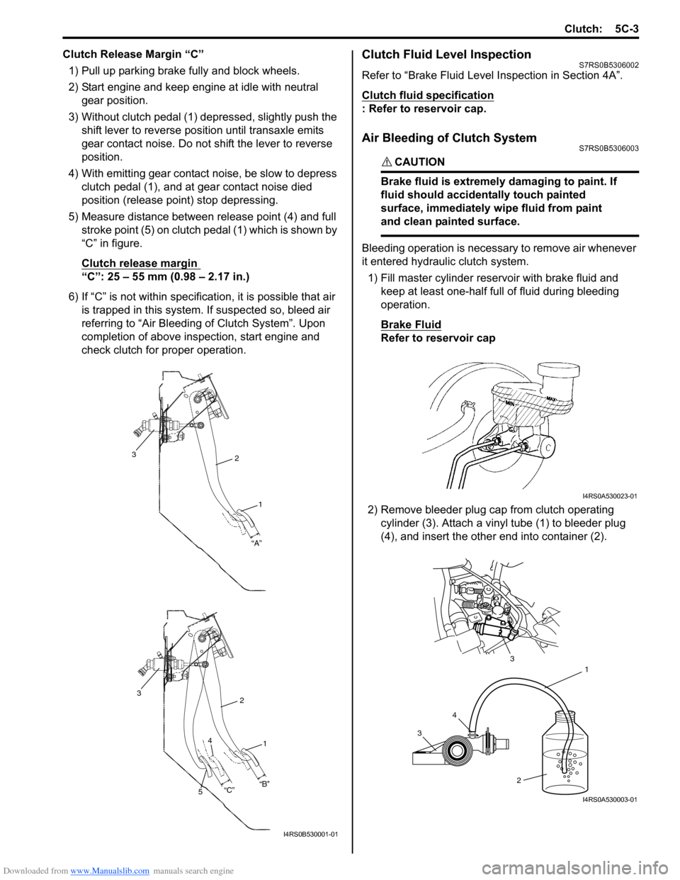
5) Measure distance between release point (4) and full stroke point (5) on clutch pedal (1) which is shown by
“C” in figure.
Clutch release margin
“C”: 25 – 55 mm (0.98 – 2.17 in.)
6) If “C” is not within specificat ion, it is possible that air
is trapped in this system. If suspected so, bleed air
referring to “Air Bleeding of Clutch System”. Upon
completion of above inspection, start engine and
check clutch for proper operation.
Clutch Fluid Level InspectionS7RS0B5306002
Refer to “Brake Fluid Level Inspection in Section 4A”.
Clutch fluid specification
: Refer to reservoir cap.
Air Bleeding of Clutch SystemS7RS0B5306003
CAUTION!
Brake fluid is extremely damaging to paint. If
fluid should accidentally touch painted
surface, immediately wipe fluid from paint
and clean painted surface.
Bleeding operation is necessary to remove air whenever
it entered hydraulic clutch system.
1) Fill master cylinder reservoir with brake fluid and keep at least one-half full of fluid during bleeding
operation.
Brake Fluid
Refer to reservoir cap
2) Remove bleeder plug cap from clutch operating cylinder (3). Attach a vinyl tube (1) to bleeder plug
(4), and insert the other end into container (2).
2
1
“A”
3
2
1
3
“B”
“C”
4
5
I4RS0B530001-01
I4RS0A530023-01
3 4 1
2
3
I4RS0A530003-01
Page 856 of 1496

Downloaded from www.Manualslib.com manuals search engine 5C-4 Clutch:
3) Depress clutch pedal several times, and then release clutch pedal, push snap ring (2) and pull pipe
connector (1) one notch.
4) When fluid pressure in cylinder is almost depleted, push pipe connector.
5) Repeat this operation until there are no more air bubbles in hydraulic line.
6) When bubbles stop, depress and hold clutch pedal, push pipe connector, and pull snap ring.
7) Then attach bleeder plug cap.
8) After completing bleeding operation, apply fluid pressure to pipe line and check for leakage.
9) Replenish fluid into reserv oir up to specified level.
10) Check clutch pedal for sponginess. If found spongy, repeat entire procedure of bleeding.Clutch Pedal Position (CPP) Switch Removal
and Installation
S7RS0B5306004
Removal
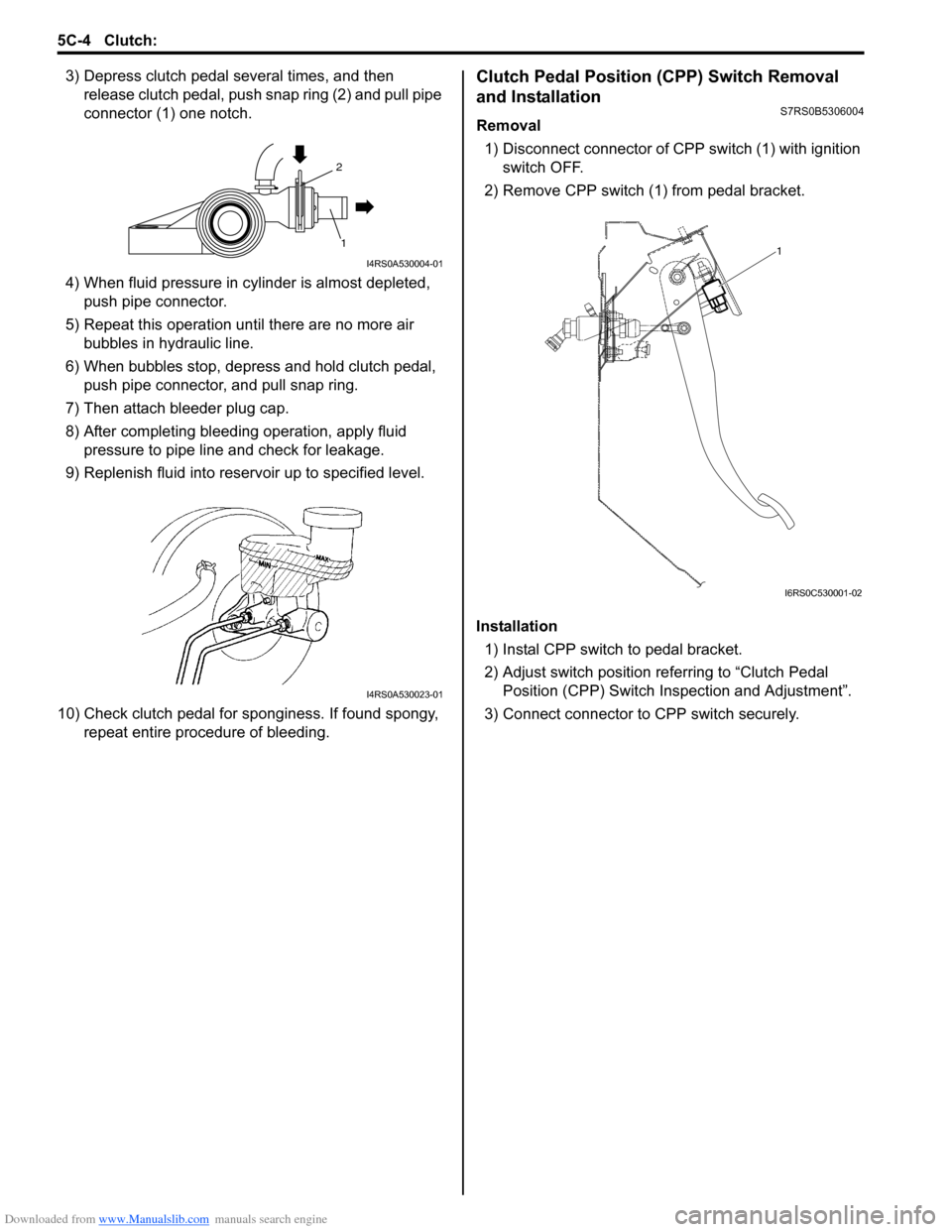
1) Disconnect connector of C PP switch (1) with ignition
switch OFF.
2) Remove CPP switch (1 ) from pedal bracket.
Installation 1) Instal CPP switch to pedal bracket.
2) Adjust switch position re ferring to “Clutch Pedal
Position (CPP) Switch Inspection and Adjustment”.
3) Connect connector to CPP switch securely.
2
1
I4RS0A530004-01
I4RS0A530023-01
1
I6RS0C530001-02