Brake control SUZUKI SWIFT 2007 2.G Service User Guide
[x] Cancel search | Manufacturer: SUZUKI, Model Year: 2007, Model line: SWIFT, Model: SUZUKI SWIFT 2007 2.GPages: 1496, PDF Size: 34.44 MB
Page 65 of 1496
![SUZUKI SWIFT 2007 2.G Service User Guide Downloaded from www.Manualslib.com manuals search engine Engine General Information and Diagnosis: 1A-15
Terminal Arrangement of ECM Coupler (Viewed from Harness Side)
[A]: Manual A/C model24. ABS /](/img/20/7607/w960_7607-64.png "SUZUKI SWIFT 2007 2.G Service User Guide Downloaded from www.Manualslib.com manuals search engine Engine General Information and Diagnosis: 1A-15
Terminal Arrangement of ECM Coupler (Viewed from Harness Side)
[A]: Manual A/C model24. ABS /")
Downloaded from www.Manualslib.com manuals search engine Engine General Information and Diagnosis: 1A-15
Terminal Arrangement of ECM Coupler (Viewed from Harness Side)
[A]: Manual A/C model24. ABS / ESP® control module 49. Radiator cooling fan motor
[B]: Auto A/C model 25. TCM 50. “RDTR FAN” fuse
1. ECM 26. To other control module connected CAN 51. A/C compressor relay
2. APP sensor assembly 27. Generator 52. Magnet clutch of compressor (A/C model)
3. Shield wire 28. Electric load current sensor (if equipped) 53. “A/C CPRSR” fuse
4. CMP sensor 29. Brake light 54. Ignition coil assembly (for No.1 and No.4 spark
plugs)
5. CKP sensor 30. Brake light switch 55. Ignition coil assembly (for No.2 and No.3 spark
plugs)
6. MAF and IAT sensor 31. Diagnosis connector (Hong Kong model) 56. P/S control module
7. MAP sensor 32. Throttle actuator control relay 57. “RADIO” fuse
8. ECT sensor 33. “THR MOT” fuse 58. Main relay
9. A/C refrigerant pressure sensor 34. Throttle throttle body assembly 59. “IG COIL” fuse
10. A/C evaporator outlet air temp. sensor (Manual A/C model) 35. Throttle actuator
60. Ignition switch
11. HO2S-1 36. TP sensor 61. “IG ACC” fuse
12. HO2S-2 37. Injector No.1 62. “FI” fuse
13. Knock sensor 38. Injector No.2 63. Starting motor control relay
14. Blower motor relay 39. Injector No.3 64. “ST SIG” fuse
15. Blower motor 40. Injector No.4 65. “ST MOT” fuse
16. Blower motor resistor 41. EVAP canister purge valve66. Transmission range switch (A/T model) or CPP
switch (Hong Kong model with M/T)
17. Blower speed selector 42. EGR valve 67. Starting motor
18. A/C switch 43. Oil control valve (Camshaft position
control) (VVT model) 68. Immobilizer coil antenna
19. Blower motor controller 44. Fuel pump relay 69. Main fuse box
20. HVAC control module 45. Fuel pump 70. Battery
21. Data link connector (DLC) 46. Radiator cooling fan motor relay No.1 71. Barometric pressure sensor
22. To other control module connected with DLC 47. Radiator cooling fan motor relay No.2
72. Engine ground
23. BCM 48. Radiator cooling fan motor relay No.3 73. Body ground
E23 C37
34
1819
567
1011
17
20
47 46
495051
2122
52 16
25 9
24
14
29
55
57 54 53
59
60 58 2
262728
15
30
56 4832 31
34353637
40
42 39 38
44
45 43 41 331
1213
238
34
1819
567
1011
17
20
47 46
495051
2122
52 16
25 9
24
14
29
55
57 54 53
59
60 58 2
262728
15
30
56 4832 31
34353637
40
42 39 38
44
45 43 41 331
1213
238
I4RS0A110008-01
Page 67 of 1496
Downloaded from www.Manualslib.com manuals search engine Engine General Information and Diagnosis: 1A-17
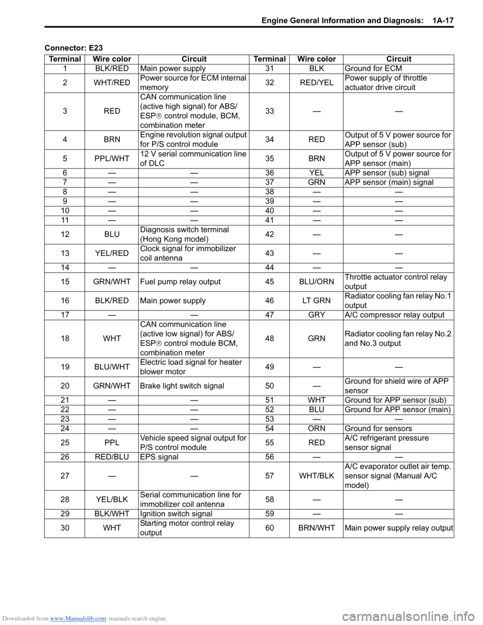
Connector: E23Terminal Wire color Circuit Terminal Wire color Circuit 1 BLK/RED Main power supply 31 BLK Ground for ECM
2WHT/RED Power source for ECM internal
memory 32 RED/YELPower supply of throttle
actuator drive circuit
3RED CAN communication line
(active high signal) for ABS/
ESP®
control module, BCM,
combination meter 33 — —
4BRN Engine revolution signal output
for P/S control module 34 REDOutput of 5 V power source for
APP sensor (sub)
5 PPL/WHT 12 V serial communication line
of DLC 35 BRNOutput of 5 V power source for
APP sensor (main)
6 — — 36 YEL APP sensor (sub) signal
7 — — 37 GRN APP sensor (main) signal
8— — 38— —
9— — 39— —
10——40—— 11——41——
12 BLU Diagnosis switch terminal
(Hong Kong model) 42 — —
13 YEL/RED Clock signal for immobilizer
coil antenna 43 — —
14——44——
15 GRN/WHT Fuel pump relay output 45 BLU/ORN Throttle actuator control relay
output
16 BLK/RED Main power supply 46 LT GRN Radiator cooling fan relay No.1
output
17 — — 47 GRY A/C compressor relay output
18 WHT CAN communication line
(active low signal) for ABS/
ESP®
control module BCM,
combination meter 48 GRN
Radiator cooling fan relay No.2
and No.3 output
19 BLU/WHT Electric load signal for heater
blower motor 49 — —
20 GRN/WHT Brake light switch signal 50 — Ground for shield wire of APP
sensor
21 — — 51 WHT Ground for APP sensor (sub)
22 — — 52 BLU Ground for APP sensor (main)
23——53——
24 — — 54 ORN Ground for sensors
25 PPL Vehicle speed signal output for
P/S control module 55 REDA/C refrigerant pressure
sensor signal
26 RED/BLU EPS signal 56 — —
27 — — 57 WHT/BLK A/C evaporator outlet air temp.
sensor signal (Manual A/C
model)
28 YEL/BLK Serial communication line for
immobilizer coil antenna 58 — —
29 BLK/WHT Ignition switch signal 59 — —
30 WHT Starting motor control relay
output 60 BRN/WHT Main power supply relay output
Page 70 of 1496
Downloaded from www.Manualslib.com manuals search engine 1A-20 Engine General Information and Diagnosis:
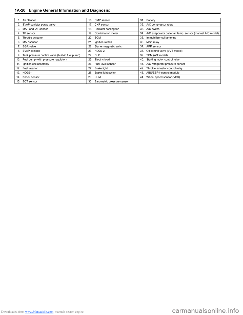
1. Air cleaner16. CMP sensor31. Battery
2. EVAP canister purge valve 17. CKP sensor32. A/C compressor relay
3. MAF and IAT sensor 18. Radiator cooling fan33. A/C switch
4. TP sensor 19. Combination meter34. A/C evaporator outlet air temp. sensor (manual A/C model)
5. Throttle actuator 20. BCM35.Immobilizer coil antenna
6. MAP sensor 21. Ignition switch36. Main relay
7. EGR valve 22. Starter magnetic switch37. APP sensor
8. EVAP canister 23. HO2S-238. Oil control valve (VVT model)
9. Tank pressure control valve (built-in fuel pump) 24. DLC 39. TCM (A/T model)
10. Fuel pump (with pressure regulator) 25. Electric load40. Starting motor control relay
11. Ignition coil assembly 26. Fuel level sensor41. A/C refrigerant pressure sensor
12. Fuel injector 27. Brake light42. Throttle actuator control relay
13. HO2S-1 28. Brake light switch43. ABS/ESP® control module
14. Knock sensor 29. ECM44. Wheel speed sensor (VSS)
15. ECT sensor 30. Barometric pressure sensor
Page 71 of 1496
Downloaded from www.Manualslib.com manuals search engine Engine General Information and Diagnosis: 1A-21
Component Location
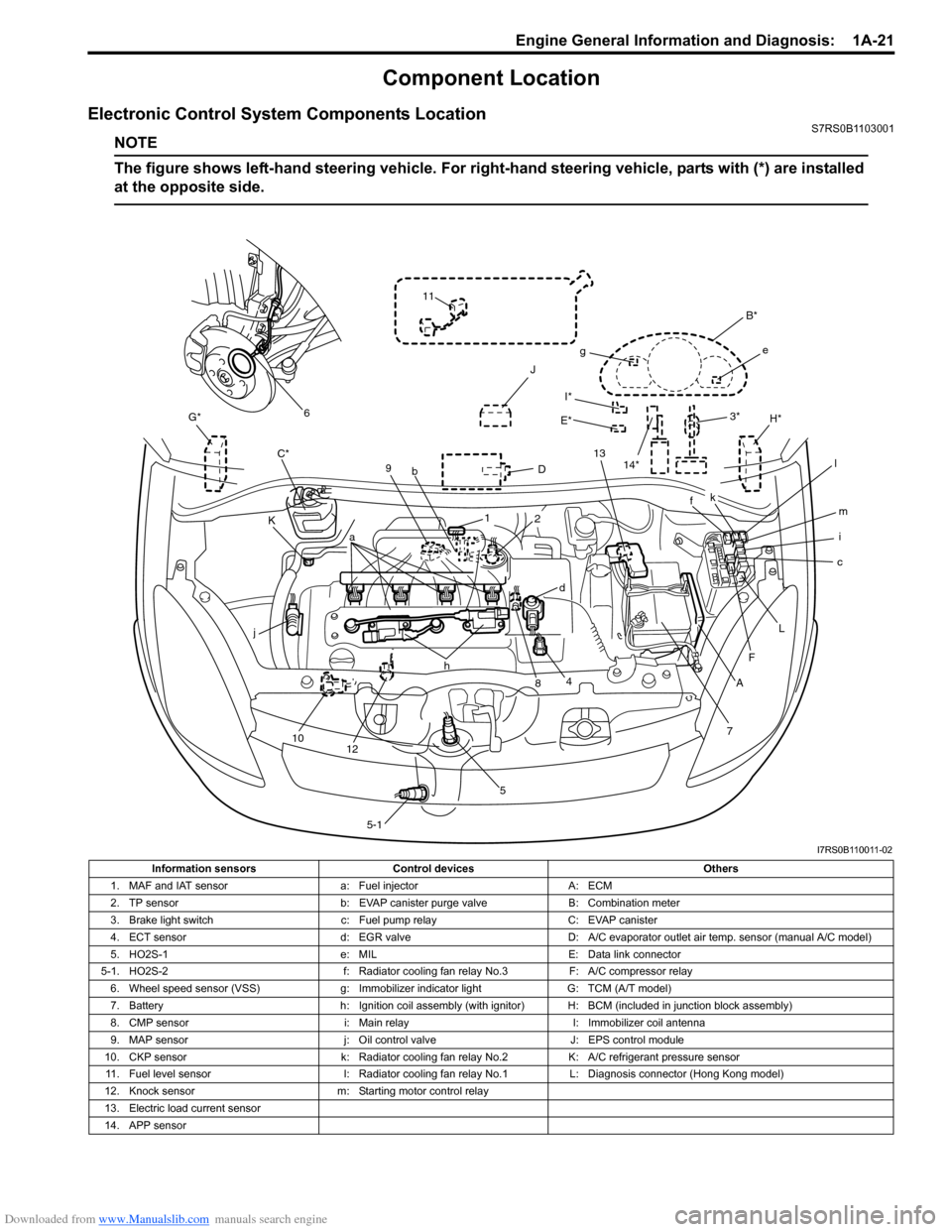
Electronic Control System Components LocationS7RS0B1103001
NOTE
The figure shows left-hand steering vehicle. For right-hand steering vehicle, parts with (*) are installed
at the opposite side.
I*
E*
G*
D
K H*
J
C*
7
A
F
c
L
i m
f
B*
e
g
k
l
13
3*
4
j
10 12 h
58
a
9
b
1
5-1
d
2
11
6
14*
I7RS0B110011-02
Information sensors Control devices Others
1. MAF and IAT sensor a: Fuel injectorA: ECM
2. TP sensor b: EVAP canister purge valve B: Combination meter
3. Brake light switch c: Fuel pump relayC: EVAP canister
4. ECT sensor d: EGR valveD: A/C evaporator outlet air temp. sensor (manual A/C model)
5. HO2S-1 e: MILE: Data link connector
5-1. HO2S-2 f: Radiator cooling fan relay No.3F: A/C compressor relay
6. Wheel speed sensor (VSS) g: Immobilizer indicator lightG: TCM (A/T model)
7. Battery h: Ignition coil assembly (with ignitor) H: BCM (included in junction block assembly)
8. CMP sensor i: Main relayI: Immobilizer coil antenna
9. MAP sensor j: Oil control valveJ: EPS control module
10. CKP sensor k: Radiator cooling fan relay No.2K: A/C refrigerant pressure sensor
11. Fuel level sensor l: Radiator cooling fan relay No.1L: Diagnosis connector (Hong Kong model)
12. Knock sensor m: Starting motor control relay
13. Electric load current sensor
14. APP sensor
Page 83 of 1496
Downloaded from www.Manualslib.com manuals search engine Engine General Information and Diagnosis: 1A-33
Scan Tool DataS7RS0B1104007
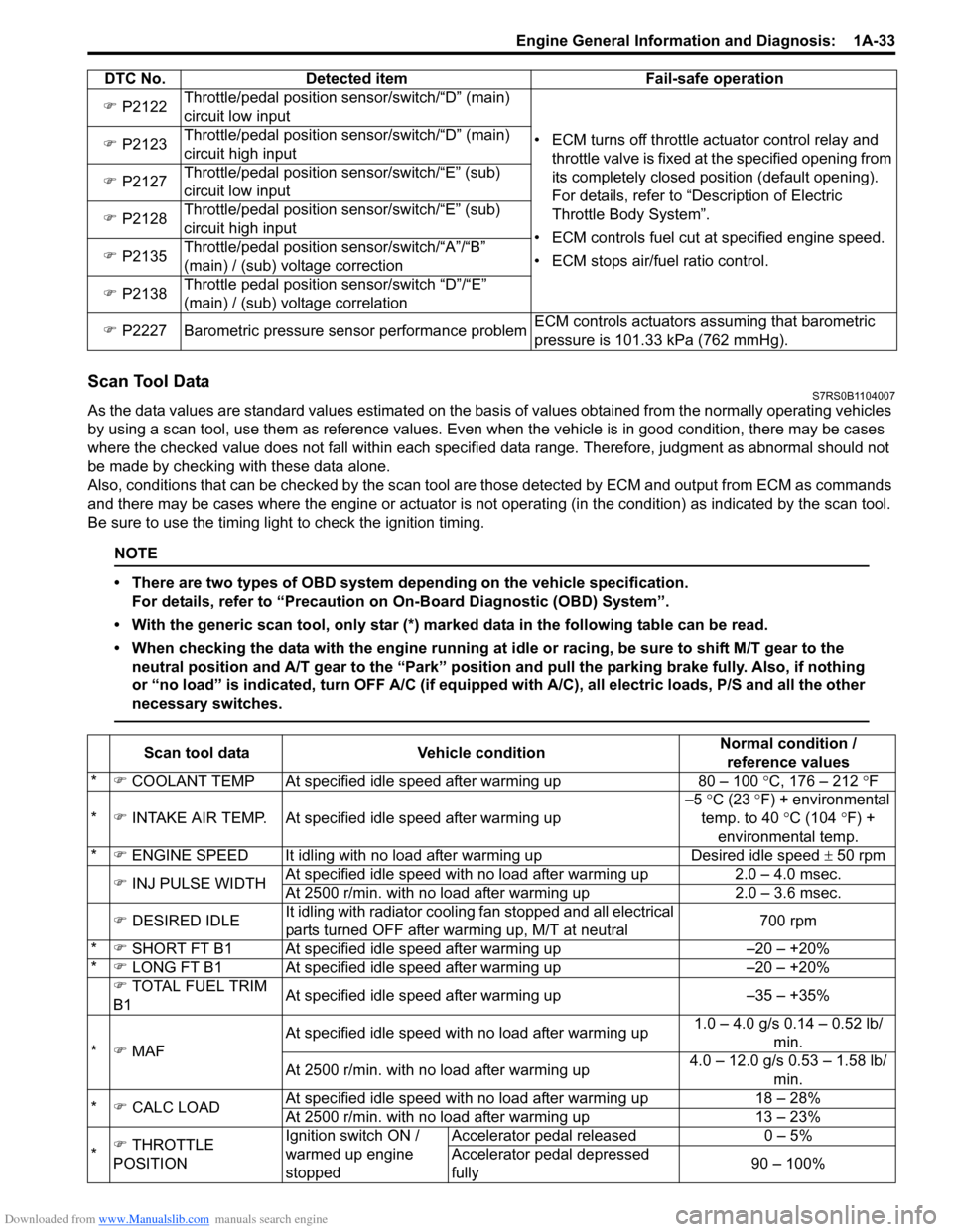
As the data values are standard values estimated on the basis of values obtained from the normally operating vehicles
by using a scan tool, use them as re ference values. Even when the vehicle is in good condition, there may be cases
where the checked value does not fall within each specified data range. Therefore, judgment as abnormal should not
be made by checking with these data alone.
Also, conditions that can be checked by the scan tool are those detected by ECM and output from ECM as commands
and there may be cases where the engine or actuator is not operating (in the condition) as indicated by the scan tool.
Be sure to use the timing light to check the ignition timing.
NOTE
• There are two types of OBD system depending on the vehicle specification.
For details, refer to “Precaution on On-Board Diagnostic (OBD) System”.
• With the generic scan tool, only star (*) marked data in the following table can be read.
• When checking the data with the engine running at idle or racing, be sure to shift M/T gear to the neutral position and A/T gear to the “Park” position and pull the parking brake fully. Also, if nothing
or “no load” is indicated, turn O FF A/C (if equipped with A/C), all electric loads, P/S and all the other
necessary switches.
) P2122 Throttle/pedal position sensor/switch/“D” (main)
circuit low input
• ECM turns off throttle actuator control relay and throttle valve is fixed at the specified opening from
its completely closed position (default opening).
For details, refer to “Description of Electric
Throttle Body System”.
• ECM controls fuel cut at specified engine speed.
• ECM stops air/fuel ratio control.
)
P2123 Throttle/pedal position sensor/switch/“D” (main)
circuit high input
) P2127 Throttle/pedal position sensor/switch/“E” (sub)
circuit low input
) P2128 Throttle/pedal position sensor/switch/“E” (sub)
circuit high input
) P2135 Throttle/pedal position sensor/switch/“A”/“B”
(main) / (sub) voltage correction
) P2138 Throttle pedal position sensor/switch “D”/“E”
(main) / (sub) voltage correlation
) P2227 Barometric pressure sensor performance problem ECM controls actuators assuming that barometric
pressure is 101.33 kPa (762 mmHg).
DTC No. Detected item Fail-safe operation
Scan tool data
Vehicle condition Normal condition /
reference values
* ) COOLANT TEMP At specified idle speed after warming up 80 – 100 °C, 176 – 212 °F
* ) INTAKE AIR TEMP. At specifie d idle speed after warming up –5
°C (23 °F) + environmental
temp. to 40 °C (104 °F) +
environmental temp.
* ) ENGINE SPEED It idling with no load after warming upDesired idle speed ± 50 rpm
) INJ PULSE WIDTH At specified idle speed with no load after warming up
2.0 – 4.0 msec.
At 2500 r/min. with no load after warming up 2.0 – 3.6 msec.
) DESIRED IDLE It idling with radiator cooling fan stopped and all electrical
parts turned OFF after warming up, M/T at neutral 700 rpm
* ) SHORT FT B1 At specified idle speed after warming up –20 – +20%
* ) LONG FT B1 At specified idle speed after warming up –20 – +20%
) TOTAL FUEL TRIM
B1 At specified idle speed after warming up
–35 – +35%
* ) MAF At specified idle speed wit
h no load after warming up 1.0 – 4.0 g/s 0.14 – 0.52 lb/
min.
At 2500 r/min. with no load after warming up 4.0 – 12.0 g/s 0.53 – 1.58 lb/
min.
* ) CALC LOAD At specified idle speed with no load after warming up
18 – 28%
At 2500 r/min. with no load after warming up 13 – 23%
* )
THROTTLE
POSITION Ignition switch ON /
warmed up engine
stoppedAccelerator pedal released
0 – 5%
Accelerator pedal depressed
fully 90 – 100%
Page 86 of 1496
Downloaded from www.Manualslib.com manuals search engine 1A-36 Engine General Information and Diagnosis:
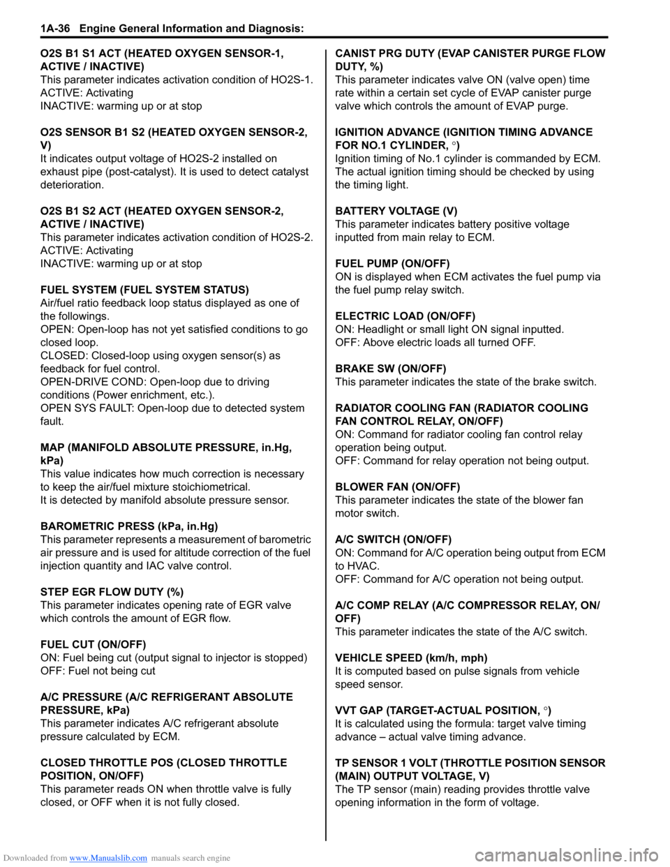
O2S B1 S1 ACT (HEATED OXYGEN SENSOR-1,
ACTIVE / INACTIVE)
This parameter indicates activation condition of HO2S-1.
ACTIVE: Activating
INACTIVE: warming up or at stop
O2S SENSOR B1 S2 (HEATED OXYGEN SENSOR-2,
V)
It indicates output voltage of HO2S-2 installed on
exhaust pipe (post-catalyst). It is used to detect catalyst
deterioration.
O2S B1 S2 ACT (HEATED OXYGEN SENSOR-2,
ACTIVE / INACTIVE)
This parameter indicates acti vation condition of HO2S-2.
ACTIVE: Activating
INACTIVE: warming up or at stop
FUEL SYSTEM (FUEL SYSTEM STATUS)
Air/fuel ratio feedback loop status displayed as one of
the followings.
OPEN: Open-loop has not yet satisfied conditions to go
closed loop.
CLOSED: Closed-loop using oxygen sensor(s) as
feedback for fuel control.
OPEN-DRIVE COND: Open-loop due to driving
conditions (Power enrichment, etc.).
OPEN SYS FAULT: Open-loop due to detected system
fault.
MAP (MANIFOLD ABSOLUTE PRESSURE, in.Hg,
kPa)
This value indicates how much correction is necessary
to keep the air/fuel mixture stoichiometrical.
It is detected by manifold absolute pressure sensor.
BAROMETRIC PRESS (kPa, in.Hg)
This parameter represents a measurement of barometric
air pressure and is used for al titude correction of the fuel
injection quantity and IAC valve control.
STEP EGR FLOW DUTY (%)
This parameter indicates opening rate of EGR valve
which controls the amount of EGR flow.
FUEL CUT (ON/OFF)
ON: Fuel being cut (output signal to injector is stopped)
OFF: Fuel not being cut
A/C PRESSURE (A/C REFRIGERANT ABSOLUTE
PRESSURE, kPa)
This parameter indicates A/C refrigerant absolute
pressure calculated by ECM.
CLOSED THROTTLE PO S (CLOSED THROTTLE
POSITION, ON/OFF)
This parameter reads ON wh en throttle valve is fully
closed, or OFF when it is not fully closed. CANIST PRG DUTY (EVAP CANISTER PURGE FLOW
DUTY, %)
This parameter indicates valve ON (valve open) time
rate within a certain set cycle of EVAP canister purge
valve which controls the amount of EVAP purge.
IGNITION ADVANCE (IGNITION TIMING ADVANCE
FOR NO.1 CYLINDER,
°)
Ignition timing of No.1 cylinder is commanded by ECM.
The actual ignition timing should be checked by using
the timing light.
BATTERY VOLTAGE (V)
This parameter indicates battery positive voltage
inputted from main relay to ECM.
FUEL PUMP (ON/OFF)
ON is displayed when ECM activates the fuel pump via
the fuel pump relay switch.
ELECTRIC LOAD (ON/OFF)
ON: Headlight or small light ON signal inputted.
OFF: Above electric loads all turned OFF.
BRAKE SW (ON/OFF)
This parameter indicates the state of the brake switch.
RADIATOR COOLING FAN (RADIATOR COOLING
FAN CONTROL RELAY, ON/OFF)
ON: Command for radiator cooling fan control relay
operation being output.
OFF: Command for relay operation not being output.
BLOWER FAN (ON/OFF)
This parameter indicates the state of the blower fan
motor switch.
A/C SWITCH (ON/OFF)
ON: Command for A/C operatio n being output from ECM
to HVAC.
OFF: Command for A/C oper ation not being output.
A/C COMP RELAY (A/C COMPRESSOR RELAY, ON/
OFF)
This parameter indicates the state of the A/C switch.
VEHICLE SPEED (km/h, mph)
It is computed based on pulse signals from vehicle
speed sensor.
VVT GAP (TARGET-ACTUAL POSITION, °)
It is calculated using the formula: target valve timing
advance – actual valve timing advance.
TP SENSOR 1 VOLT (THROTTLE POSITION SENSOR
(MAIN) OUTPUT VOLTAGE, V)
The TP sensor (main) reading provides throttle valve
opening information in the form of voltage.
Page 92 of 1496
Downloaded from www.Manualslib.com manuals search engine 1A-42 Engine General Information and Diagnosis:
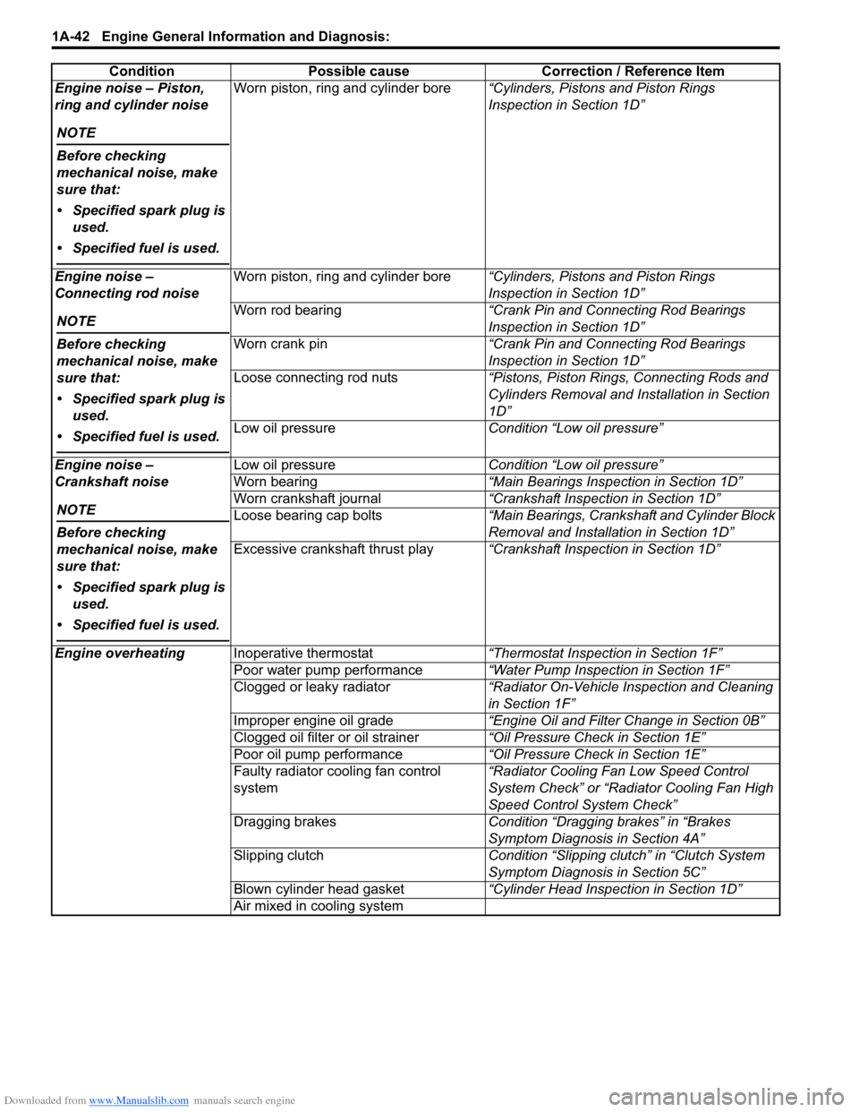
Engine noise – Piston,
ring and cylinder noise
NOTE
Before checking
mechanical noise, make
sure that:
• Specified spark plug is used.
• Specified fuel is used.
Worn piston, ring and cylinder bore “Cylinders, Pistons and Piston Rings
Inspection in Section 1D”
Engine noise –
Connecting rod noise
NOTE
Before checking
mechanical noise, make
sure that:
• Specified spark plug is used.
• Specified fuel is used.
Worn piston, ring and cylinder bore “Cylinders, Pistons and Piston Rings
Inspection in Section 1D”
Worn rod bearing “Crank Pin and Connecting Rod Bearings
Inspection in Section 1D”
Worn crank pin “Crank Pin and Connecting Rod Bearings
Inspection in Section 1D”
Loose connecting rod nuts “Pistons, Piston Rings, Connecting Rods and
Cylinders Removal and Installation in Section
1D”
Low oil pressure Condition “Low oil pressure”
Engine noise –
Crankshaft noise
NOTE
Before checking
mechanical noise, make
sure that:
• Specified spark plug is used.
• Specified fuel is used.
Low oil pressure Condition “Low oil pressure”
Worn bearing “Main Bearings Inspection in Section 1D”
Worn crankshaft journal “Crankshaft Inspection in Section 1D”
Loose bearing cap bolts “Main Bearings, Crankshaft and Cylinder Block
Removal and Installation in Section 1D”
Excessive crankshaft thrust play “Crankshaft Inspection in Section 1D”
Engine overheating Inoperative thermostat “Thermostat Inspection in Section 1F”
Poor water pump performance “Water Pump Inspection in Section 1F”
Clogged or leaky radiator “Radiator On-Vehicle Inspection and Cleaning
in Section 1F”
Improper engine oil grade “Engine Oil and Filter Change in Section 0B”
Clogged oil filter or oil strainer “Oil Pressure Check in Section 1E”
Poor oil pump performance “Oil Pressure Check in Section 1E”
Faulty radiator cooling fan control
system “Radiator Cooling Fan Low Speed Control
System Check” or “Rad
iator Cooling Fan High
Speed Control System Check”
Dragging brakes Condition “Dragging brakes” in “Brakes
Symptom Diagnosis in Section 4A”
Slipping clutch Condition “Slipping clutch” in “Clutch System
Symptom Diagnosis in Section 5C”
Blown cylinder head gasket “Cylinder Head Inspection in Section 1D”
Air mixed in cooling system
Condition Possible cause Correction / Reference Item
Page 93 of 1496
Downloaded from www.Manualslib.com manuals search engine Engine General Information and Diagnosis: 1A-43
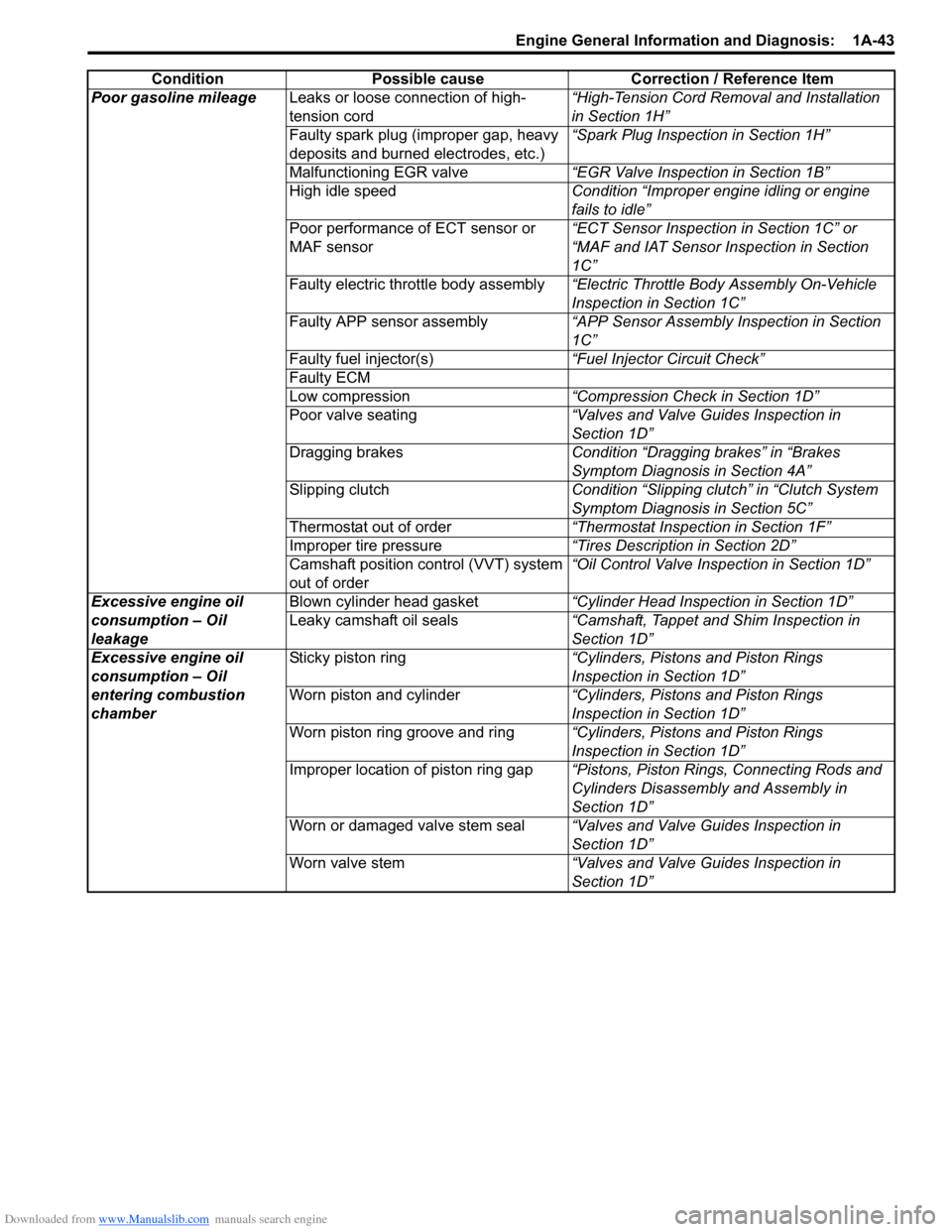
Poor gasoline mileageLeaks or loose connection of high-
tension cord “High-Tension Cord Removal and Installation
in Section 1H”
Faulty spark plug (improper gap, heavy
deposits and burned electrodes, etc.) “Spark Plug Inspection in Section 1H”
Malfunctioning EGR valve “EGR Valve Inspection in Section 1B”
High idle speed Condition “Improper engine idling or engine
fails to idle”
Poor performance of ECT sensor or
MAF sensor “ECT Sensor Inspection in Section 1C” or
“MAF and IAT Sensor Inspection in Section
1C”
Faulty electric throttle body assembly “Electric Throttle Body Assembly On-Vehicle
Inspection in Section 1C”
Faulty APP sensor assembly “APP Sensor Assembly Inspection in Section
1C”
Faulty fuel injector(s) “Fuel Injector Circuit Check”
Faulty ECM
Low compression “Compression Check in Section 1D”
Poor valve seating “Valves and Valve Guides Inspection in
Section 1D”
Dragging brakes Condition “Dragging brakes” in “Brakes
Symptom Diagnosis in Section 4A”
Slipping clutch Condition “Slipping clutch” in “Clutch System
Symptom Diagnosis in Section 5C”
Thermostat out of order “Thermostat Inspection in Section 1F”
Improper tire pressure “Tires Description in Section 2D”
Camshaft position control (VVT) system
out of order “Oil Control Valve Inspection in Section 1D”
Excessive engine oil
consumption – Oil
leakage Blown cylinder head gasket
“Cylinder Head Inspection in Section 1D”
Leaky camshaft oil seals “Camshaft, Tappet and Shim Inspection in
Section 1D”
Excessive engine oil
consumption – Oil
entering combustion
chamber Sticky piston ring
“Cylinders, Pistons and Piston Rings
Inspection in Section 1D”
Worn piston and cylinder “Cylinders, Pistons and Piston Rings
Inspection in Section 1D”
Worn piston ring groove and ring “Cylinders, Pistons and Piston Rings
Inspection in Section 1D”
Improper location of piston ring gap “Pistons, Piston Rings, Connecting Rods and
Cylinders Disassembly and Assembly in
Section 1D”
Worn or damaged valve stem seal “Valves and Valve Guides Inspection in
Section 1D”
Worn valve stem “Valves and Valve Guides Inspection in
Section 1D”
Condition Possible cause Correction / Reference Item
Page 95 of 1496
Downloaded from www.Manualslib.com manuals search engine Engine General Information and Diagnosis: 1A-45
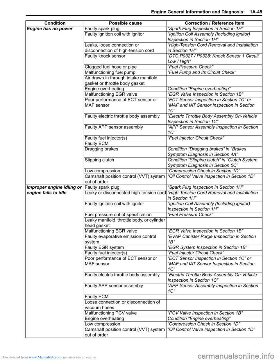
Engine has no powerFaulty spark plug “Spark Plug Inspection in Section 1H”
Faulty ignition coil with ignitor “Ignition Coil Assembly (Including ignitor)
Inspection in Section 1H”
Leaks, loose connection or
disconnection of high-tension cord “High-Tension Cord Removal and Installation
in Section 1H”
Faulty knock sensor “DTC P0327 / P0328: Knock Sensor 1 Circuit
Low / High”
Clogged fuel hose or pipe “Fuel Pressure Check”
Malfunctioning fuel pump “Fuel Pump and Its Circuit Check”
Air drawn in through intake manifold
gasket or throttle body gasket
Engine overheating Condition “Engine overheating”
Malfunctioning EGR valve “EGR Valve Inspection in Section 1B”
Poor performance of ECT sensor or
MAF sensor “ECT Sensor Inspection in Section 1C” or
“MAF and IAT Sensor Inspection in Section
1C”
Faulty electric throttle body assembly “Electric Throttle Body Assembly On-Vehicle
Inspection in Section 1C”
Faulty APP sensor assembly “APP Sensor Assembly Inspection in Section
1C”
Faulty fuel injector(s) “Fuel Injector Circuit Check”
Faulty ECM
Dragging brakes Condition “Dragging brakes” in “Brakes
Symptom Diagnosis in Section 4A”
Slipping clutch Condition “Slipping clutch” in “Clutch System
Symptom Diagnosis in Section 5C”
Low compression “Compression Check in Section 1D”
Camshaft position control (VVT) system
out of order “Oil Control Valve Inspection in Section 1D”
Improper engine idling or
engine fails to idle Faulty spark plug
“Spark Plug Inspection in Section 1H”
Leaky or disconnected high-tension cord “High-Tension Cord Removal and Installation
in Section 1H”
Faulty ignition coil with ignitor “Ignition Coil Assembly (Including ignitor)
Inspection in Section 1H”
Fuel pressure out of specification “Fuel Pressure Check”
Leaky manifold, throttle body, or cylinder
head gasket
Malfunctioning EGR valve “EGR Valve Inspection in Section 1B”
Faulty evaporative emission control
system “EVAP Canister Purge Inspection in Section
1B”
Faulty EGR system “EGR System Inspection in Section 1B”
Faulty fuel injector(s) “Fuel Injector Circuit Check”
Poor performance of ECT sensor or
MAF sensor “ECT Sensor Inspection in Section 1C” or
“MAF and IAT Sensor Inspection in Section
1C”
Faulty electric throttle body assembly “Electric Throttle Body Assembly On-Vehicle
Inspection in Section 1C”
Faulty APP sensor assembly “APP Sensor Assembly Inspection in Section
1C”
Faulty ECM
Loose connection or disconnection of
vacuum hoses
Malfunctioning PCV valve “PCV Valve Inspection in Section 1B”
Engine overheating Condition “Engine overheating”
Low compression “Compression Check in Section 1D”
Camshaft position control (VVT) system
out of order “Oil Control Valve Inspection in Section 1D”
Condition Possible cause Correction / Reference Item
Page 139 of 1496
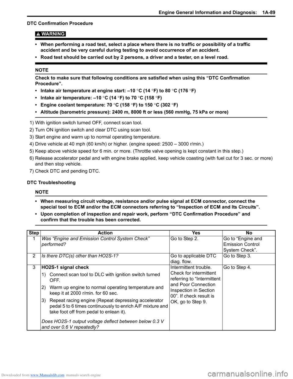
Downloaded from www.Manualslib.com manuals search engine Engine General Information and Diagnosis: 1A-89
DTC Confirmation Procedure
WARNING!
• When performing a road test, select a place where there is no traffic or possibility of a traffic accident and be very careful during testing to avoid occurrence of an accident.
• Road test should be carried out by 2 persons, a driver and a tester, on a level road.
NOTE
Check to make sure that following conditions ar e satisfied when using this “DTC Confirmation
Procedure”.
• Intake air temperature at engine start: –10 °C (14 ° F) to 80 °C (176 °F)
• Intake air temperature: –10 °C (14 °F) to 70 °C (158 °F)
• Engine coolant temperature: 70 °C (158 °F) to 150 °C (302 °F)
• Altitude (barometric pressure): 2400 m, 8000 ft or less (560 mmHg, 75 kPa or more)
1) With ignition switch turned OFF, connect scan tool.
2) Turn ON ignition switch and clear DTC using scan tool.
3) Start engine and warm up to normal operating temperature.
4) Drive vehicle at 40 mph (60 km/h) or higher. (engine speed: 2500 – 3000 r/min.)
5) Keep above vehicle speed for 6 min. or more. (Throt tle valve opening is kept constant in this step.)
6) Release accelerator pedal and with engine brake applied, keep vehicle coasting (with fuel cut for 3 sec. or more)
and then stop vehicle.
7) Check DTC and pending DTC.
DTC Troubleshooting
NOTE
• When measuring circuit voltage, resistance and/ or pulse signal at ECM connector, connect the
special tool to ECM and/or the ECM connectors re ferring to “Inspection of ECM and Its Circuits”.
• Upon completion of inspection and repair work, perform “DTC Confirmation Procedure” and confirm that the trouble has been corrected.
Step Action YesNo
1 Was “Engine and Emission Control System Check”
performed? Go to Step 2.
Go to “Engine and
Emission Control
System Check”.
2 Is there DTC(s) other than HO2S-1? Go to applicable DTC
diag. flow.Go to Step 3.
3 HO2S-1 signal check
1) Connect scan tool to DLC with ignition switch turned
OFF.
2) Warm up engine to normal operating temperature and keep it at 2000 r/min. for 60 sec.
3) Repeat racing engine (Repeat depressing accelerator pedal 5 to 6 times continuous ly to enrich A/F mixture and
take foot off from pedal to enlean it).
Does HO2S-1 output voltage deflect between below 0.3 V
and over 0.6 V repeatedly? Intermittent trouble.
Check for intermittent
referring to “Intermittent
and Poor Connection
Inspection in Section
00”. If check result is
OK, go to Step 9.
Go to Step 4.