Evap canister inspection SUZUKI SWIFT 2007 2.G Service User Guide
[x] Cancel search | Manufacturer: SUZUKI, Model Year: 2007, Model line: SWIFT, Model: SUZUKI SWIFT 2007 2.GPages: 1496, PDF Size: 34.44 MB
Page 271 of 1496
Downloaded from www.Manualslib.com manuals search engine Aux. Emission Control Devices: 1B-4
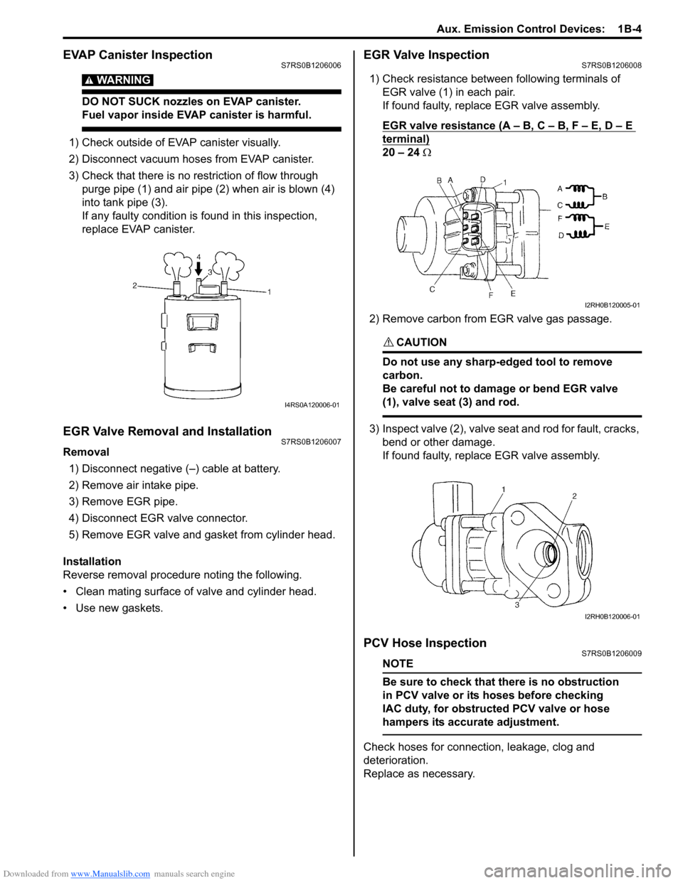
EVAP Canister InspectionS7RS0B1206006
WARNING!
DO NOT SUCK nozzles on EVAP canister.
Fuel vapor inside EVAP canister is harmful.
1) Check outside of EVAP canister visually.
2) Disconnect vacuum hoses from EVAP canister.
3) Check that there is no restriction of flow through purge pipe (1) and air pipe (2) when air is blown (4)
into tank pipe (3).
If any faulty condition is found in this inspection,
replace EVAP canister.
EGR Valve Removal and InstallationS7RS0B1206007
Removal
1) Disconnect negative (–) cable at battery.
2) Remove air intake pipe.
3) Remove EGR pipe.
4) Disconnect EGR valve connector.
5) Remove EGR valve and gasket from cylinder head.
Installation
Reverse removal procedure noting the following.
• Clean mating surface of valve and cylinder head.
• Use new gaskets.
EGR Valve InspectionS7RS0B1206008
1) Check resistance between following terminals of EGR valve (1) in each pair.
If found faulty, replace EGR valve assembly.
EGR valve resistance (A – B, C – B, F – E, D – E
terminal)
20 – 24 Ω
2) Remove carbon from EGR valve gas passage.
CAUTION!
Do not use any sharp-edged tool to remove
carbon.
Be careful not to damage or bend EGR valve
(1), valve seat (3) and rod.
3) Inspect valve (2), valve seat and rod for fault, cracks, bend or other damage.
If found faulty, replace EGR valve assembly.
PCV Hose InspectionS7RS0B1206009
NOTE
Be sure to check that there is no obstruction
in PCV valve or its hoses before checking
IAC duty, for obstructed PCV valve or hose
hampers its accurate adjustment.
Check hoses for connection, leakage, clog and
deterioration.
Replace as necessary.
I4RS0A120006-01
I2RH0B120005-01
I2RH0B120006-01
Page 298 of 1496
Downloaded from www.Manualslib.com manuals search engine 1D-13 Engine Mechanical:
Throttle Body On-Vehicle InspectionS7RS0B1406006
Check electric throttle body assembly referring to
“Throttle Valve Operation Check” and “Electric Throttle
Body Assembly Operation Check” under “Electric
Throttle Body Assembly On-Vehicle Inspection in
Section 1C”.
Electric Throttle Body Assembly Removal and
Installation
S7RS0B1406007
CAUTION!
Never disassemble electric throttle body.
Disassembly will spoil its original
performance. If faulty condition is found,
replace it with new one.
NOTE
After replacing electric throttle body
assembly, perform calibration of throttle
valve referring to “Electric Throttle Body
System Calibration in Section 1C”.
Removal
1) Disconnect negative cable at battery.
2) Drain coolant referring to “Cooling System Draining in Section 1F”.
3) Remove air cleaner assembly referring to “Air Cleaner Components”.
4) Detach EVAP canister and purge valve chamber, and remove air cleaner outlet hose.
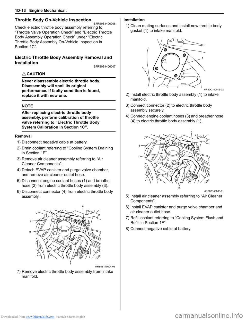
5) Disconnect engine coolant hoses (1) and breather hose (2) from electric throttle body assembly (3).
6) Disconnect connector (4) from electric throttle body assembly.
7) Remove electric throttle body assembly from intake
manifold. Installation
1) Clean mating surfaces and install new throttle body gasket (1) to intake manifold.
2) Install electric throttle bo dy assembly (1) to intake
manifold.
3) Connect connector (2) to electric throttle body assembly securely.
4) Connect engine coolant hoses (3) and breather hose (4) to electric thrott le body assembly (1).
5) Install air cleaner assembly referring to “Air Cleaner
Components”.
6) Install EVAP canister and purge valve chamber and air cleaner outlet hose.
7) Refill coolant referring to “Cooling System Flush and
Refill in Section 1F”.
8) Connect negative cable at battery.
2
4
3
1I4RS0B140004-02
1
I6RS0C140013-02
4
2
1
3I4RS0B140006-01
Page 299 of 1496
Downloaded from www.Manualslib.com manuals search engine Engine Mechanical: 1D-14
Throttle Body CleaningS7RS0B1406008
Clean electric throttle body assembly referring to
“Throttle Valve Visual Check” under “Electric Throttle
Body Assembly On-Vehicle Inspection in Section 1C”.
Intake Manifold Removal and InstallationS7RS0B1406009
Removal1) Remove cowl top plate referring to “Cowl Top Components in Section 9K”.
2) Remove throttle body referring to “Electric Throttle Body Assembly Removal and Installation”.
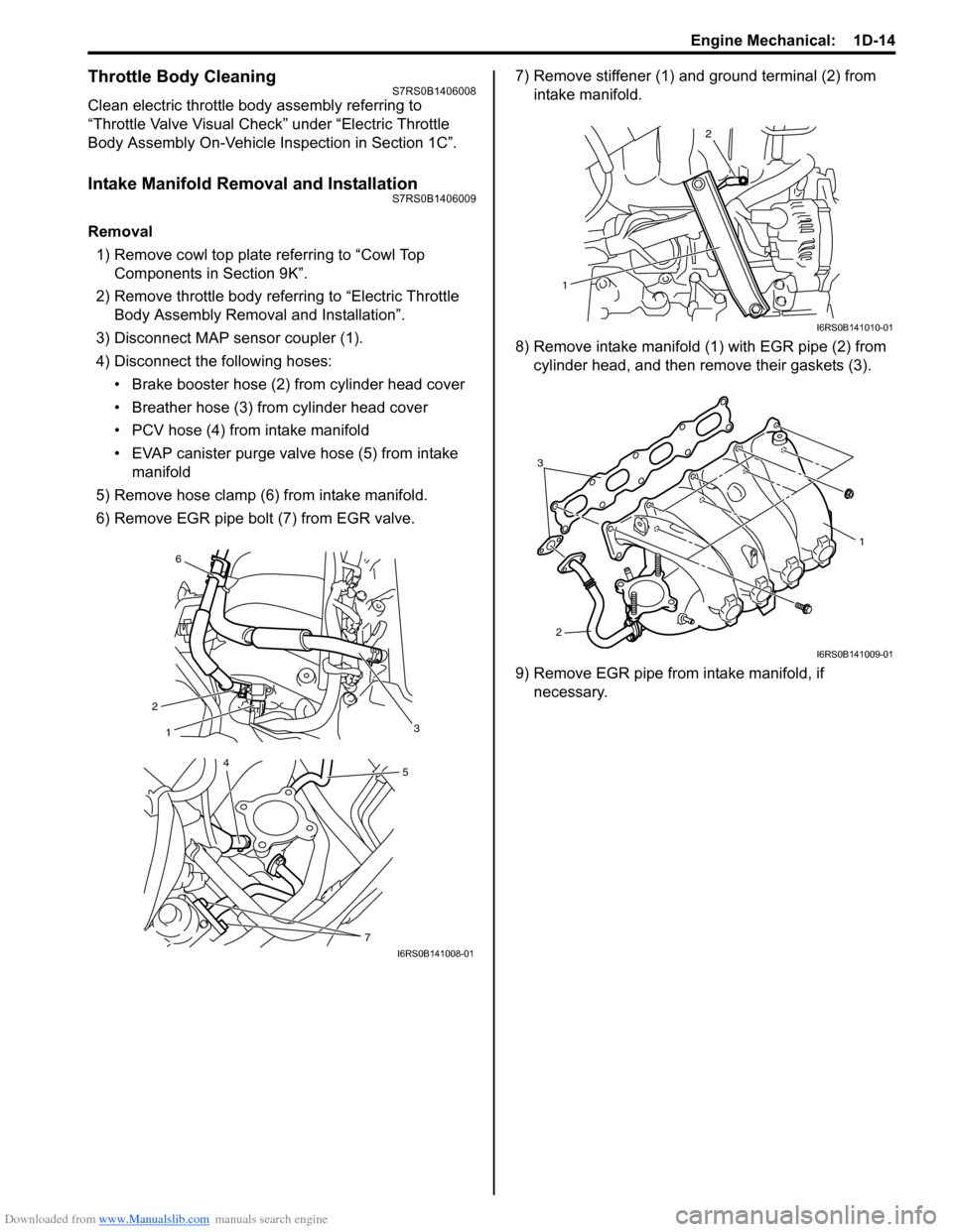
3) Disconnect MAP sensor coupler (1).
4) Disconnect the following hoses: • Brake booster hose (2) from cylinder head cover
• Breather hose (3) from cylinder head cover
• PCV hose (4) from intake manifold
• EVAP canister purge valve hose (5) from intake manifold
5) Remove hose clamp (6) from intake manifold.
6) Remove EGR pipe bolt (7) from EGR valve. 7) Remove stiffener (1) and ground terminal (2) from
intake manifold.
8) Remove intake manifold (1) with EGR pipe (2) from
cylinder head, and then remove their gaskets (3).
9) Remove EGR pipe from intake manifold, if necessary.
6
2 1
3
54
7I6RS0B141008-01
1
2
I6RS0B141010-01
3
2
1
I6RS0B141009-01
Page 377 of 1496
Downloaded from www.Manualslib.com manuals search engine Fuel System: 1G-2
Fuel Pump DescriptionS7RS0B1701003
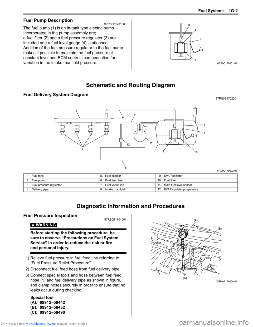
The fuel pump (1) is an in-tank type electric pump.
Incorporated in the pump assembly are;
a fuel filter (2) and a fuel pressure regulator (3) are
included and a fuel level gauge (4) is attached.
Addition of the fuel pressure regulator to the fuel pump
makes it possible to mainta in the fuel pressure at
constant level and ECM controls compensation for
variation in the intake manifold pressure.
Schematic and Routing Diagram
Fuel Delivery System DiagramS7RS0B1702001
Diagnostic Information and Procedures
Fuel Pressure InspectionS7RS0B1704001
WARNING!
Before starting the following procedure, be
sure to observe “Precautions on Fuel System
Service” in order to reduce the risk or fire
and personal injury.
1) Relieve fuel pressure in fuel feed line referring to
“Fuel Pressure Relief Procedure”.
2) Disconnect fuel feed hose from fuel delivery pipe.
3) Connect special tools and hose between fuel feed hose (1) and fuel delivery pipe as shown in figure,
and clamp hoses securely in order to ensure that no
leaks occur during checking.
Special tool
(A): 09912–58442
(B): 09912–58432
(C): 09912–58490
1
3
2
4
I6RS0C170001-01
4
6 7
8
12
2 3
11
10
5
1
9
I6RS0C170002-01
1. Fuel tank
5. Fuel injector9. EVAP canister
2. Fuel pump 6. Fuel feed line10. Fuel filter
3. Fuel pressure regulator 7. Fuel vapor line 11. Main fuel level sensor
4. Delivery pipe 8. Intake manifold12. EVAP canister purge valve
1
(C) (B)
(A)
I3RM0A170004-01
Page 383 of 1496
Downloaded from www.Manualslib.com manuals search engine Fuel System: 1G-8
Installation1) Install clamps to marked location on pipes. If clamp is deformed, its claw is bent or broken, replace it with
new one.
2) Install pipes with pipe clamps to vehicle.
3) Connect fuel hoses and pipes to each pipe referring to “Fuel Hose Disconnecting and Reconnecting”.
4) Connect negative cable at battery.
5) With engine OFF, turn igniti on switch to ON position
and check for fuel leaks.
Fuel Injector On-Vehicle InspectionS7RS0B1706007
1) Using sound scope (1) or such, check operating sound of injector (2) when engine is running or
cranking.
Cycle of operating sound should vary according to
engine speed.
If no sound or an unusual sound is heard, check
injector circuit (wire or coupler) or injector.
2) Disconnect connector (1) from injector, connect ohmmeter between terminals of injector and check
resistance.
If resistance is out of specification, replace.
Resistance of fuel injector
11.3 – 13.8 Ω at 20 °C, 68 °F
3) Connect connector to injector securely.
Fuel Injector Removal and InstallationS7RS0B1706008
WARNING!
Before starting the following procedure, be
sure to observe “Precautions on Fuel System
Service” in order to reduce the risk or fire
and personal injury.
Removal 1) Relieve fuel pressure according to “Fuel Pressure Relief Procedure”.
2) Disconnect negative cable at battery.
3) Disconnect MAF sensor connector, and detach EVAP canister purge valve.
4) Remove air cleaner assembly with air intake pipe.
5) Disconnect fuel injector couplers.
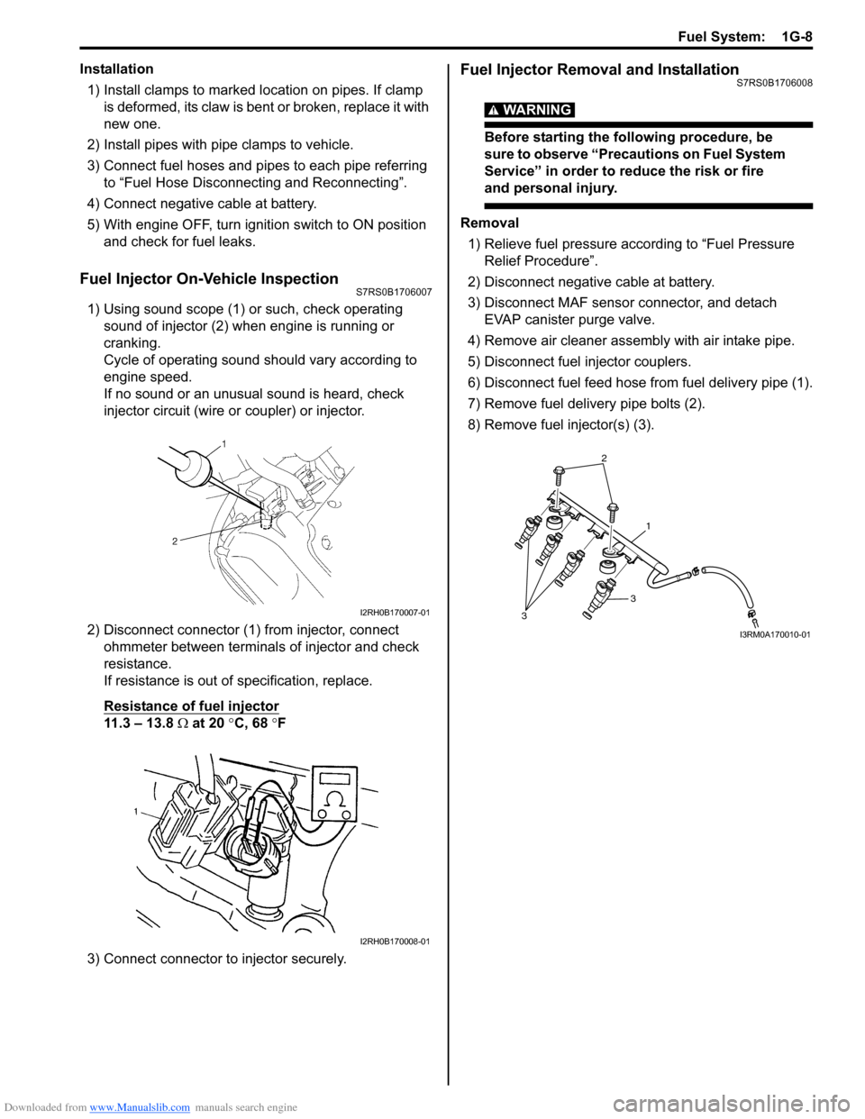
6) Disconnect fuel feed hose from fuel delivery pipe (1).
7) Remove fuel delivery pipe bolts (2).
8) Remove fuel injector(s) (3).
I2RH0B170007-01
I2RH0B170008-01
2
1
3
3
I3RM0A170010-01