bearing diameter SUZUKI SWIFT 2007 2.G Service User Guide
[x] Cancel search | Manufacturer: SUZUKI, Model Year: 2007, Model line: SWIFT, Model: SUZUKI SWIFT 2007 2.GPages: 1496, PDF Size: 34.44 MB
Page 349 of 1496
Downloaded from www.Manualslib.com manuals search engine Engine Mechanical: 1D-64
Honing or Reboring Cylinders1) When any cylinder needs reboring, all other cylinders must also be rebored at the same time.
2) Select oversized piston according to amount of cylinder wear.
Oversize piston specification
Oversize 0.50: 78.453 – 78.468 mm (3.0887 –
3.0893 in.)
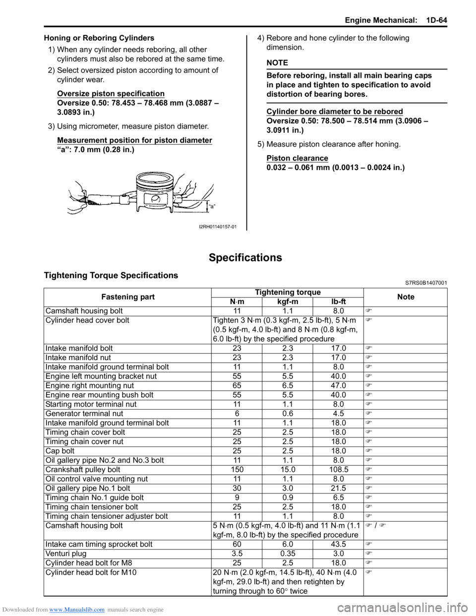
3) Using micrometer, measure piston diameter. Measurement position for piston diameter
“a”: 7.0 mm (0.28 in.) 4) Rebore and hone cylinder to the following
dimension.
NOTE
Before reboring, install all main bearing caps
in place and tighten to specification to avoid
distortion of bearing bores.
Cylinder bore diameter to be rebored
Oversize 0.50: 78.500 – 78.514 mm (3.0906 –
3.0911 in.)
5) Measure piston clearance after honing. Piston clearance
0.032 – 0.061 mm (0.0013 – 0.0024 in.)
Specifications
Tightening Torque SpecificationsS7RS0B1407001
I2RH01140157-01
Fastening part Tightening torque
Note
N ⋅mkgf-mlb-ft
Camshaft housing bolt 11 1.1 8.0 �)
Cylinder head cover bolt Tighten 3 N ⋅m (0.3 kgf-m, 2.5 lb-ft), 5 N ⋅m
(0.5 kgf-m, 4.0 lb-ft) and 8 N ⋅m (0.8 kgf-m,
6.0 lb-ft) by the specified procedure �)
Intake manifold bolt 23 2.3 17.0 �)
Intake manifold nut 23 2.3 17.0 �)
Intake manifold ground terminal bolt 11 1.1 8.0 �)
Engine left mounting bracket nut 55 5.5 40.0 �)
Engine right mounting nut 65 6.5 47.0 �)
Engine rear mounting bush bolt 55 5.5 40.0 �)
Starting motor terminal nut 11 1.1 8.0 �)
Generator terminal nut 6 0.6 4.5 �)
Intake manifold ground terminal bolt 11 1.1 18.0 �)
Timing chain cover bolt 25 2.5 18.0 �)
Timing chain cover nut 25 2.5 18.0 �)
Cap bolt 25 2.5 18.0 �)
Oil gallery pipe No.2 and No.3 bolt 11 1.1 8.0 �)
Crankshaft pulley bolt 150 15.0 108.5 �)
Oil control valve mounting nut 11 1.1 8.0 �)
Oil gallery pipe No.1 bolt 30 3.0 21.5 �)
Timing chain No.1 guide bolt 9 0.9 6.5 �)
Timing chain tensioner bolt 25 2.5 18.0 �)
Timing chain tensioner adjuster bolt 11 1.1 8.0 �)
Camshaft housing bolt 5 N ⋅m (0.5 kgf-m, 4.0 lb-ft) and 11 N ⋅m (1.1
kgf-m, 8.0 lb-ft) by the specified procedure �)
/ �)
Intake cam timing sprocket bolt 60 6.0 43.5 �)
Venturi plug 3.5 0.35 3.0 �)
Cylinder head bolt for M8 25 2.5 18.0 �)
Cylinder head bolt for M10 20 N ⋅m (2.0 kgf-m, 14.5 lb-ft), 40 N ⋅m (4.0
kgf-m, 29.0 lb-ft) and then retighten by
turning through to 60 ° twice �)
Page 469 of 1496
Downloaded from www.Manualslib.com manuals search engine Wheels and Tires: 2D-2
Lower than recommended pressure can cause:
• Tire squeal on turns
• Hard Steering
• Rapid and uneven wear on the edges of the tread
• Tire rim bruises and rupture
• Tire cord breakage
• High tire temperature
• Reduced handling
• High fuel consumption
Replacement Tires
When replacement is necessary, the original equipment
type tire should be used. Refer to the Tire Placard.
Replacement tires should be of the same size, load
range and construction as those originally on the vehicle.
Use of any other size or type tire may affect ride,
handling, speedometer / odometer calibration, vehicle
ground clearance and tire or snow chain clearance to the
body and chassis.
It is recommended that new tires be installed in pairs on
the same axle. If necessary to replace only one tire, it
should be paired with the tire having the most tread, to
equalize braking traction.
WARNING!
Do not mix different types of tires on the
same vehicle such as radial, bias and bias-
belted tires except in emergencies, because
handling may be seriously affected and may
result in loss of control.
The metric term for tire infl ation pressure is the kilo
pascal (kPa). Tire pressures is usually printed in both
kPa and kgf/cm
2 on the “Tire Placard”.
Metric tire gauges are available from tool suppliers.
The chart, shown the table, converts commonly used
inflation pressures from kPa to kgf/cm
2 and psi.
Wheels DescriptionS7RS0B2401002
Wheel Maintenance
Wheel repairs that use welding, heating, or peening are
not approved. All damaged wheels should be replaced.
Replacement Wheels
Wheels must be replaced if they are bent, dented, have
excessive lateral or radial runout, air leak through welds,
have elongated bolt holes, if lug wheel bolts won’t stay
tight, or if they are heavily rusted. Wheels with greater
runout than shown in the following may cause
objectional vibrations.
Replacement wheels must be equivalent to the original
equipment wheels in load capacity, diameter, rim with
offset and mounting configuration. A wheel of improper
size or type may affect wheel and bearing life, brake
cooling, speedometer / odometer calibration, vehicle
ground clearance and tire clearance to body and
chassis.
How to Measure Wheel Runout
To measure the wheel runout, it is necessary to use an
accurate dial indicator. The tire may be on or off the
wheel. The wheel should be installed to the wheel
balancer of the like for proper measurement.
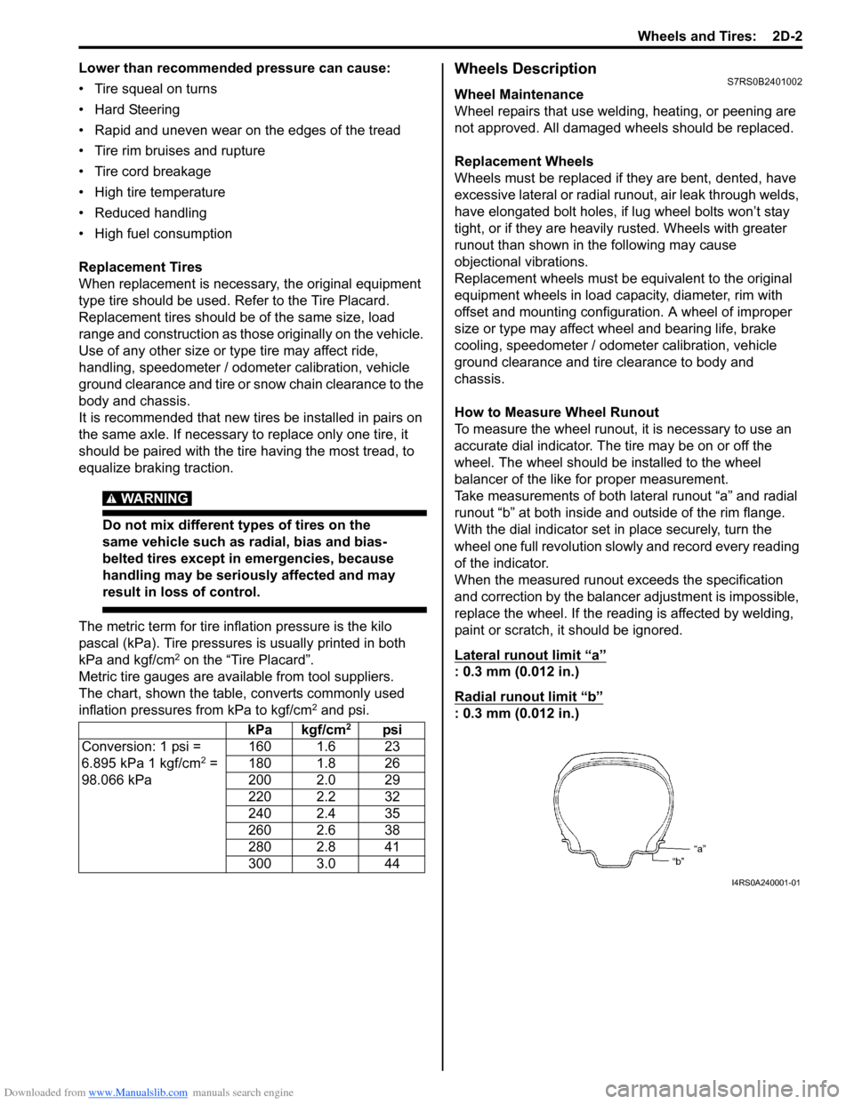
Take measurements of both lateral runout “a” and radial
runout “b” at both inside an d outside of the rim flange.
With the dial indicator set in place securely, turn the
wheel one full revolution slowly and record every reading
of the indicator.
When the measured runout exceeds the specification
and correction by the balancer adjustment is impossible,
replace the wheel. If the reading is affected by welding,
paint or scratch, it should be ignored.
Lateral runout limit “a”
: 0.3 mm (0.012 in.)
Radial runout limit “b”
: 0.3 mm (0.012 in.)
kPa kgf/cm2psi
Conversion: 1 psi =
6.895 kPa 1 kgf/cm
2 =
98.066 kPa 160 1.6 23
180 1.8 26
200 2.0 29
220 2.2 32
240 2.4 35
260 2.6 38
280 2.8 41
300 3.0 44
I4RS0A240001-01
Page 764 of 1496
Downloaded from www.Manualslib.com manuals search engine 5A-120 Automatic Transmission/Transaxle:
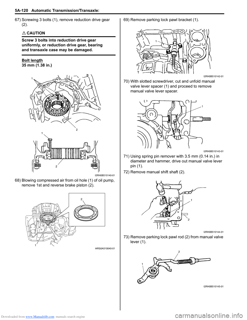
67) Screwing 3 bolts (1), remove reduction drive gear (2).
CAUTION!
Screw 3 bolts into reduction drive gear
uniformly, or reduction drive gear, bearing
and transaxle case may be damaged.
Bolt length
35 mm (1.38 in.)
68) Blowing compressed air from oil hole (1) of oil pump,
remove 1st and reverse brake piston (2). 69) Remove parking lock pawl bracket (1).
70) With slotted screwdriver, cut and unfold manual
valve lever spacer (1) and proceed to remove
manual valve lever spacer.
71) Using spring pin remover with 3.5 mm (0.14 in.) in diameter and hammer, drive out manual valve lever
pin (1).
72) Remove manual shift shaft (2).
73) Remove parking lock pawl rod (2) from manual valve lever (1).
I2RH0B510140-01
1 2I4RS0A510040-01
I2RH0B510142-01
I2RH0B510143-01
I2RH0B510144-01
I2RH0B510145-01
Page 794 of 1496
Downloaded from www.Manualslib.com manuals search engine 5A-150 Automatic Transmission/Transaxle:
Automatic Transaxle Unit AssemblyS7RS0B5106060
CAUTION!
• Automatic transaxle consists of highly precise parts. As even flaw in small part
may cause oil leakage or decrease in
function, check each part carefully before
installation.
• Clean all parts with compressed air. Never use wiping cloths or rags.
• Before assembling new clutch or brake discs, soak them in automatic transaxle
fluid for at least 2 hours.
• Be sure to use new gaskets and O-rings.
• Lubricate O-rings with automatic transaxle
fluid.
• Apply automatic transaxle fluid on sliding or rotating surfaces of the parts before
assembly.
• Use Suzuki Super Grease “C” to retain parts in place.
• Be sure to install thrust bearings and races in correct direction and position.
• Make sure that snap ring ends are not aligned with one of cut outs and are
installed in groove correctly.
• Do not use adhesive cements on gaskets and similar parts.
• Be sure to torque each bolt and nut to specification.
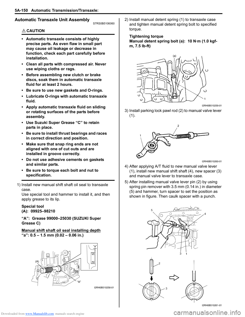
1) Install new manual shift sh aft oil seal to transaxle
case.
Use special tool and hammer to install it, and then
apply grease to its lip.
Special tool
(A): 09925–98210
“A”: Grease 99000–25030 (SUZUKI Super
Grease C)
Manual shift shaft oil seal installing depth
“a”: 0.5 – 1.5 mm (0.02 – 0.06 in.) 2) Install manual detent spring (1) to transaxle case
and tighten manual detent spring bolt to specified
torque.
Tightening torque
Manual detent spring bolt (a): 10 N·m (1.0 kgf-
m, 7.5 lb-ft)
3) Install parking lock pawl ro d (2) to manual valve lever
(1).
4) After applying A/T fluid to new manual valve lever (1), install new manual shift shaft (4), new spacer (3)
and manual valve lever to transaxle case.
5) After installing manual valve lever pin (2) by using spring pin remover with 3.5 mm (0.14 in.) in diameter
(5) and hammer, turn spacer to set the position as
shown in figure. Then caulk spacer with a punch.
“a”
(A)
“A”
I2RH0B510258-01
I2RH0B510259-01
I2RH0B510260-01
I2RH0B510261-01
Page 801 of 1496
Downloaded from www.Manualslib.com manuals search engine Automatic Transmission/Transaxle: 5A-157
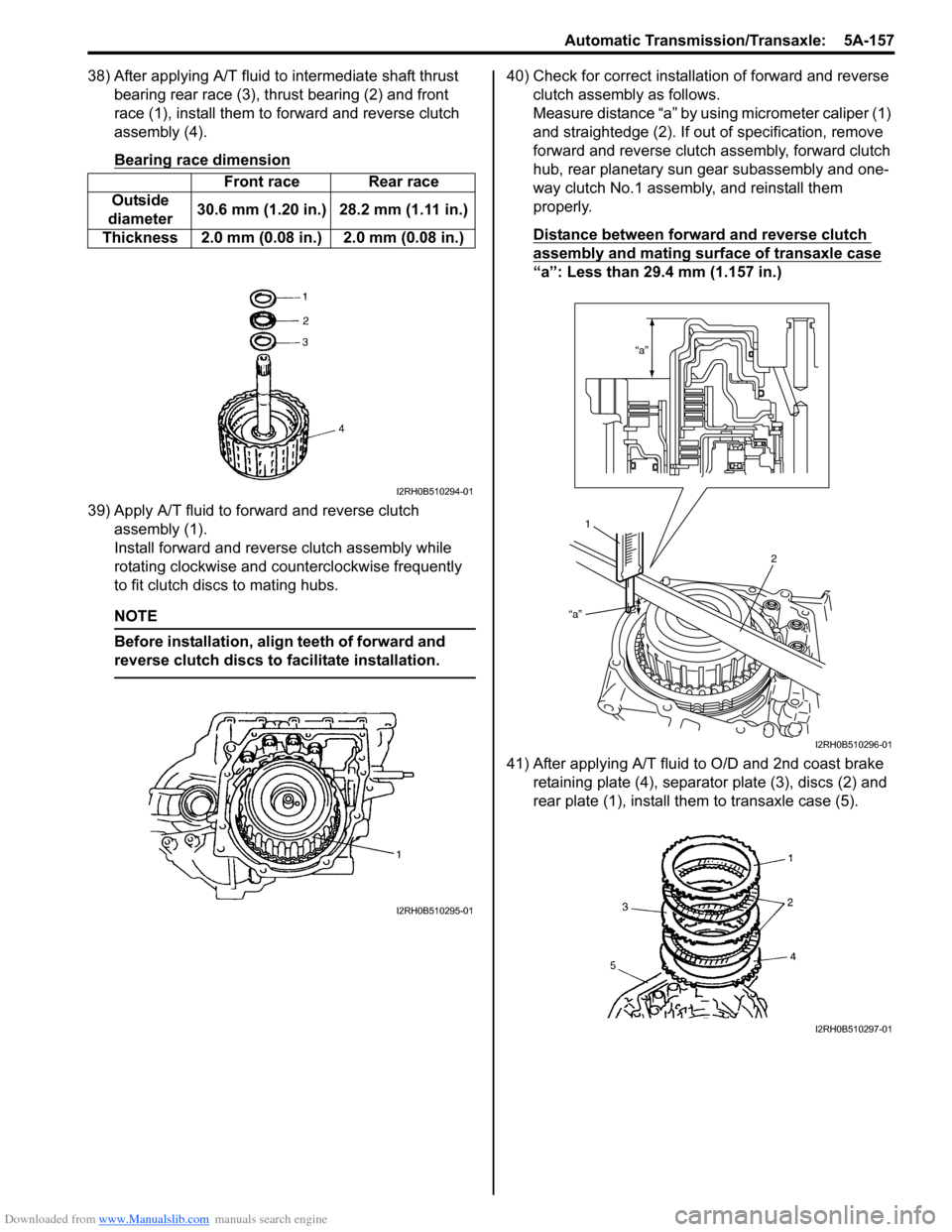
38) After applying A/T fluid to intermediate shaft thrust bearing rear race (3), thrust bearing (2) and front
race (1), install them to forward and reverse clutch
assembly (4).
Bearing race dimension
39) Apply A/T fluid to forward and reverse clutch assembly (1).
Install forward and revers e clutch assembly while
rotating clockwise and co unterclockwise frequently
to fit clutch discs to mating hubs.
NOTE
Before installation, align teeth of forward and
reverse clutch discs to facilitate installation.
40) Check for correct installation of forward and reverse clutch assembly as follows.
Measure distance “a” by using micrometer caliper (1)
and straightedge (2). If out of specification, remove
forward and reverse clutch assembly, forward clutch
hub, rear planetary sun gear subassembly and one-
way clutch No.1 assemb ly, and reinstall them
properly.
Distance between forward and reverse clutch
assembly and mating surface of transaxle case
“a”: Less than 29.4 mm (1.157 in.)
41) After applying A/T fluid to O/D and 2nd coast brake retaining plate (4), separator plate (3), discs (2) and
rear plate (1), install th em to transaxle case (5).
Front race Rear race
Outside
diameter 30.6 mm (1.20 in.) 28.2 mm (1.11 in.)
Thickness 2.0 mm (0.08 in.) 2.0 mm (0.08 in.)
I2RH0B510294-01
I2RH0B510295-01
“a”
“a”
1 2
I2RH0B510296-01
I2RH0B510297-01
Page 802 of 1496
Downloaded from www.Manualslib.com manuals search engine 5A-158 Automatic Transmission/Transaxle:
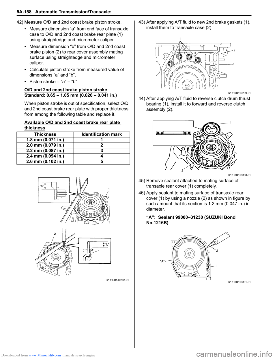
42) Measure O/D and 2nd coast brake piston stroke.• Measure dimension “a” from end face of transaxle case to O/D and 2nd coast brake rear plate (1)
using straightedge and micrometer caliper.
• Measure dimension “b” from O/D and 2nd coast brake piston (2) to rear cover assembly mating
surface using straightedge and micrometer
caliper.
• Calculate piston stroke from measured value of dimensions “a” and “b”.
• Piston stroke = “a” – “b”
O/D and 2nd coast brake piston stroke
Standard: 0.65 – 1.05 mm (0.026 – 0.041 in.)
When piston stroke is out of specification, select O/D
and 2nd coast brake rear plate with proper thickness
from among the following table and replace it.
Available O/D and 2nd coast brake rear plate
thickness
43) After applying A/T fluid to new 2nd brake gaskets (1), install them to transaxle case (2).
44) After applying A/T fluid to reverse clutch drum thrust bearing (1), install it to forward and reverse clutch
assembly (2).
45) Remove sealant attached to mating surface of transaxle rear cover (1) completely.
46) Apply sealant to mating surface of transaxle rear cover (1) by using a nozzle (2) as shown in figure by
such amount that its section is 1.2 mm (0.047 in.) in
diameter.
“A”: Sealant 99000–31230 (SUZUKI Bond
No.1216B)
Thickness Identification mark
1.8 mm (0.071 in.) 1
2.0 mm (0.079 in.) 2
2.2 mm (0.087 in.) 3
2.4 mm (0.094 in.) 4
2.6 mm (0.102 in.) 5
I2RH0B510298-01
I2RH0B510299-01
I2RH0B510300-01
“A” 2
1
I2RH0B510301-01
Page 805 of 1496
Downloaded from www.Manualslib.com manuals search engine Automatic Transmission/Transaxle: 5A-161
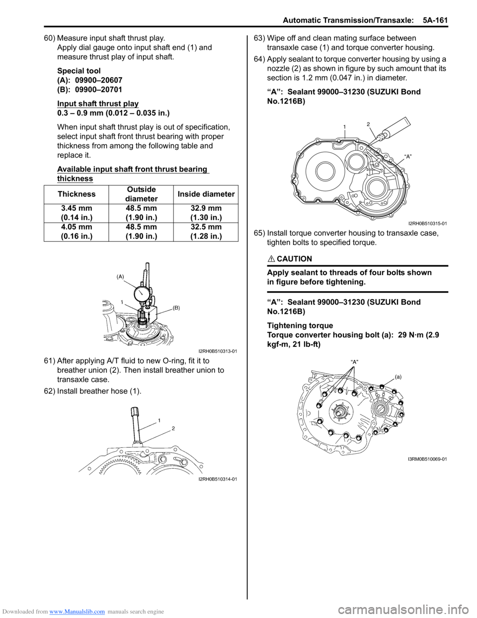
60) Measure input shaft thrust play.Apply dial gauge onto input shaft end (1) and
measure thrust play of input shaft.
Special tool
(A): 09900–20607
(B): 09900–20701
Input shaft thrust play
0.3 – 0.9 mm (0.012 – 0.035 in.)
When input shaft thrust play is out of specification,
select input shaft front th rust bearing with proper
thickness from among the following table and
replace it.
Available input shaft front thrust bearing
thickness
61) After applying A/T fluid to new O-ring, fit it to breather union (2). Then install breather union to
transaxle case.
62) Install breather hose (1). 63) Wipe off and clean mating surface between
transaxle case (1) and torque converter housing.
64) Apply sealant to torque converter housing by using a nozzle (2) as shown in figure by such amount that its
section is 1.2 mm (0.047 in.) in diameter.
“A”: Sealant 99000–31230 (SUZUKI Bond
No.1216B)
65) Install torque converter housing to transaxle case, tighten bolts to specified torque.
CAUTION!
Apply sealant to threads of four bolts shown
in figure before tightening.
“A”: Sealant 99000–31230 (SUZUKI Bond
No.1216B)
Tightening torque
Torque converter housing bolt (a): 29 N·m (2.9
kgf-m, 21 lb-ft)
Thickness
Outside
diameter Inside diameter
3.45 mm
(0.14 in.) 48.5 mm
(1.90 in.) 32.9 mm
(1.30 in.)
4.05 mm
(0.16 in.) 48.5 mm
(1.90 in.) 32.5 mm
(1.28 in.)
I2RH0B510313-01
I2RH0B510314-01
1 2
“A”
I2RH0B510315-01
I3RM0B510069-01
Page 830 of 1496
Downloaded from www.Manualslib.com manuals search engine 5B-16 Manual Transmission/Transaxle:
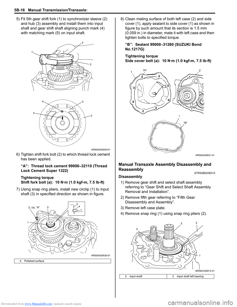
5) Fit 5th gear shift fork (1) to synchronizer sleeve (2) and hub (3) assembly and install them into input
shaft and gear shift shaft aligning punch mark (4)
with matching mark (5) on input shaft.
6) Tighten shift fork bolt (2) to which thread lock cement
has been applied.
“A”: Thread lock cement 99000–32110 (Thread
Lock Cement Super 1322)
Tightening torque
Shift fork bolt (a): 10 N·m (1.0 kgf-m, 7.5 lb-ft)
7) Using snap ring pliers, inst all new circlip (1) to input
shaft (3) in specified direction as shown in figure. 8) Clean mating surface of both left case (2) and side
cover (1), apply sealant to side cover (1) as shown in
figure by such amount t hat its section is 1.5 mm
(0.059 in.) in diameter, mate it with left case and then
tighten bolts to specified torque.
“B”: Sealant 99000–31260 (SUZUKI Bond
No.1217G)
Tightening torque
Side cover bolt (a): 10 N·m (1.0 kgf-m, 7.5 lb-ft)
Manual Transaxle Assembly Disassembly and
Reassembly
S7RS0B5206015
Disassembly
1) Remove gear shift and select shaft assembly referring to “Gear Shift an d Select Shaft Assembly
Removal and Installation”.
2) Remove fifth gear referring to “Fifth Gear Disassembly and Assembly”.
3) Remove left case plate.
4) Remove snap ring (1) using snap ring pliers (2).
4. Polished surface
I4RS0A520029-01
2, (a), “A”
1 33
4
1
I4RS0A520030-01
2. Input shaft 3. Input shaft left bearing
I4RS0A520031-01
1
2
2
3
I6RS0C520012-01
Page 853 of 1496
Downloaded from www.Manualslib.com manuals search engine Clutch: 5C-1
Transmission / Transaxle
Clutch
General Description
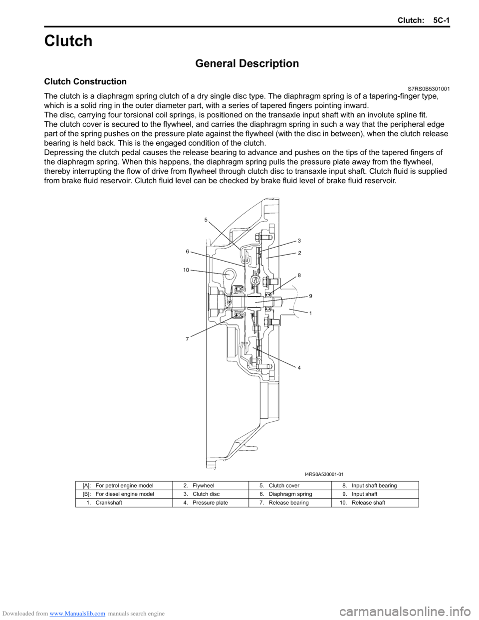
Clutch ConstructionS7RS0B5301001
The clutch is a diaphragm spring clutch of a dry single disc type. The diaphragm spring is of a tapering-finger type,
which is a solid ring in the outer diameter part, with a series of tapered fingers pointing inward.
The disc, carrying four torsional coil springs, is positione d on the transaxle input shaft with an involute spline fit.
The clutch cover is secured to the flywheel, and carries the diaphragm spring in such a way that the peripheral edge
part of the spring pushes on the pressure plate against the flywheel (with the disc in between), when the clutch release
bearing is held back. This is the engaged condition of the clutch.
Depressing the clutch pedal c auses the release bearing to advance and pushes on the tips of the tapered fingers of
the diaphragm spring. When this happens, the diaphragm sp ring pulls the pressure plate away from the flywheel,
thereby interrupting the flow of drive from flywheel through clutch disc to transaxle input shaft. Clutch fluid is supplied
from brake fluid reservoir. Clutch fluid level can be checked by brake fluid level of brake fluid reservoir.
[A]: For petrol engine model2. Flywheel5. Clutch cover 8. Input shaft bearing
[B]: For diesel engine model 3. Clutch disc6. Diaphragm spring 9. Input shaft
1. Crankshaft 4. Pressure plate7. Release bearing 10. Release shaft
I4RS0A530001-01