bleeding brake system SUZUKI SWIFT 2007 2.G Service User Guide
[x] Cancel search | Manufacturer: SUZUKI, Model Year: 2007, Model line: SWIFT, Model: SUZUKI SWIFT 2007 2.GPages: 1496, PDF Size: 34.44 MB
Page 570 of 1496

Downloaded from www.Manualslib.com manuals search engine 4E-31 ABS:
2) Bleed air from brake system referring to “Air Bleeding of Brake System in Section 4A”.
3) Check each installed part for fluid leakage and perform “ABS Hydraulic Un it Operation Check”.
NOTE
For new ABS hydraulic unit / control module
assembly, if “ABS Hydraulic Unit Operation
Check” has not been performed, ABS
warning light may flash when ignition switch
is turned ON position.
Accordingly preform “ABS Hydraulic Unit
Operation Check” to stop flashing of ABS
warning light.
Front / Rear Wheel Speed Sensor On-Vehicle
Inspection
S7RS0B4506005
Output Voltage Inspection
1) Disconnect negative cable from battery.
2) Hoist vehicle a little.
3) Disconnect wheel speed sensor connector.
4) Disconnect wheel speed grommet from vehicle body.
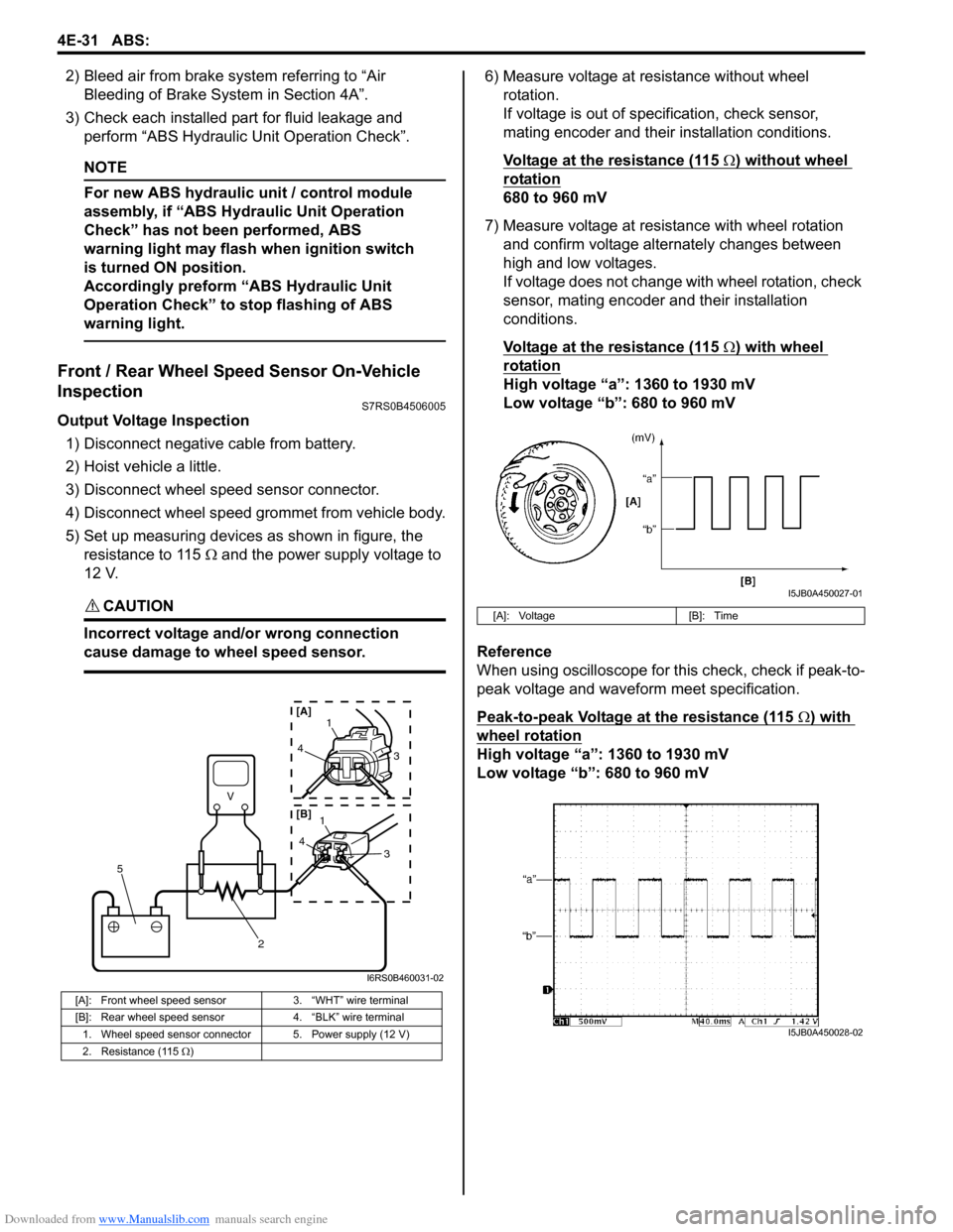
5) Set up measuring devices as shown in figure, the resistance to 115 Ω and the power supply voltage to
12 V.
CAUTION!
Incorrect voltage and/or wrong connection
cause damage to wheel speed sensor.
6) Measure voltage at resistance without wheel rotation.
If voltage is out of specification, check sensor,
mating encoder and their installation conditions.
Voltage at the resistance (115
Ω) without wheel
rotation
680 to 960 mV
7) Measure voltage at resistance with wheel rotation and confirm voltage alternately changes between
high and low voltages.
If voltage does not change with wheel rotation, check
sensor, mating encoder and their installation
conditions.
Voltage at the resistance (115
Ω) with wheel
rotation
High voltage “a”: 1360 to 1930 mV
Low voltage “b”: 680 to 960 mV
Reference
When using oscilloscope for this check, check if peak-to-
peak voltage and waveform meet specification.
Peak-to-peak Voltage at the resistance (115
Ω) with
wheel rotation
High voltage “a”: 1360 to 1930 mV
Low voltage “b”: 680 to 960 mV
[A]: Front wheel speed sensor 3. “WHT” wire terminal
[B]: Rear wheel speed sensor 4. “BLK” wire terminal
1. Wheel speed sensor connector 5. Power supply (12 V)
2. Resistance (115 Ω )
V
2
5
41
3
43
1
[A]
[B]
I6RS0B460031-02
[A]: Voltage [B]: Time
I5JB0A450027-01
I5JB0A450028-02
Page 631 of 1496

Downloaded from www.Manualslib.com manuals search engine Electronic Stability Program: 4F-57
3) Remove front brake pipe referring to “Front Brake Hose / Pipe Removal and In stallation in Section 4A”.
4) Remove ESP ® hydraulic unit / control module with
bracket from vehicle by removing bracket bolts.
5) Remove bolt (4) and pull out ESP ® hydraulic unit /
control module assembly (1) from bracket (3) using
flat end rod or the like (2).
Installation 1) Install hydraulic unit / co ntrol module assembly and
by reversing removal procedure.
Tightening torque
Brake pipe flare nut: 16 N·m (1.6 kgf-m, 11.5 lb-
ft)
ESP ® hydraulic unit / control module assembly
bolt: 9 N·m (0.9 kgf-m, 6.5 lb-ft)
ESP ® hydraulic unit / control module assembly
bracket bolt: 25 N·m (2.5 kgf-m, 18.0 lb-ft)
2) Bleed air from brake system referring to “Air Bleeding of Brake System in Section 4A”.
3) Check each installed part for fluid leakage.
4) Connect SUZUKI Scan Tool.
5) Turn ignition switch to ON position. And SLIP indicator lamp flush. (Other than replace with new
one) If other than SLIP indicator lamp light, check
DTC and repair it.
6) Turn ignition switch to ON position. And ESP®
warning lamp, SLIP indicator lamp, ESP ® OFF
lamp, Brake warning lamp lights and ABS warning
lamp flush. (Replace new one)
7) Check DTC.
NOTE
If any DTC(s) other than C1075, C1076 or
C1078 are detected, sensor calibration can
not be completed. Repair the detected it(s)
first.
8) Perform “Sensor Calibration”.
9) Perform “ESP ® Hydraulic Unit Operation Check”.
10) Turn ignition switch to OFF position once and then
ON position. In this state, make sure that indicator
light and warning light turns off.
11) Check DTC(s) are not stored in hydraulic unit / control module.
Front / Rear Wheel Speed Sensor On-Vehicle
Inspection
S7RS0B4606028
CAUTION!
Incorrect voltage and/or wrong connection
cause damage to wheel speed sensor.
Output Voltage Inspection
1) Disconnect negative (–) cable from battery.
2) Hoist vehicle a little.
3) Disconnect wheel speed sensor connector.
4) Disconnect wheel speed grommet from vehicle body.
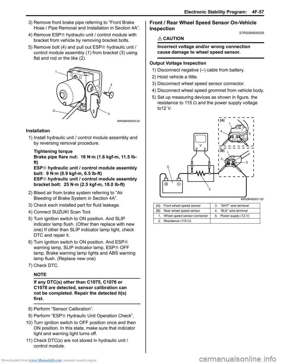
5) Set up measuring devices as shown in figure, the resistance to 115 Ω and the power supply voltage
to12 V.
4
1
2 3
I6RS0B460030-02
[A]: Front wheel speed sensor 3. “WHT” wire terminal
[B]: Rear wheel speed sensor 4. “BLK” wire terminal
1. Wheel speed sensor connector 5. Power supply (12 V)
2. Resistance (115 Ω)
V
2
5
4 1
3
43
1
[A]
[B]
I6RS0B460031-02
Page 636 of 1496

Downloaded from www.Manualslib.com manuals search engine 4F-62 Electronic Stability Program:
4) Turn ignition switch to ON position and select menu “DATA LIST” mode of SUZUKI scan tool. Refer to
scan tool operator's manual for further derails.
5) When brake pedal is released, check “Master Cyl Press” under “DATA LIST” of SUZUKI scan tool.
If pressure is out of specification, replace ESP ®
hydraulic unit / cont rol module assembly.
Master cylinder pressure specification
Brake pedal released: 0 ± 0.8 MPa (0 ± 8 kg/cm2, 0
± 113 psi)
6) Hoist vehicle and remove right-side front wheel.
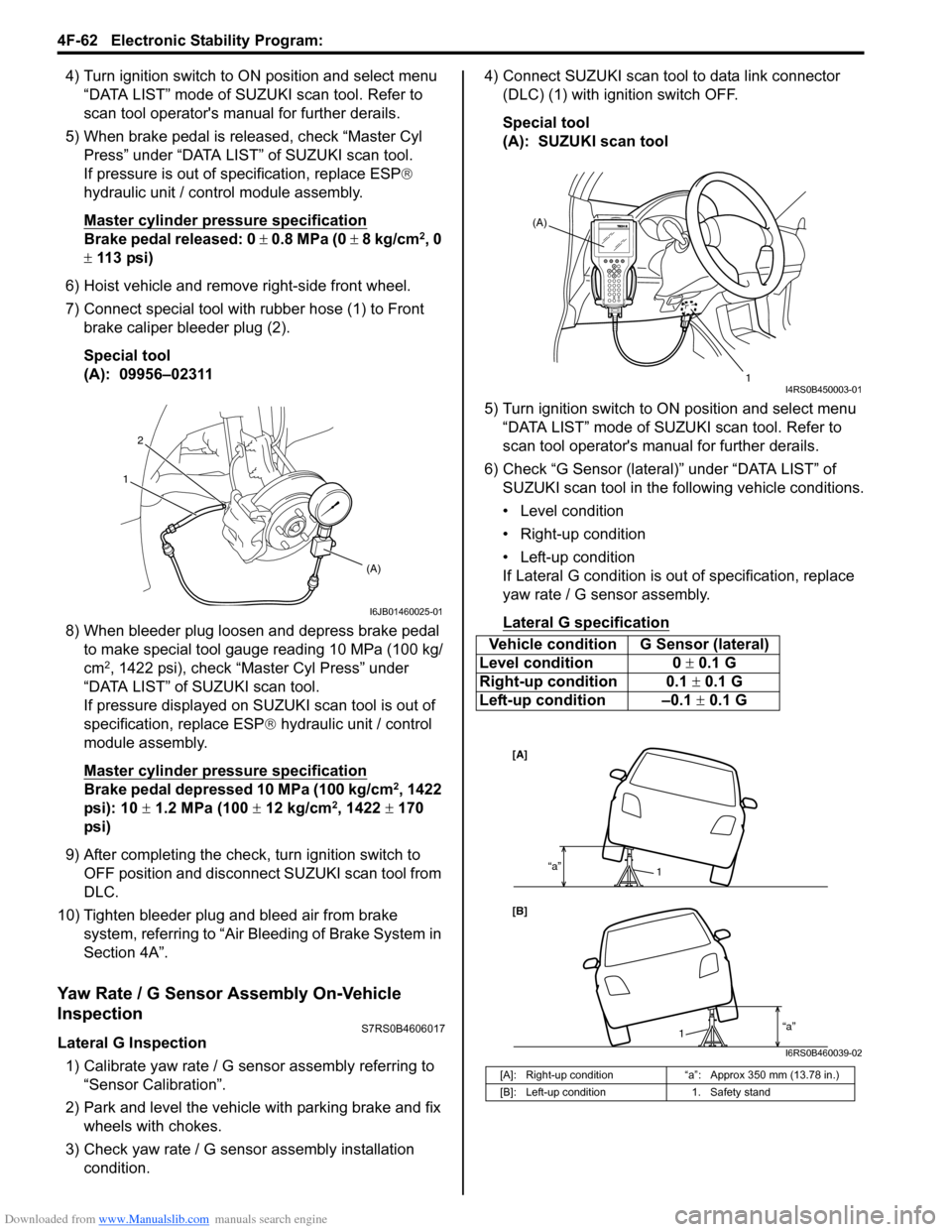
7) Connect special tool with rubber hose (1) to Front brake caliper bleeder plug (2).
Special tool
(A): 09956–02311
8) When bleeder plug loosen and depress brake pedal to make special tool gauge reading 10 MPa (100 kg/
cm
2, 1422 psi), check “Master Cyl Press” under
“DATA LIST” of SUZUKI scan tool.
If pressure displayed on SUZUKI scan tool is out of
specification, replace ESP ® hydraulic unit / control
module assembly.
Master cylinder pressure specification
Brake pedal depressed 10 MPa (100 kg/cm2, 1422
psi): 10 ± 1.2 MPa (100 ± 12 kg/cm2, 1422 ± 170
psi)
9) After completing the check, turn ignition switch to
OFF position and disconnect SUZUKI scan tool from
DLC.
10) Tighten bleeder plug and bleed air from brake system, referring to “Air Bleeding of Brake System in
Section 4A”.
Yaw Rate / G Sensor Assembly On-Vehicle
Inspection
S7RS0B4606017
Lateral G Inspection
1) Calibrate yaw rate / G sens or assembly referring to
“Sensor Calibration”.
2) Park and level the vehicle with parking brake and fix wheels with chokes.
3) Check yaw rate / G sensor assembly installation
condition. 4) Connect SUZUKI scan tool to data link connector
(DLC) (1) with ignition switch OFF.
Special tool
(A): SUZUKI scan tool
5) Turn ignition switch to ON position and select menu “DATA LIST” mode of SUZUKI scan tool. Refer to
scan tool operator's manual for further derails.
6) Check “G Sensor (lateral)” under “DATA LIST” of SUZUKI scan tool in the following vehicle conditions.
• Level condition
• Right-up condition
• Left-up condition
If Lateral G condition is ou t of specification, replace
yaw rate / G sensor assembly.
Lateral G sp ecification
2
(A)
1
I6JB01460025-01
Vehicle condition G Sensor (lateral)
Level condition 0 ± 0.1 G
Right-up condition 0.1 ± 0.1 G
Left-up condition –0.1 ± 0.1 G
[A]: Right-up condition “a”: Approx 350 mm (13.78 in.)
[B]: Left-up condition 1. Safety stand
(A)
1
I4RS0B450003-01
[A]
[B]“a”
1
“a”1
I6RS0B460039-02
Page 855 of 1496

Downloaded from www.Manualslib.com manuals search engine Clutch: 5C-3
Clutch Release Margin “C”1) Pull up parking brake fully and block wheels.
2) Start engine and keep engine at idle with neutral gear position.
3) Without clutch pedal (1) dep ressed, slightly push the
shift lever to re verse position until transaxle emits
gear contact noise. Do not shift the lever to reverse
position.
4) With emitting gear contact noise, be slow to depress clutch pedal (1), and at gear contact noise died
position (release point) stop depressing.
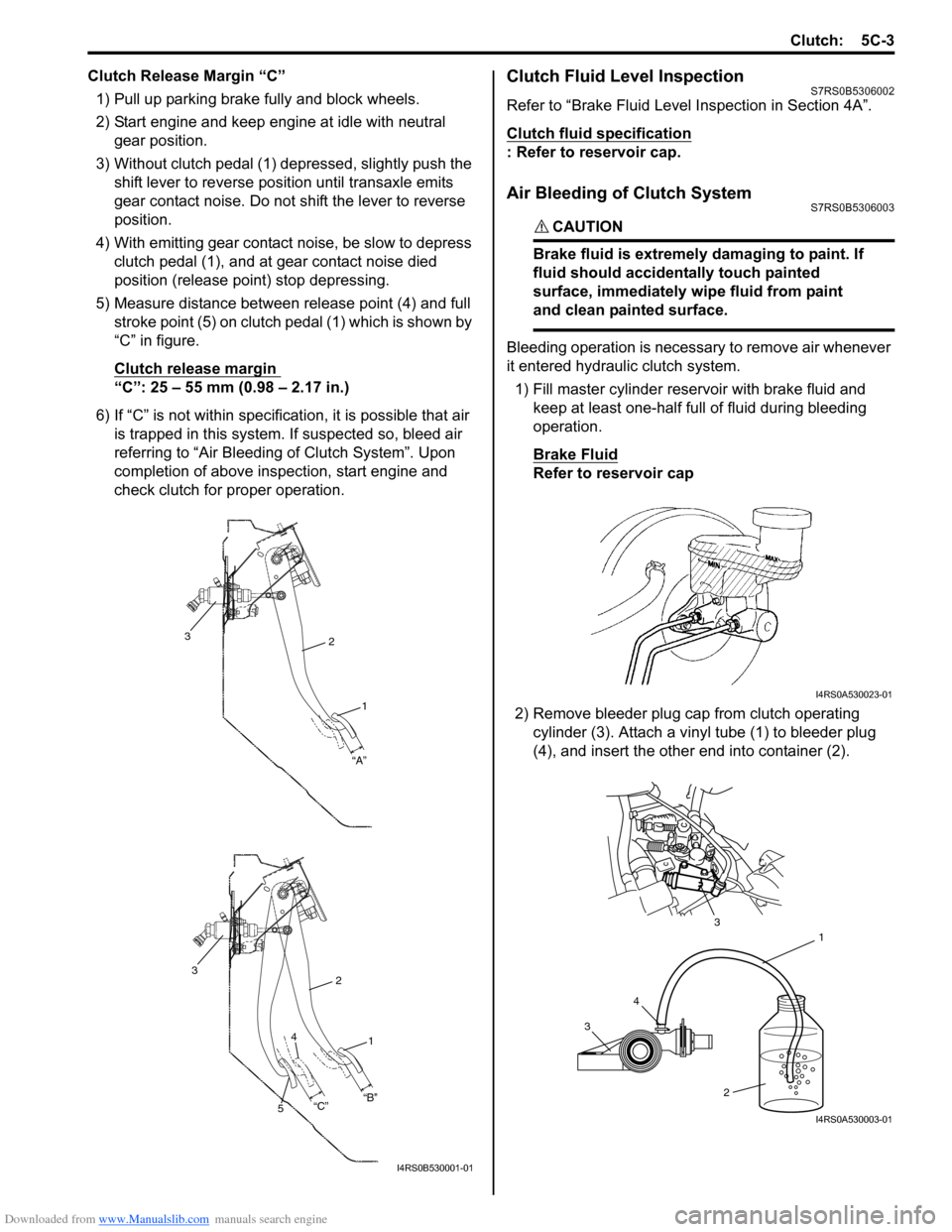
5) Measure distance between release point (4) and full stroke point (5) on clutch pedal (1) which is shown by
“C” in figure.
Clutch release margin
“C”: 25 – 55 mm (0.98 – 2.17 in.)
6) If “C” is not within specificat ion, it is possible that air
is trapped in this system. If suspected so, bleed air
referring to “Air Bleeding of Clutch System”. Upon
completion of above inspection, start engine and
check clutch for proper operation.
Clutch Fluid Level InspectionS7RS0B5306002
Refer to “Brake Fluid Level Inspection in Section 4A”.
Clutch fluid specification
: Refer to reservoir cap.
Air Bleeding of Clutch SystemS7RS0B5306003
CAUTION!
Brake fluid is extremely damaging to paint. If
fluid should accidentally touch painted
surface, immediately wipe fluid from paint
and clean painted surface.
Bleeding operation is necessary to remove air whenever
it entered hydraulic clutch system.
1) Fill master cylinder reservoir with brake fluid and keep at least one-half full of fluid during bleeding
operation.
Brake Fluid
Refer to reservoir cap
2) Remove bleeder plug cap from clutch operating cylinder (3). Attach a vinyl tube (1) to bleeder plug
(4), and insert the other end into container (2).
2
1
“A”
3
2
1
3
“B”
“C”
4
5
I4RS0B530001-01
I4RS0A530023-01
3 4 1
2
3
I4RS0A530003-01