fuel leakage SUZUKI SWIFT 2007 2.G Service User Guide
[x] Cancel search | Manufacturer: SUZUKI, Model Year: 2007, Model line: SWIFT, Model: SUZUKI SWIFT 2007 2.GPages: 1496, PDF Size: 34.44 MB
Page 147 of 1496
Downloaded from www.Manualslib.com manuals search engine Engine General Information and Diagnosis: 1A-97
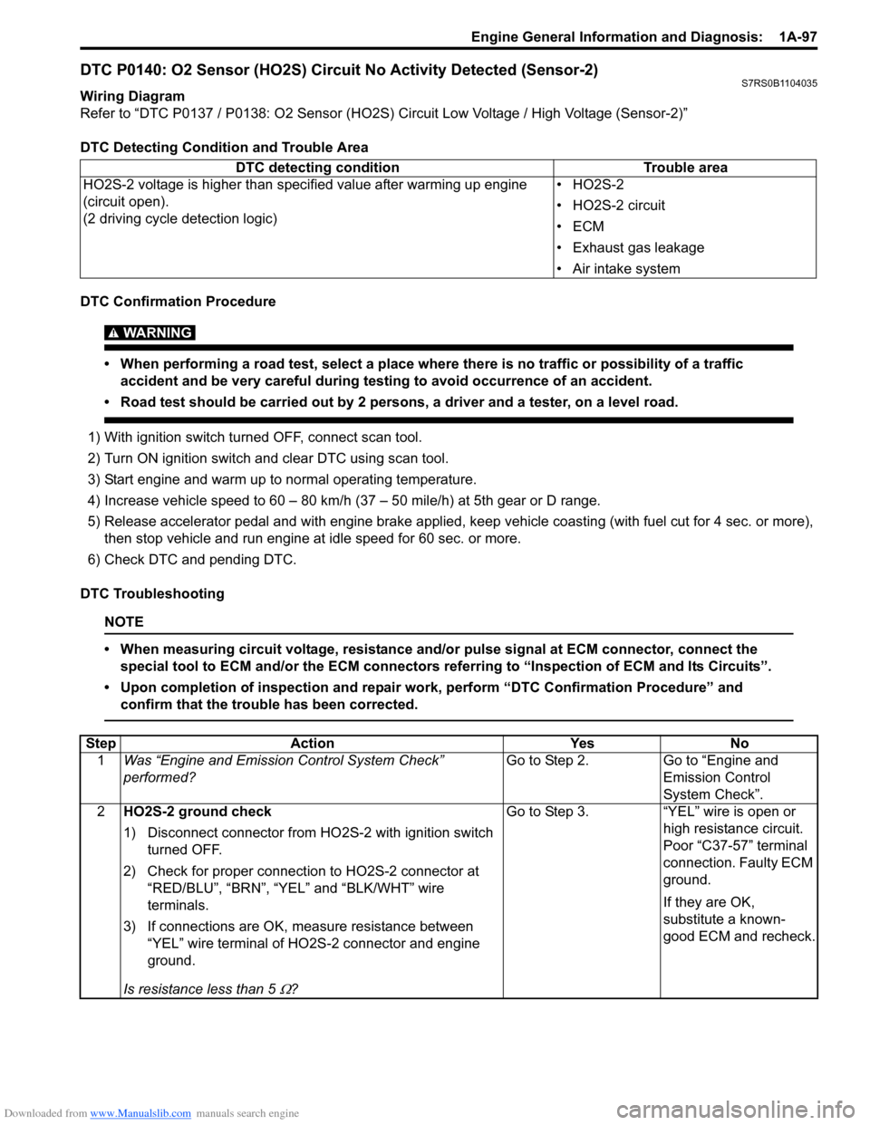
DTC P0140: O2 Sensor (HO2S) Circuit No Activity Detected (Sensor-2)S7RS0B1104035
Wiring Diagram
Refer to “DTC P0137 / P0138: O2 Sensor (HO2S) Circuit Low Voltage / High Voltage (Sensor-2)”
DTC Detecting Condition and Trouble Area
DTC Confirmation Procedure
WARNING!
• When performing a road test, select a place where there is no traffic or possibility of a traffic accident and be very careful during testing to avoid occurrence of an accident.
• Road test should be carried out by 2 persons, a driver and a tester, on a level road.
1) With ignition switch turned OFF, connect scan tool.
2) Turn ON ignition switch and clear DTC using scan tool.
3) Start engine and warm up to normal operating temperature.
4) Increase vehicle speed to 60 – 80 km/h (37 – 50 mile/h) at 5th gear or D range.
5) Release accelerator pedal and with engine brake applied, ke ep vehicle coasting (with fuel cut for 4 sec. or more),
then stop vehicle and run engine at idle speed for 60 sec. or more.
6) Check DTC and pending DTC.
DTC Troubleshooting
NOTE
• When measuring circuit voltage, resistance and/ or pulse signal at ECM connector, connect the
special tool to ECM and/or the ECM connectors re ferring to “Inspection of ECM and Its Circuits”.
• Upon completion of inspection and repair work, perform “DTC Confirmation Procedure” and confirm that the trouble has been corrected.
DTC detecting condition Trouble area
HO2S-2 voltage is higher than specified value after warming up engine
(circuit open).
(2 driving cycle detection logic) •HO2S-2
• HO2S-2 circuit
•ECM
• Exhaust gas leakage
• Air intake system
Step
Action YesNo
1 Was “Engine and Emission Control System Check”
performed? Go to Step 2.
Go to “Engine and
Emission Control
System Check”.
2 HO2S-2 ground check
1) Disconnect connector from HO 2S-2 with ignition switch
turned OFF.
2) Check for proper connection to HO2S-2 connector at “RED/BLU”, “BRN”, “YEL” and “BLK/WHT” wire
terminals.
3) If connections are OK, m easure resistance between
“YEL” wire terminal of HO2S-2 connector and engine
ground.
Is resistance less than 5
Ω? Go to Step 3. “YEL” wire is open or
high resistance circuit.
Poor “C37-57” terminal
connection. Faulty ECM
ground.
If they are OK,
substitute a known-
good ECM and recheck.
Page 148 of 1496
Downloaded from www.Manualslib.com manuals search engine 1A-98 Engine General Information and Diagnosis:
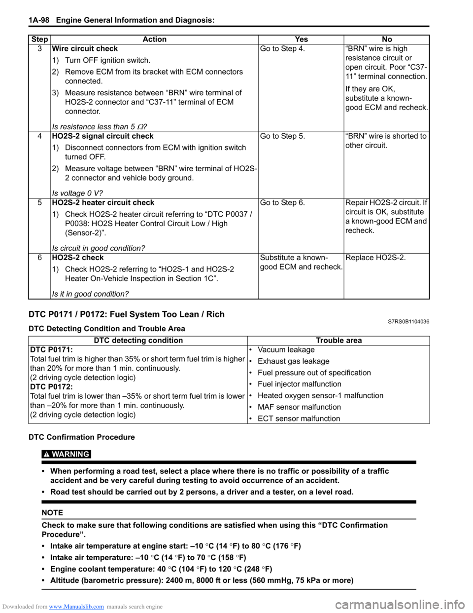
DTC P0171 / P0172: Fuel System Too Lean / RichS7RS0B1104036
DTC Detecting Condition and Trouble Area
DTC Confirmation Procedure
WARNING!
• When performing a road test, select a place where there is no traffic or possibility of a traffic accident and be very careful during testing to avoid occurrence of an accident.
• Road test should be carried out by 2 persons, a driver and a tester, on a level road.
NOTE
Check to make sure that following conditions ar e satisfied when using this “DTC Confirmation
Procedure”.
• Intake air temperature at engine start: –10 °C (14 ° F) to 80 °C (176 °F)
• Intake air temperature: –10 °C (14 °F) to 70 °C (158 °F)
• Engine coolant temperature: 40 °C (104 °F) to 120 °C (248 °F)
• Altitude (barometric pressure): 2400 m, 8000 ft or less (560 mmHg, 75 kPa or more)
3 Wire circuit check
1) Turn OFF ignition switch.
2) Remove ECM from its br acket with ECM connectors
connected.
3) Measure resistance between “BRN” wire terminal of HO2S-2 connector and “C37-11” terminal of ECM
connector.
Is resistance less than 5
Ω? Go to Step 4. “BRN” wire is high
resistance circuit or
open circuit. Poor “C37-
11” terminal connection.
If they are OK,
substitute a known-
good ECM and recheck.
4 HO2S-2 signal circuit check
1) Disconnect connectors from ECM with ignition switch
turned OFF.
2) Measure voltage between “BRN” wire terminal of HO2S- 2 connector and vehicle body ground.
Is voltage 0 V? Go to Step 5. “BRN” wire is shorted to
other circuit.
5 HO2S-2 heater circuit check
1) Check HO2S-2 heater circuit referring to “DTC P0037 /
P0038: HO2S Heater Control Circuit Low / High
(Sensor-2)”.
Is circuit in good condition? Go to Step 6. Repair HO2S-2 circuit. If
circuit is OK, substitute
a known-good ECM and
recheck.
6 HO2S-2 check
1) Check HO2S-2 referring to “HO2S-1 and HO2S-2
Heater On-Vehicle Inspection in Section 1C”.
Is it in good condition? Substitute a known-
good ECM and recheck.
Replace HO2S-2.
Step Action Yes No
DTC detecting condition
Trouble area
DTC P0171:
Total fuel trim is higher than 35% or short term fuel trim is higher
than 20% for more than 1 min. continuously.
(2 driving cycle detection logic)
DTC P0172:
Total fuel trim is lower than –35% or short term fuel trim is lower
than –20% for more than 1 min. continuously.
(2 driving cycle detection logic) • Vacuum leakage
• Exhaust gas leakage
• Fuel pressure out of specification
• Fuel injector malfunction
• Heated oxygen sensor-1 malfunction
• MAF sensor malfunction
• ECT sensor malfunction
Page 149 of 1496
Downloaded from www.Manualslib.com manuals search engine Engine General Information and Diagnosis: 1A-99
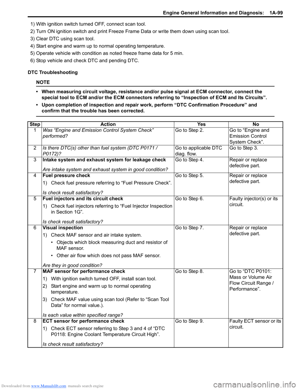
1) With ignition switch turned OFF, connect scan tool.
2) Turn ON ignition switch and print Freeze Frame Data or write them down using scan tool.
3) Clear DTC using scan tool.
4) Start engine and warm up to normal operating temperature.
5) Operate vehicle with condition as noted freeze frame data for 5 min.
6) Stop vehicle and check DTC and pending DTC.
DTC Troubleshooting
NOTE
• When measuring circuit voltage, resistance and/ or pulse signal at ECM connector, connect the
special tool to ECM and/or the ECM connectors re ferring to “Inspection of ECM and Its Circuits”.
• Upon completion of inspection and repair work, perform “DTC Confirmation Procedure” and confirm that the trouble has been corrected.
Step Action YesNo
1 Was “Engine and Emission Control System Check”
performed? Go to Step 2.
Go to “Engine and
Emission Control
System Check”.
2 Is there DTC(s) other than fuel system (DTC P0171 /
P0172)? Go to applicable DTC
diag. flow.Go to Step 3.
3 Intake system and exhaust system for leakage check
Are intake system and exhaust system in good condition? Go to Step 4.
Repair or replace
defective part.
4 Fuel pressure check
1) Check fuel pressure referring to “Fuel Pressure Check”.
Is check result satisfactory? Go to Step 5.
Repair or replace
defective part.
5 Fuel injectors and its circuit check
1) Check fuel injectors referring to “Fuel Injector Inspection
in Section 1G”.
Is check result satisfactory? Go to Step 6.
Faulty injector(s) or its
circuit.
6 Visual inspection
1) Check MAF sensor and air intake system.
• Objects which block measur ing duct and resistor of
MAF sensor.
• Other air flow which does not pass MAF sensor.
Are they in good condition? Go to Step 7.
Repair or replace
defective part.
7 MAF sensor for performance check
1) With ignition switch turn ed OFF, install scan tool.
2) Start engine and warm up to normal operating temperature.
3) Check MAF value using scan tool (Refer to “Scan Tool Data” for normal value.).
Is each value within specified range? Go to Step 8.
Go to “DTC P0101:
Mass or Volume Air
Flow Circuit Range /
Performance”.
8 ECT sensor for performance check
1) Check ECT sensor referring to Step 3 and 4 of “DTC
P0118: Engine Coolant Temperature Circuit High”.
Is check result satisfactory? Go to Step 9.
Faulty ECT sensor or its
circuit.
Page 254 of 1496
Downloaded from www.Manualslib.com manuals search engine 1A-204 Engine General Information and Diagnosis:
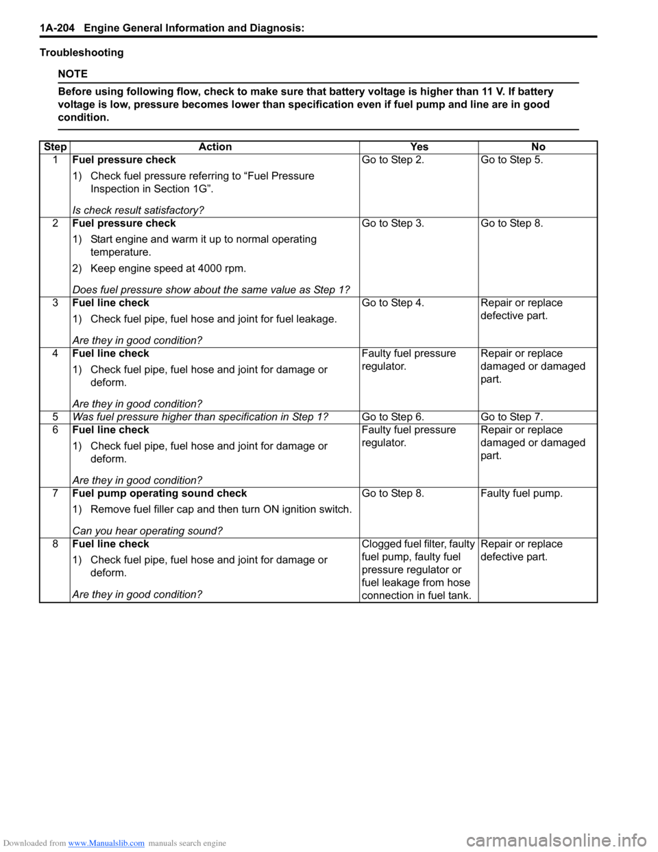
Troubleshooting
NOTE
Before using following flow, check to make sure that battery voltage is higher than 11 V. If battery
voltage is low, pressure becomes lower than specification even if fuel pump and line are in good
condition.
StepAction YesNo
1 Fuel pressure check
1) Check fuel pressure referring to “Fuel Pressure
Inspection in Section 1G”.
Is check result satisfactory? Go to Step 2.
Go to Step 5.
2 Fuel pressure check
1) Start engine and warm it up to normal operating
temperature.
2) Keep engine speed at 4000 rpm.
Does fuel pressure show about the same value as Step 1? Go to Step 3.
Go to Step 8.
3 Fuel line check
1) Check fuel pipe, fuel hose and joint for fuel leakage.
Are they in good condition? Go to Step 4.
Repair or replace
defective part.
4 Fuel line check
1) Check fuel pipe, fuel hose and joint for damage or
deform.
Are they in good condition? Faulty fuel pressure
regulator.
Repair or replace
damaged or damaged
part.
5 Was fuel pressure higher than specification in Step 1? Go to Step 6.Go to Step 7.
6 Fuel line check
1) Check fuel pipe, fuel hose and joint for damage or
deform.
Are they in good condition? Faulty fuel pressure
regulator.
Repair or replace
damaged or damaged
part.
7 Fuel pump operating sound check
1) Remove fuel filler cap and th en turn ON ignition switch.
Can you hear operating sound? Go to Step 8.
Faulty fuel pump.
8 Fuel line check
1) Check fuel pipe, fuel hose and joint for damage or
deform.
Are they in good condition? Clogged fuel filter, faulty
fuel pump, faulty fuel
pressure regulator or
fuel leakage from hose
connection in fuel tank.Repair or replace
defective part.
Page 270 of 1496
Downloaded from www.Manualslib.com manuals search engine 1B-3 Aux. Emission Control Devices:
Vacuum Passage InspectionS7RS0B1206003
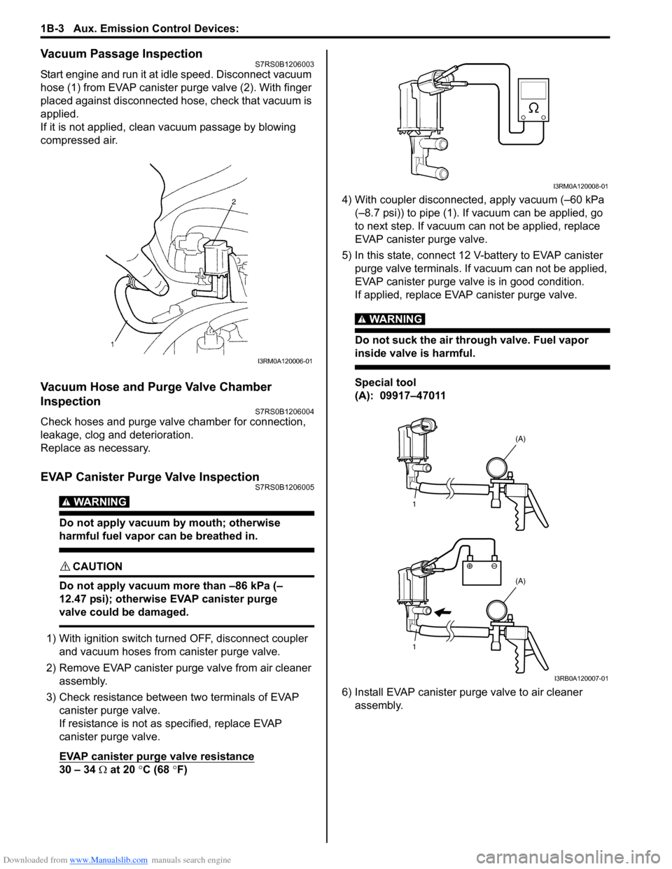
Start engine and run it at idle speed. Disconnect vacuum
hose (1) from EVAP canister purge valve (2). With finger
placed against disconnected hose, check that vacuum is
applied.
If it is not applied, clean vacuum passage by blowing
compressed air.
Vacuum Hose and Purge Valve Chamber
Inspection
S7RS0B1206004
Check hoses and purge valv e chamber for connection,
leakage, clog and deterioration.
Replace as necessary.
EVAP Canister Purge Valve InspectionS7RS0B1206005
WARNING!
Do not apply vacuum by mouth; otherwise
harmful fuel vapor can be breathed in.
CAUTION!
Do not apply vacuum more than –86 kPa (–
12.47 psi); otherwise EVAP canister purge
valve could be damaged.
1) With ignition switch turned OFF, disconnect coupler and vacuum hoses from canister purge valve.
2) Remove EVAP canister purge valve from air cleaner assembly.
3) Check resistance between two terminals of EVAP canister purge valve.
If resistance is not as specified, replace EVAP
canister purge valve.
EVAP canister purge valve resistance
30 – 34 Ω at 20 °C (68 °F) 4) With coupler disconnected, apply vacuum (–60 kPa
(–8.7 psi)) to pipe (1). If vacuum can be applied, go
to next step. If vacuum can not be applied, replace
EVAP canister purge valve.
5) In this state, connect 12 V-battery to EVAP canister purge valve terminals. If vacuum can not be applied,
EVAP canister purge valve is in good condition.
If applied, replace EVAP canister purge valve.
WARNING!
Do not suck the air through valve. Fuel vapor
inside valve is harmful.
Special tool
(A): 09917–47011
6) Install EVAP canister purge valve to air cleaner assembly.
I3RM0A120006-01
I3RM0A120008-01
1
1 (A)
(A)
I3RB0A120007-01
Page 271 of 1496
Downloaded from www.Manualslib.com manuals search engine Aux. Emission Control Devices: 1B-4
EVAP Canister InspectionS7RS0B1206006
WARNING!
DO NOT SUCK nozzles on EVAP canister.
Fuel vapor inside EVAP canister is harmful.
1) Check outside of EVAP canister visually.
2) Disconnect vacuum hoses from EVAP canister.
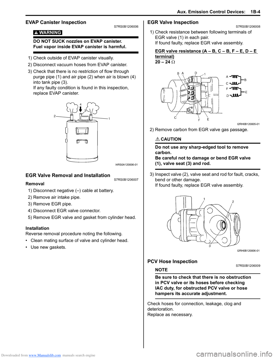
3) Check that there is no restriction of flow through purge pipe (1) and air pipe (2) when air is blown (4)
into tank pipe (3).
If any faulty condition is found in this inspection,
replace EVAP canister.
EGR Valve Removal and InstallationS7RS0B1206007
Removal
1) Disconnect negative (–) cable at battery.
2) Remove air intake pipe.
3) Remove EGR pipe.
4) Disconnect EGR valve connector.
5) Remove EGR valve and gasket from cylinder head.
Installation
Reverse removal procedure noting the following.
• Clean mating surface of valve and cylinder head.
• Use new gaskets.
EGR Valve InspectionS7RS0B1206008
1) Check resistance between following terminals of EGR valve (1) in each pair.
If found faulty, replace EGR valve assembly.
EGR valve resistance (A – B, C – B, F – E, D – E
terminal)
20 – 24 Ω
2) Remove carbon from EGR valve gas passage.
CAUTION!
Do not use any sharp-edged tool to remove
carbon.
Be careful not to damage or bend EGR valve
(1), valve seat (3) and rod.
3) Inspect valve (2), valve seat and rod for fault, cracks, bend or other damage.
If found faulty, replace EGR valve assembly.
PCV Hose InspectionS7RS0B1206009
NOTE
Be sure to check that there is no obstruction
in PCV valve or its hoses before checking
IAC duty, for obstructed PCV valve or hose
hampers its accurate adjustment.
Check hoses for connection, leakage, clog and
deterioration.
Replace as necessary.
I4RS0A120006-01
I2RH0B120005-01
I2RH0B120006-01
Page 290 of 1496
Downloaded from www.Manualslib.com manuals search engine 1D-5 Engine Mechanical:
11) Connect negative cable at battery.
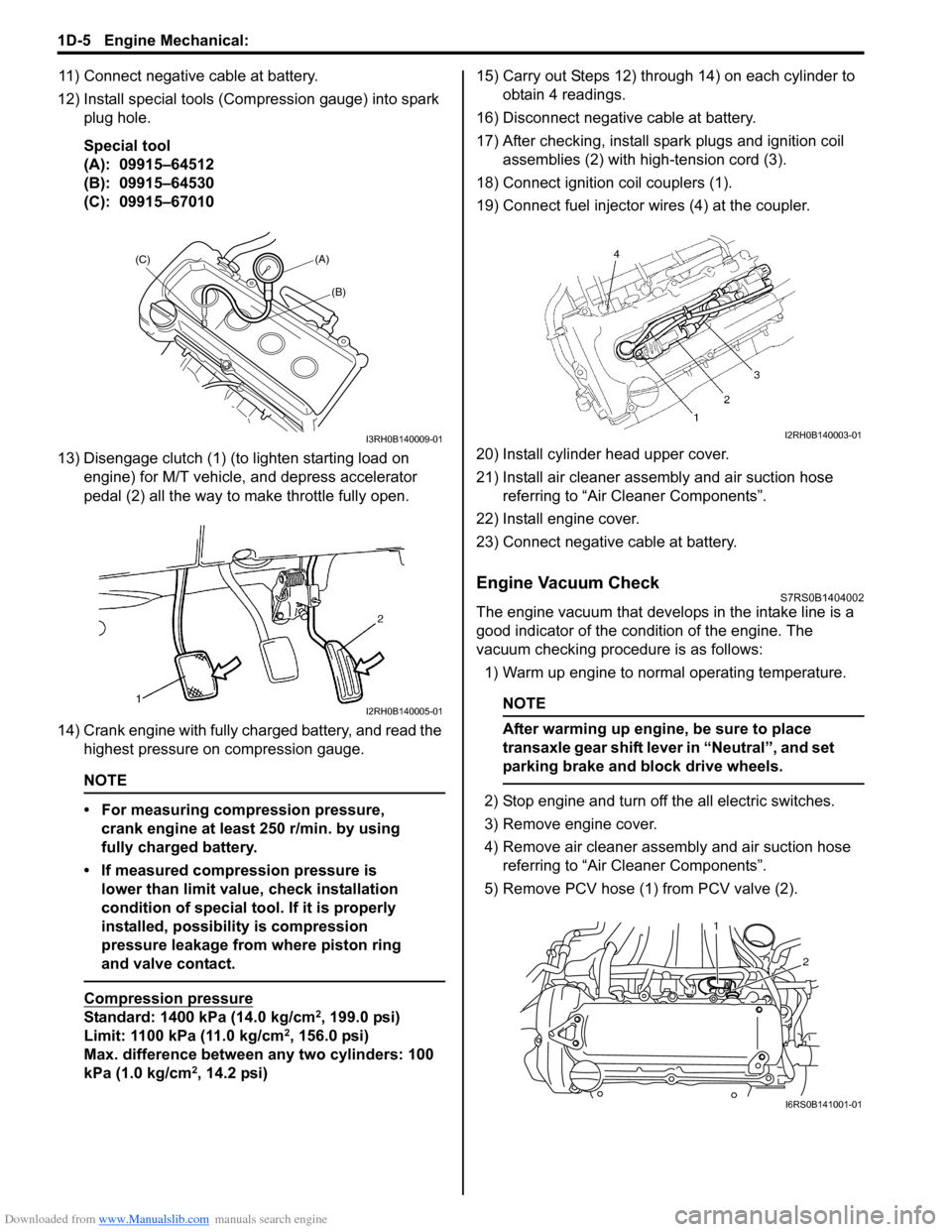
12) Install special tools (Compression gauge) into spark plug hole.
Special tool
(A): 09915–64512
(B): 09915–64530
(C): 09915–67010
13) Disengage clutch (1) (to lighten starting load on engine) for M/T vehicle, and depress accelerator
pedal (2) all the way to make throttle fully open.
14) Crank engine with fully charged battery, and read the highest pressure on compression gauge.
NOTE
• For measuring compression pressure, crank engine at least 250 r/min. by using
fully charged battery.
• If measured compression pressure is lower than limit value, check installation
condition of special tool. If it is properly
installed, possibility is compression
pressure leakage from where piston ring
and valve contact.
Compression pressure
Standard: 1400 kPa (14.0 kg/cm2, 199.0 psi)
Limit: 1100 kPa (11.0 kg/cm2, 156.0 psi)
Max. difference between any two cylinders: 100
kPa (1.0 kg/cm
2, 14.2 psi) 15) Carry out Steps 12) through 14) on each cylinder to
obtain 4 readings.
16) Disconnect negative cable at battery.
17) After checking, install spark plugs and ignition coil assemblies (2) with high-tension cord (3).
18) Connect ignition coil couplers (1).
19) Connect fuel injector wires (4) at the coupler.
20) Install cylinder head upper cover.
21) Install air cleaner assembly and air suction hose referring to “Air Cleaner Components”.
22) Install engine cover.
23) Connect negative cable at battery.
Engine Vacuum CheckS7RS0B1404002
The engine vacuum that develops in the intake line is a
good indicator of the condition of the engine. The
vacuum checking procedure is as follows:
1) Warm up engine to normal operating temperature.
NOTE
After warming up engine, be sure to place
transaxle gear shift lever in “Neutral”, and set
parking brake and block drive wheels.
2) Stop engine and turn off the all electric switches.
3) Remove engine cover.
4) Remove air cleaner assembly and air suction hose referring to “Air Cleaner Components”.
5) Remove PCV hose (1) from PCV valve (2).
(A)
(C)
(B)
I3RH0B140009-01
I2RH0B140005-01
I2RH0B140003-01
2
1
I6RS0B141001-01
Page 382 of 1496
Downloaded from www.Manualslib.com manuals search engine 1G-7 Fuel System:
Fuel Pressure Relief ProcedureS7RS0B1706003
CAUTION!
This work must not be done when engine is
hot. If done so, it may cause adverse effect to
catalyst.
NOTE
If ECM detects DTC(s) after servicing, clear
DTC(s) referring to “DTC Clearance in
Section 1A”.
1) Make sure that engine is cold.
2) Shift transaxle gear shift lever in “Neutral” (shift select lever in “P” range for A/T model), set parking
brake and block drive wheels.
3) Remove relay / fuse box cover.
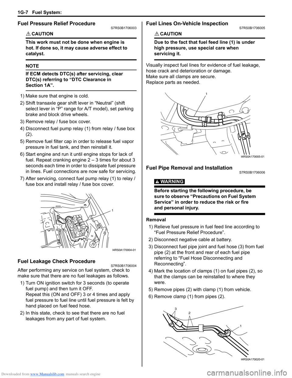
4) Disconnect fuel pump relay (1) from relay / fuse box (2).
5) Remove fuel filter cap in order to release fuel vapor pressure in fuel tank, and then reinstall it.
6) Start engine and run it until engine stops for lack of fuel. Repeat cranking engine 2 – 3 times for about 3
seconds each time in order to dissipate fuel pressure
in lines. Fuel connections are now safe for servicing.
7) After servicing, connect fuel pump relay (1) to relay / fuse box and install re lay / fuse box cover.
Fuel Leakage Check ProcedureS7RS0B1706004
After performing any service on fuel system, check to
make sure that there are no fuel leakages as follows.
1) Turn ON ignition switch for 3 seconds (to operate fuel pump) and then turn it OFF.
Repeat this (ON and OFF) 3 or 4 times and apply
fuel pressure to fuel line until fuel pressure is felt by
hand placed on fuel feed hose.
2) In this state, check to see that there are no fuel leakages from any part of fuel system.
Fuel Lines On-Vehicle InspectionS7RS0B1706005
CAUTION!
Due to the fact that fuel feed line (1) is under
high pressure, use special care when
servicing it.
Visually inspect fuel lines for evidence of fuel leakage,
hose crack and deterioration or damage.
Make sure all cl amps are secure.
Replace parts as needed.
Fuel Pipe Removal and InstallationS7RS0B1706006
WARNING!
Before starting the following procedure, be
sure to observe “Precautions on Fuel System
Service” in order to reduce the risk or fire
and personal injury.
Removal
1) Relieve fuel pressure in fuel feed line according to “Fuel Pressure Relief Procedure”.
2) Disconnect negative cable at battery.
3) Disconnect fuel pipe joint and fuel hose (3) from fuel pipe (2) at the front and rear of each fuel pipe
referring to “Fuel Hose Disconnecting and
Reconnecting”.
4) Mark the location of clamps (1) on fuel pipes (2), so that the clamps can be reinstalled to where they
were.
5) Remove pipes (2) with clamp (1) from vehicle.
6) Remove clamp (1) from pipes (2).
1
I4RS0A170004-01
1
I4RS0A170005-01
2
13
I4RS0A170020-01
Page 385 of 1496
Downloaded from www.Manualslib.com manuals search engine Fuel System: 1G-10
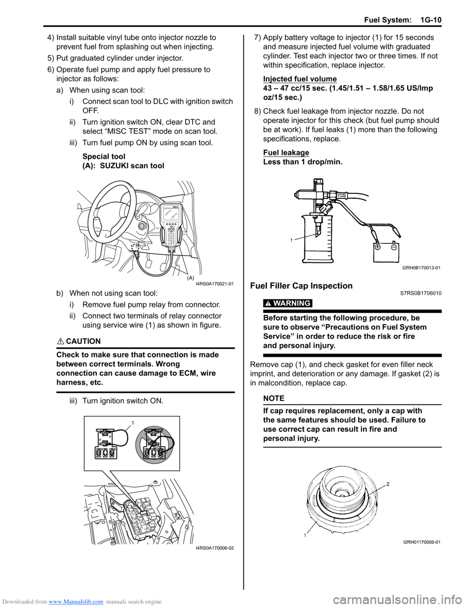
4) Install suitable vinyl tube onto injector nozzle to
prevent fuel from splashing out when injecting.
5) Put graduated cylinder under injector.
6) Operate fuel pump and apply fuel pressure to
injector as follows:
a) When using scan tool:
i) Connect scan tool to DLC with ignition switch OFF.
ii) Turn ignition switch ON, clear DTC and select “MISC TEST” mode on scan tool.
iii) Turn fuel pump ON by using scan tool.
Special tool
(A): SUZUKI scan tool
b) When not using scan tool: i) Remove fuel pump relay from connector.
ii) Connect two terminals of relay connector using service wire (1) as shown in figure.
CAUTION!
Check to make sure that connection is made
between correct terminals. Wrong
connection can cause damage to ECM, wire
harness, etc.
iii) Turn ignition switch ON. 7) Apply battery voltage to in
jector (1) for 15 seconds
and measure injected fuel volume with graduated
cylinder. Test each injector two or three times. If not
within specification, replace injector.
Injected fuel volume
43 – 47 cc/15 sec. (1.45/1.51 – 1.58/1.65 US/lmp
oz/15 sec.)
8) Check fuel leakage from injector nozzle. Do not operate injector for this check (but fuel pump should
be at work). If fuel leaks (1) more than the following
specifications, replace.
Fuel leakage
Less than 1 drop/min.
Fuel Filler Cap InspectionS7RS0B1706010
WARNING!
Before starting the following procedure, be
sure to observe “Precautions on Fuel System
Service” in order to reduce the risk or fire
and personal injury.
Remove cap (1), and che ck gasket for even filler neck
imprint, and deterioration or any damage. If gasket (2) is
in malcondition, replace cap.
NOTE
If cap requires replacement, only a cap with
the same features should be used. Failure to
use correct cap can result in fire and
personal injury.
(A)I4RS0A170021-01
1
I4RS0A170006-02
I2RH0B170013-01
I2RH01170008-01