lug bolts SUZUKI SWIFT 2007 2.G Service User Guide
[x] Cancel search | Manufacturer: SUZUKI, Model Year: 2007, Model line: SWIFT, Model: SUZUKI SWIFT 2007 2.GPages: 1496, PDF Size: 34.44 MB
Page 508 of 1496
Downloaded from www.Manualslib.com manuals search engine 4A-10 Brake Control System and Diagnosis:
7) Then attach bleeder plug cap.
8) After completing bleeding operation, apply fluid pressure to pipe line and check for leakage.
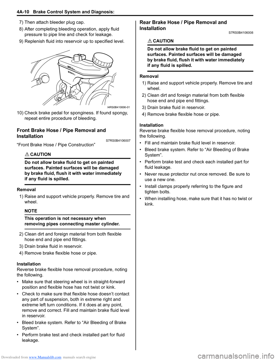
9) Replenish fluid into reserv oir up to specified level.
10) Check brake pedal for sponginess. If found spongy, repeat entire procedure of bleeding.
Front Brake Hose / Pipe Removal and
Installation
S7RS0B4106007
“Front Brake Hose / Pipe Construction”
CAUTION!
Do not allow brake fluid to get on painted
surfaces. Painted surfaces will be damaged
by brake fluid, flush it with water immediately
if any fluid is spilled.
Removal
1) Raise and support vehicle properly. Remove tire and wheel.
NOTE
This operation is not necessary when
removing pipes connecting master cylinder.
2) Clean dirt and foreign mate rial from both flexible
hose end and pipe end fittings.
3) Drain brake fluid in reservoir.
4) Remove brake flexible hose or pipe.
Installation
Reverse brake flexible hose removal procedure, noting
the following.
• Make sure that steering wh eel is in straight-forward
position and flexible hose has not twist or kink.
• Check to make sure that flexible hose doesn’t contact any part of suspension, both in extreme right and
extreme left turn conditions. If it does at any point,
remove and correct. Fill and maintain brake fluid level
in reservoir.
• Bleed brake system. Refer to “Air Bleeding of Brake System”.
• Perform brake test and check installed part for fluid leakage.
Rear Brake Hose / Pipe Removal and
Installation
S7RS0B4106008
CAUTION!
Do not allow brake fluid to get on painted
surfaces. Painted surfaces will be damaged
by brake fluid, flush it with water immediately
if any fluid is spilled.
Removal
1) Raise and support vehicle properly. Remove tire and wheel.
2) Clean dirt and foreign material from both flexible hose end and pipe end fittings.
3) Drain brake fluid in reservoir.
4) Remove brake flexible hose or pipe.
Installation
Reverse brake flexible hose removal procedure, noting
the following.
• Fill and maintain brake fluid level in reservoir.
• Bleed brake system. Refer to “Air Bleeding of Brake System”.
• Perform brake test and check each installed part for fluid leakage.
• Never reuse protector nut once removed. Be sure to use a new one.
• Install clamps properly referring to the figure and tighten bolts.
• When installing hose, make sure that it has no twist or
kink.
I4RS0B410006-01
Page 520 of 1496
Downloaded from www.Manualslib.com manuals search engine 4B-4 Front Brakes:
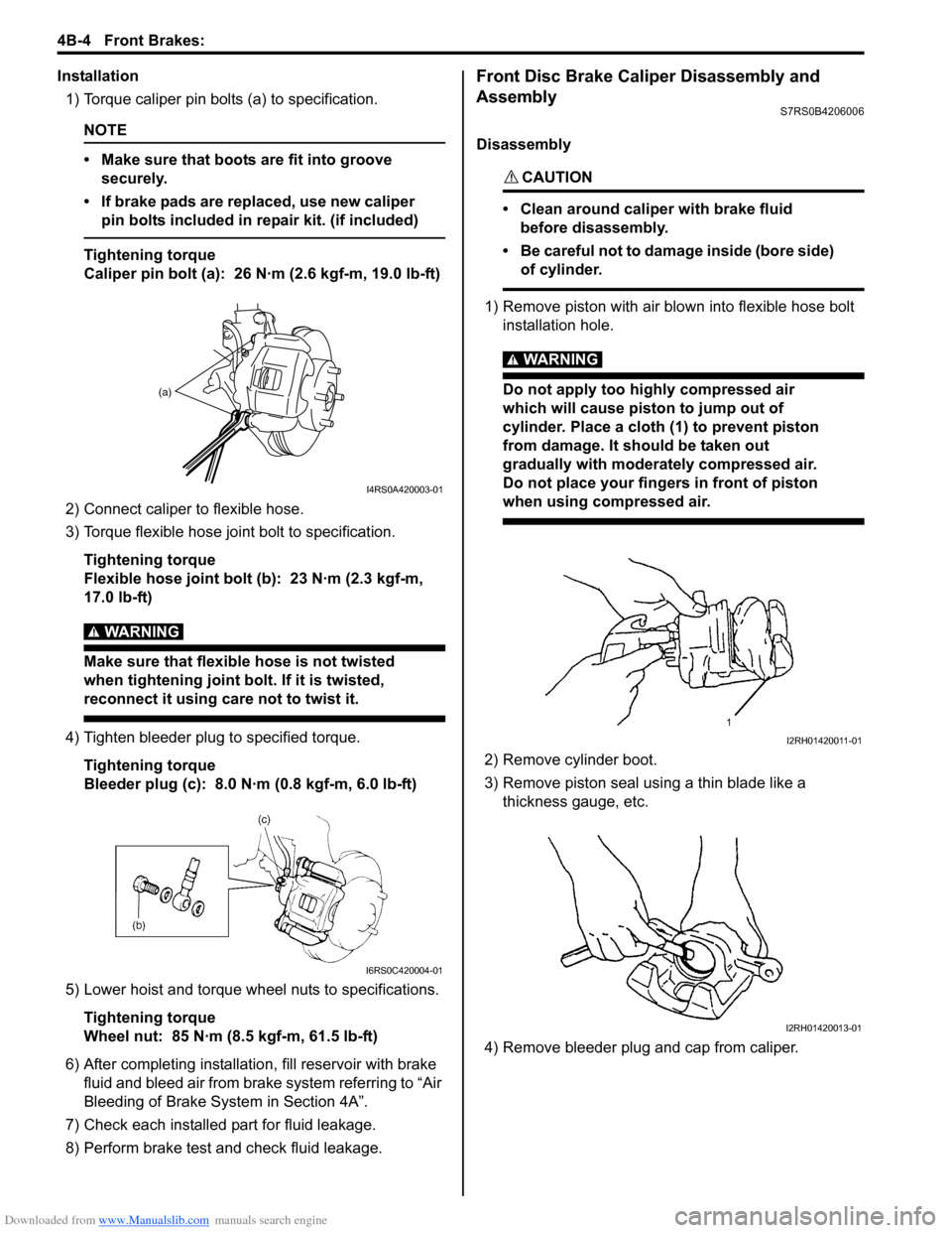
Installation1) Torque caliper pin bolts (a) to specification.
NOTE
• Make sure that boots are fit into groove securely.
• If brake pads are replaced, use new caliper pin bolts included in repair kit. (if included)
Tightening torque
Caliper pin bolt (a): 26 N·m (2.6 kgf-m, 19.0 lb-ft)
2) Connect caliper to flexible hose.
3) Torque flexible hose jo int bolt to specification.
Tightening torque
Flexible hose joint bolt (b): 23 N·m (2.3 kgf-m,
17.0 lb-ft)
WARNING!
Make sure that flexible hose is not twisted
when tightening joint bolt. If it is twisted,
reconnect it using care not to twist it.
4) Tighten bleeder plug to specified torque. Tightening torque
Bleeder plug (c): 8.0 N·m (0.8 kgf-m, 6.0 lb-ft)
5) Lower hoist and torque wheel nuts to specifications. Tightening torque
Wheel nut: 85 N·m (8.5 kgf-m, 61.5 lb-ft)
6) After completing installation, fill reservoir with brake
fluid and bleed air from brake system referring to “Air
Bleeding of Brake System in Section 4A”.
7) Check each installed part for fluid leakage.
8) Perform brake test and check fluid leakage.
Front Disc Brake Caliper Disassembly and
Assembly
S7RS0B4206006
Disassembly
CAUTION!
• Clean around caliper with brake fluid before disassembly.
• Be careful not to damage inside (bore side) of cylinder.
1) Remove piston with air blown into flexible hose bolt installation hole.
WARNING!
Do not apply too highly compressed air
which will cause piston to jump out of
cylinder. Place a cloth (1) to prevent piston
from damage. It should be taken out
gradually with moderately compressed air.
Do not place your fingers in front of piston
when using compressed air.
2) Remove cylinder boot.
3) Remove piston seal using a thin blade like a thickness gauge, etc.
4) Remove bleeder plug and cap from caliper.
(a)
I4RS0A420003-01
I6RS0C420004-01
I2RH01420011-01
I2RH01420013-01
Page 527 of 1496
Downloaded from www.Manualslib.com manuals search engine Rear Brakes: 4C-3
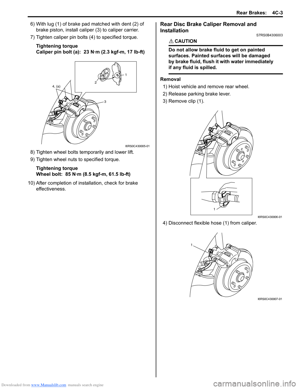
6) With lug (1) of brake pad matched with dent (2) of brake piston, install caliper (3) to caliper carrier.
7) Tighten caliper pin bolts (4) to specified torque.
Tightening torque
Caliper pin bolt (a): 23 N·m (2.3 kgf-m, 17 lb-ft)
8) Tighten wheel bolts temporarily and lower lift.
9) Tighten wheel nuts to specified torque. Tightening torque
Wheel bolt: 85 N·m (8.5 kgf-m, 61.5 lb-ft)
10) After completion of installation, check for brake effectiveness.Rear Disc Brake Caliper Removal and
Installation
S7RS0B4306003
CAUTION!
Do not allow brake fluid to get on painted
surfaces. Painted surfaces will be damaged
by brake fluid, flush it with water immediately
if any fluid is spilled.
Removal
1) Hoist vehicle and remove rear wheel.
2) Release parking brake lever.
3) Remove clip (1).
4) Disconnect flexible hose (1) from caliper.
4, (a) 21
3
I6RS0C430005-01
1
I6RS0C430006-01
1
I6RS0C430007-01
Page 569 of 1496
Downloaded from www.Manualslib.com manuals search engine ABS: 4E-30
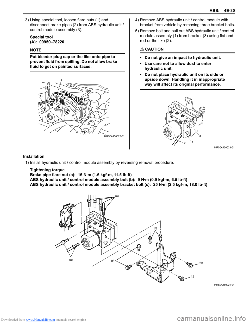
3) Using special tool, loosen flare nuts (1) and disconnect brake pipes (2) from ABS hydraulic unit /
control module assembly (3).
Special tool
(A): 09950–78220
NOTE
Put bleeder plug cap or the like onto pipe to
prevent fluid from spilli ng. Do not allow brake
fluid to get on painted surfaces.
4) Remove ABS hydraulic unit / control module with
bracket from vehicle by removing three bracket bolts.
5) Remove bolt and pull out ABS hydraulic unit / control module assembly (1) from bracket (3) using flat end
rod or the like (2).
CAUTION!
• Do not give an impact to hydraulic unit.
• Use care not to allow dust to enter hydraulic unit.
• Do not place hydraulic unit on its side or upside down. Handling it in inappropriate
way will affect its original performance.
Installation
1) Install hydraulic unit / control module assembly by reversing removal procedure.
Tightening torque
Brake pipe flare nut (a): 16 N·m (1.6 kgf-m, 11.5 lb-ft)
ABS hydraulic unit / control module assembly bolt (b): 9 N·m (0.9 kgf-m, 6.5 lb-ft)
ABS hydraulic unit / control module assembly bracket bolt (c): 25 N·m (2.5 kgf-m, 18.0 lb-ft)
3
2
1
(A)
I4RS0A450022-01
1
3
2
I4RS0A450023-01
(a) (a)(c)
(c)
(b)
(b)
I4RS0A450024-01
Page 742 of 1496
Downloaded from www.Manualslib.com manuals search engine 5A-98 Automatic Transmission/Transaxle:
Transmission Fluid Temperature Sensor
Inspection
S7RS0B5106021
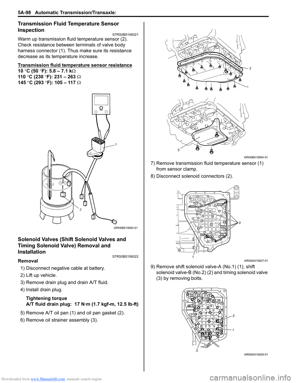
Warm up transmission fluid temperature sensor (2).
Check resistance between terminals of valve body
harness connector (1). Thus make sure its resistance
decrease as its temperature increase.
Transmission fluid temperature sensor resistance
10 °C (50 °F): 5.8 – 7.1 k Ω
110 °C (230 °F): 231 – 263 Ω
145 °C (293 °F): 105 – 117 Ω
Solenoid Valves (Shift Solenoid Valves and
Timing Solenoid Valve) Removal and
Installation
S7RS0B5106022
Removal
1) Disconnect negative cable at battery.
2) Lift up vehicle.
3) Remove drain plug and drain A/T fluid.
4) Install drain plug.
Tightening torque
A/T fluid drain plug: 17 N· m (1.7 kgf-m, 12.5 lb-ft)
5) Remove A/T oil pan (1) and oil pan gasket (2).
6) Remove oil strain er assembly (3). 7) Remove transmission fluid temperature sensor (1)
from sensor clamp.
8) Disconnect solenoid connectors (2).
9) Remove shift solenoid va lve-A (No.1) (1), shift
solenoid valve-B (No.2) (2) and timing solenoid valve
(3) by removing bolts.
I2RH0B510052-01
I2RH0B510054-01
1 2I4RS0A510027-01
1
2
3
I4RS0A510028-01
Page 757 of 1496

Downloaded from www.Manualslib.com manuals search engine Automatic Transmission/Transaxle: 5A-113
19) Remove transaxle case plug (1).
20) Remove torque converter housing bolts.
21) Remove torque converter housing (1) while tapping
around it lightly with plastic hammer.
22) Remove breather hose (1).
23) Remove breather union (2).
24) Measure input shaft thrust play. Apply dial gauge onto input shaft end (1) and
measure thrust play of input shaft.
When input shaft thrust play is out of specification,
select input shaft front th rust bearing with proper
thickness from among the list below and replace it.
Special tool
(A): 09900–20607
(B): 09900-20701
Input shaft thrust play
0.3 – 0.9 mm (0.012 – 0.035 in.)
Available input shaft front thrust bearing
thickness
: 3.45, 4.05 mm (0.136, 0.159 in.) 25) Remove oil pump assembly (1).
26) Remove direct clutch assembly (1).
27) Remove input shaft front thrust bearing (1).
NOTE
If input shaft front thrust bearing is not
found, it may have been taken out with oil
pump assembly.
I2RH0B510095-01
I3RM0B510060-01
1
2
I2RH0B510097-01
I2RH0B510098-01
I2RH0B510099-01
I2RH0B510100-01
I2RH0B510101-01
Page 849 of 1496
Downloaded from www.Manualslib.com manuals search engine Manual Transmission/Transaxle: 5B-35
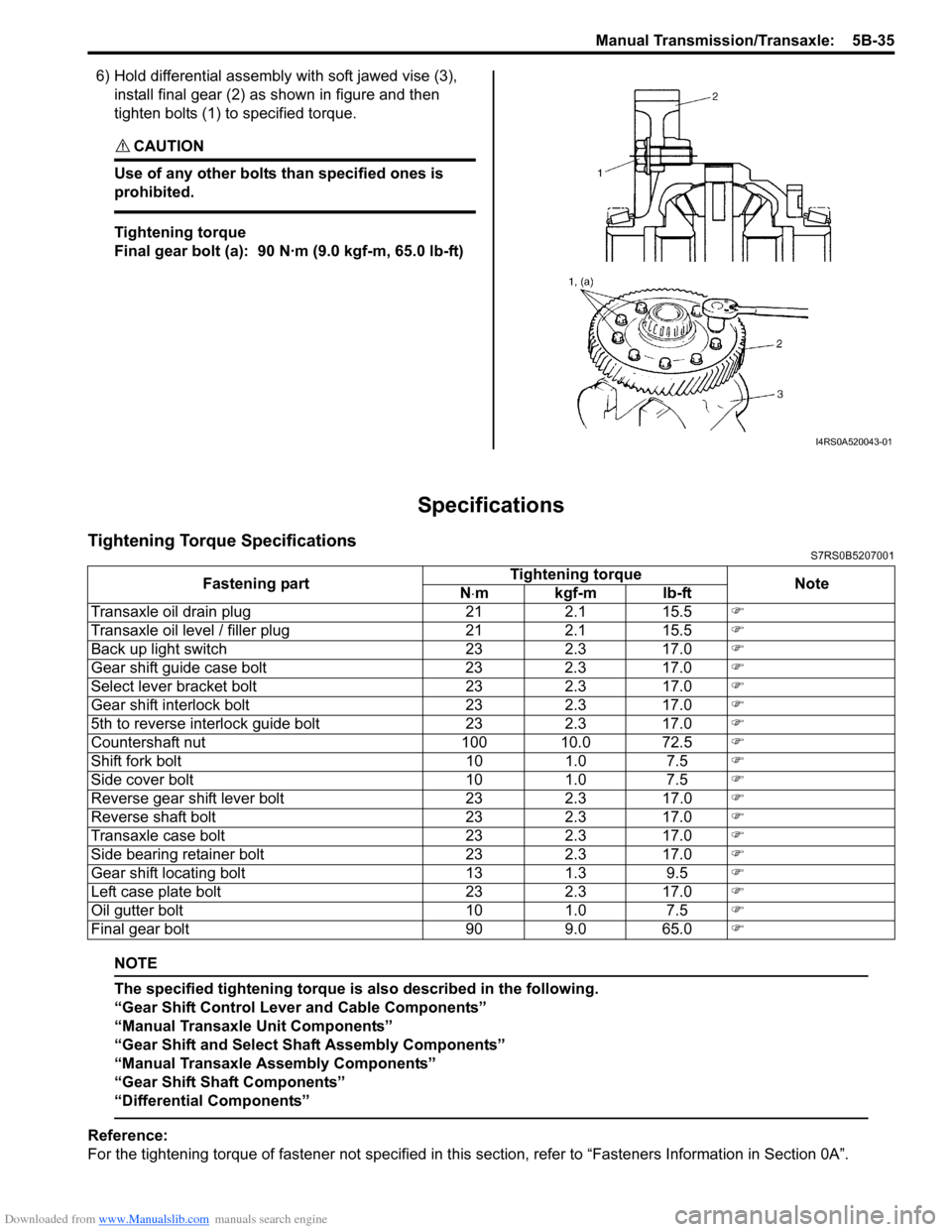
6) Hold differential assembly with soft jawed vise (3),
install final gear (2) as shown in figure and then
tighten bolts (1) to specified torque.
CAUTION!
Use of any other bolts than specified ones is
prohibited.
Tightening torque
Final gear bolt (a): 90 N·m (9.0 kgf-m, 65.0 lb-ft)
Specifications
Tightening Torque SpecificationsS7RS0B5207001
NOTE
The specified tightening torque is also described in the following.
“Gear Shift Control Leve r and Cable Components”
“Manual Transaxle Unit Components”
“Gear Shift and Select Shaft Assembly Components”
“Manual Transaxle Assembly Components”
“Gear Shift Shaft Components”
“Differential Components”
Reference:
For the tightening torque of fastener not specified in this section, refer to “Fasteners Information in Section 0A”.
I4RS0A520043-01
Fastening part Tightening torque
Note
N ⋅mkgf-mlb-ft
Transaxle oil drain plug 21 2.1 15.5 �)
Transaxle oil level / filler plug 21 2.1 15.5 �)
Back up light switch 23 2.3 17.0 �)
Gear shift guide case bolt 23 2.3 17.0 �)
Select lever bracket bolt 23 2.3 17.0 �)
Gear shift interlock bolt 23 2.3 17.0 �)
5th to reverse interlock guide bolt 23 2.3 17.0 �)
Countershaft nut 100 10.0 72.5 �)
Shift fork bolt 10 1.0 7.5 �)
Side cover bolt 10 1.0 7.5 �)
Reverse gear shift lever bolt 23 2.3 17.0 �)
Reverse shaft bolt 23 2.3 17.0 �)
Transaxle case bolt 23 2.3 17.0 �)
Side bearing retainer bolt 23 2.3 17.0 �)
Gear shift locating bolt 13 1.3 9.5 �)
Left case plate bolt 23 2.3 17.0 �)
Oil gutter bolt 10 1.0 7.5 �)
Final gear bolt 90 9.0 65.0 �)
Page 970 of 1496
Downloaded from www.Manualslib.com manuals search engine 7B-22 Air Conditioning System: Manual Type
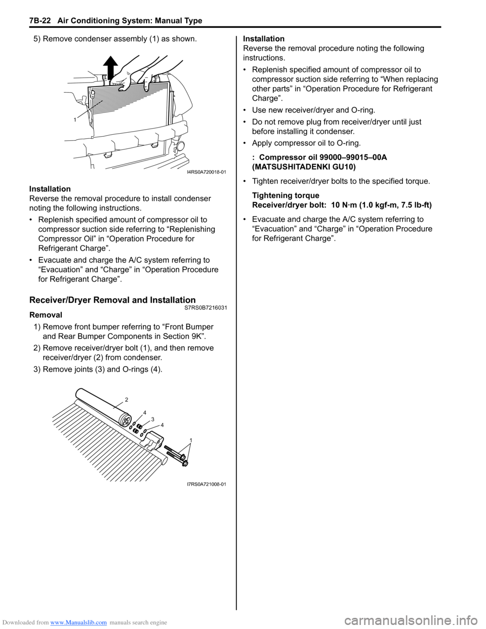
5) Remove condenser assembly (1) as shown.
Installation
Reverse the removal procedure to install condenser
noting the following instructions.
• Replenish specified amount of compressor oil to compressor suction side referring to “Replenishing
Compressor Oil” in “Operation Procedure for
Refrigerant Charge”.
• Evacuate and charge the A/C system referring to “Evacuation” and “Charge” in “Operation Procedure
for Refrigerant Charge”.
Receiver/Dryer Removal and InstallationS7RS0B7216031
Removal
1) Remove front bumper referring to “Front Bumper and Rear Bumper Components in Section 9K”.
2) Remove receiver/dryer bolt (1), and then remove receiver/dryer (2) from condenser.
3) Remove joints (3) and O-rings (4). Installation
Reverse the removal procedure noting the following
instructions.
• Replenish specified amount of compressor oil to
compressor suction side referring to “When replacing
other parts” in “Operation Procedure for Refrigerant
Charge”.
• Use new receiver/dryer and O-ring.
• Do not remove plug from receiver/dryer until just before installin g it condenser.
• Apply compressor oil to O-ring.
: Compressor oil 99000–99015–00A
(MATSUSHITADENKI GU10)
• Tighten receiver/dryer bolts to the specified torque. Tightening torque
Receiver/dryer bolt: 10 N· m (1.0 kgf-m, 7.5 lb-ft)
• Evacuate and charge the A/C system referring to “Evacuation” and “Charge” in “Operation Procedure
for Refrigerant Charge”.
1
I4RS0A720018-01
1
4
4
3
2
I7RS0A721008-01
Page 1287 of 1496
Downloaded from www.Manualslib.com manuals search engine Lighting Systems: 9B-5
Interior Light Symptom DiagnosisS7RS0B9204008
NOTE
• Use of SUZUKI scan tool makes it easy to check whether a faulty condition is on the input side or
output side of BCM. For checking procedure, re fer to “Diagnosis Using Output Test Function of
SUZUKI Scan Tool” under “Scan Tool Data in Section 10B”.
• Check each part in the order from the top of the following list.
Repair Instructions
Headlight Housing Removal and InstallationS7RS0B9206001
Removal 1) Disconnect negative (–) cable at battery.
2) Remove front bumper. Refer to “Front Bumper and Rear Bumper Componen ts in Section 9K”.
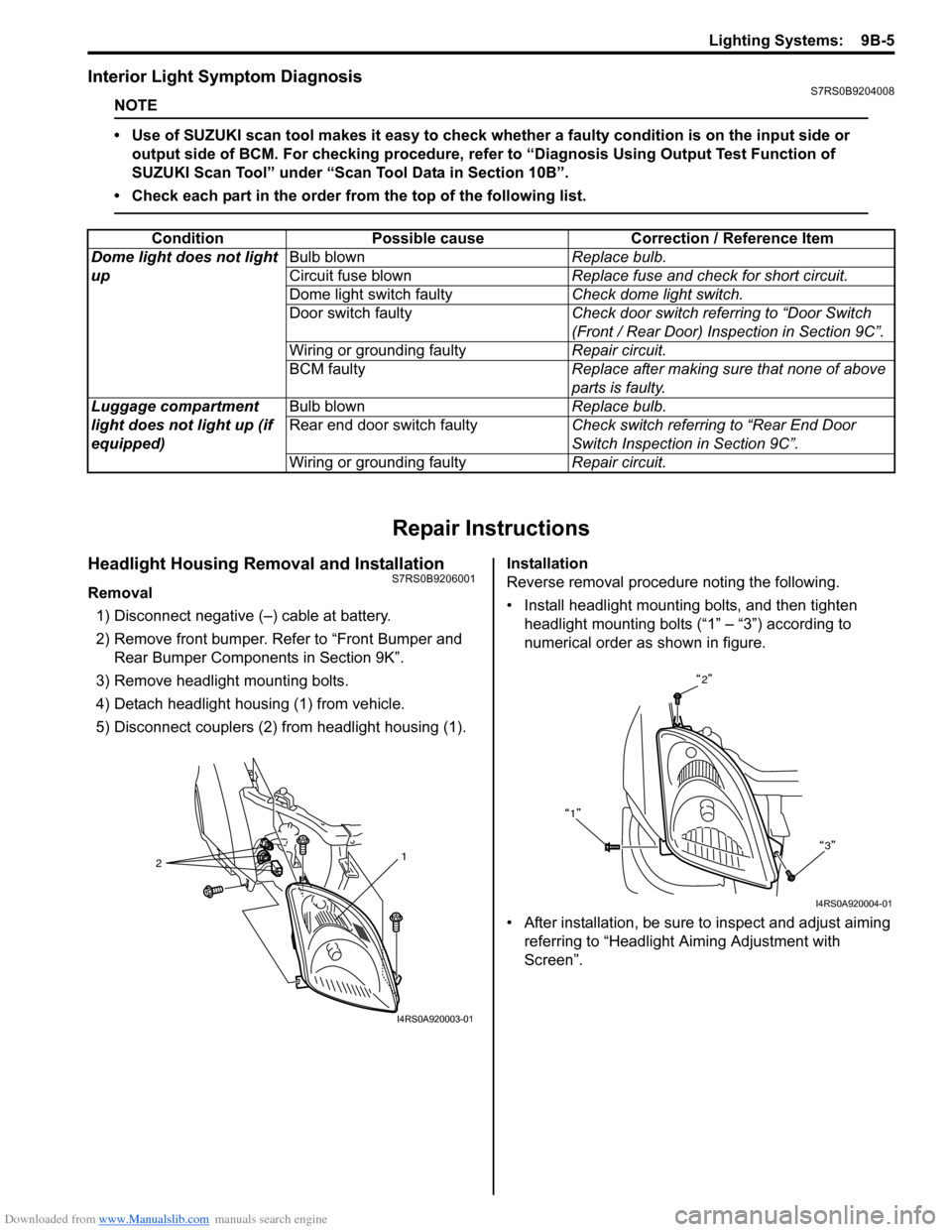
3) Remove headlight mounting bolts.
4) Detach headlight housing (1) from vehicle.
5) Disconnect couplers (2) from headlight housing (1). Installation
Reverse removal procedure noting the following.
• Install headlight mounting bolts, and then tighten
headlight mounting bolts (“1” – “3”) according to
numerical order as shown in figure.
• After installation, be sure to inspect and adjust aiming referring to “Headlight Aiming Adjustment with
Screen”.
Condition Possible cause Correction / Reference Item
Dome light does not light
up Bulb blown
Replace bulb.
Circuit fuse blown Replace fuse and check for short circuit.
Dome light switch faulty Check dome light switch.
Door switch faulty Check door switch referring to “Door Switch
(Front / Rear Door) Inspection in Section 9C”.
Wiring or grounding faulty Repair circuit.
BCM faulty Replace after making sure that none of above
parts is faulty.
Luggage compartment
light does not light up (if
equipped) Bulb blown
Replace bulb.
Rear end door switch faulty Check switch referring to “Rear End Door
Switch Inspection in Section 9C”.
Wiring or grounding faulty Repair circuit.
2 1
I4RS0A920003-01
2
1 3
I4RS0A920004-01