rear pin SUZUKI SWIFT 2007 2.G Service User Guide
[x] Cancel search | Manufacturer: SUZUKI, Model Year: 2007, Model line: SWIFT, Model: SUZUKI SWIFT 2007 2.GPages: 1496, PDF Size: 34.44 MB
Page 462 of 1496
Downloaded from www.Manualslib.com manuals search engine 2C-8 Rear Suspension:
3) Install coil springs (right & left) on spring seats of rear
axle referring to “Spring Upper Seat and Lower Seat
Removal and Installation” and “Rear Coil Spring
Removal and Installation”.
4) Install shock absorbers lower side (right & left) and washers referring to “Rear Shock Absorber Removal
and Installation”.
5) Install brake dust covers, spindles and wheel speed sensors (right and left) referring to “Spindle Removal
and Installation”.
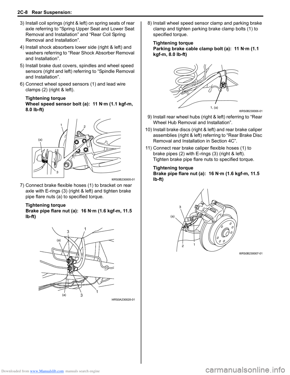
6) Connect wheel speed sensors (1) and lead wire clamps (2) (right & left).
Tightening torque
Wheel speed sensor bolt (a): 11 N·m (1.1 kgf-m,
8.0 lb-ft)
7) Connect brake flexible hoses (1) to bracket on rear axle with E-rings (3) (right & left) and tighten brake
pipe flare nuts (a) to specified torque.
Tightening torque
Brake pipe flare nut (a): 16 N·m (1.6 kgf-m, 11.5
lb-ft) 8) Install wheel speed sensor clamp and parking brake
clamp and tighten parking brake clamp bolts (1) to
specified torque.
Tightening torque
Parking brake cable clamp bolt (a): 11 N·m (1.1
kgf-m, 8.0 lb-ft)
9) Install rear wheel hubs (right & left) referring to “Rear Wheel Hub Removal and Installation”.
10) Install brake discs (right & left) and rear brake caliper assemblies (right & left) referring to “Rear Brake Disc
Removal and Installati on in Section 4C”.
11) Connect rear brake caliper flexible hoses (1) to brake pipes (2) with E-rings (3) (right & left).
Tighten brake pipe flare nuts to specified torque.
Tightening torque
Brake pipe flare nut (a): 16 N·m (1.6 kgf-m, 11.5
lb-ft)
1 2
(a)
3
I6RS0B230005-01
I4RS0A230028-01
1, (a)I6RS0B230006-01
3
2 1
(a)
I6RS0B230007-01
Page 464 of 1496
Downloaded from www.Manualslib.com manuals search engine 2C-10 Rear Suspension:
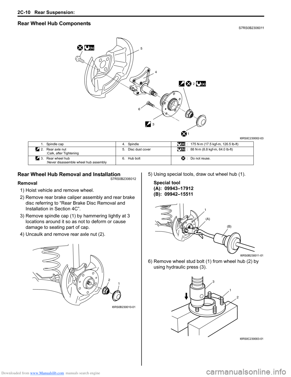
Rear Wheel Hub ComponentsS7RS0B2306011
Rear Wheel Hub Removal and InstallationS7RS0B2306012
Removal1) Hoist vehicle and remove wheel.
2) Remove rear brake caliper assembly and rear brake disc referring to “Rear Brake Disc Removal and
Installation in Section 4C”.
3) Remove spindle cap (1) by hammering lightly at 3 locations around it so as not to deform or cause
damage to seating part of cap.
4) Uncaulk and remove rear axle nut (2). 5) Using special tools, draw out wheel hub (1).
Special tool
(A): 09943–17912
(B): 09942–15511
6) Remove wheel stud bolt (1) from wheel hub (2) by using hydraulic press (3).
(b)5
4
3
(a)2
1
6
I6RS0C230002-03
1. Spindle cap 4. Spindle: 175 N⋅m (17.5 kgf-m, 126.5 lb-ft)
2. Rear axle nut :Calk, after Tightening 5. Disc dust cover
: 88 N⋅m (8.8 kgf-m, 64.0 lb-ft)
3. Rear wheel hub :Never disassemble wheel hub assembly 6. Hub bolt
: Do not reuse.
2
1
I6RS0B230010-01
1
(A) (B)
I6RS0B230011-01
1
3
2
I6RS0C230003-01
Page 465 of 1496
Downloaded from www.Manualslib.com manuals search engine Rear Suspension: 2C-11
Installation
Install wheel hub by reversing removal procedure noting
the following instructions.
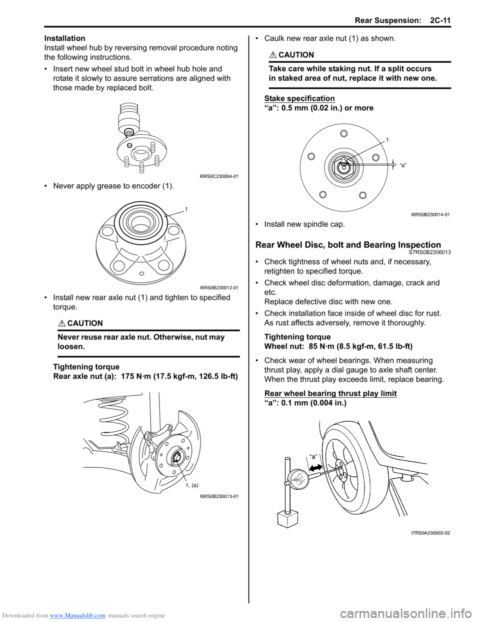
• Insert new wheel stud bolt in wheel hub hole and rotate it slowly to assure serrations are aligned with
those made by replaced bolt.
• Never apply grease to encoder (1).
• Install new rear axle nut (1) and tighten to specified torque.
CAUTION!
Never reuse rear axle nut. Otherwise, nut may
loosen.
Tightening torque
Rear axle nut (a): 175 N·m (17.5 kgf-m, 126.5 lb-ft) • Caulk new rear axle nut (1) as shown.
CAUTION!
Take care while staking nut. If a split occurs
in staked area of nut,
replace it with new one.
Stake specification
“a”: 0.5 mm (0.02 in.) or more
• Install new spindle cap.
Rear Wheel Disc, bolt and Bearing InspectionS7RS0B2306013
• Check tightness of wheel nuts and, if necessary, retighten to specified torque.
• Check wheel disc deformation, damage, crack and etc.
Replace defective disc with new one.
• Check installation face insi de of wheel disc for rust.
As rust affects adversely, remove it thoroughly.
Tightening torque
Wheel nut: 85 N·m (8.5 kgf-m, 61.5 lb-ft)
• Check wear of wheel bearings. When measuring thrust play, apply a dial gauge to axle shaft center.
When the thrust play exce eds limit, replace bearing.
Rear wheel bearing thrust play
limit
“a”: 0.1 mm (0.004 in.)
I6RS0C230004-01
1
I6RS0B230012-01
1, (a)
I6RS0B230013-01
1
“a”
I6RS0B230014-01
I7RS0A230002-02
Page 466 of 1496
Downloaded from www.Manualslib.com manuals search engine 2C-12 Rear Suspension:
• Check noise and smooth rotation of wheel by rotating wheel. If it is defect ive, replace bearing.
Spindle Removal and InstallationS7RS0B2306014
Removal
1) Remove rear brake caliper assembly and brake disc. For details, refer to Step 2) to 4) of “Removal” under
“Rear Brake Disc Removal and Installation in
Section 4C”.
2) Remove rear wheel hub. For details, refer to Step 3) to 5) of “Removal” under “Rear Wheel Hub Removal
and Installation”.
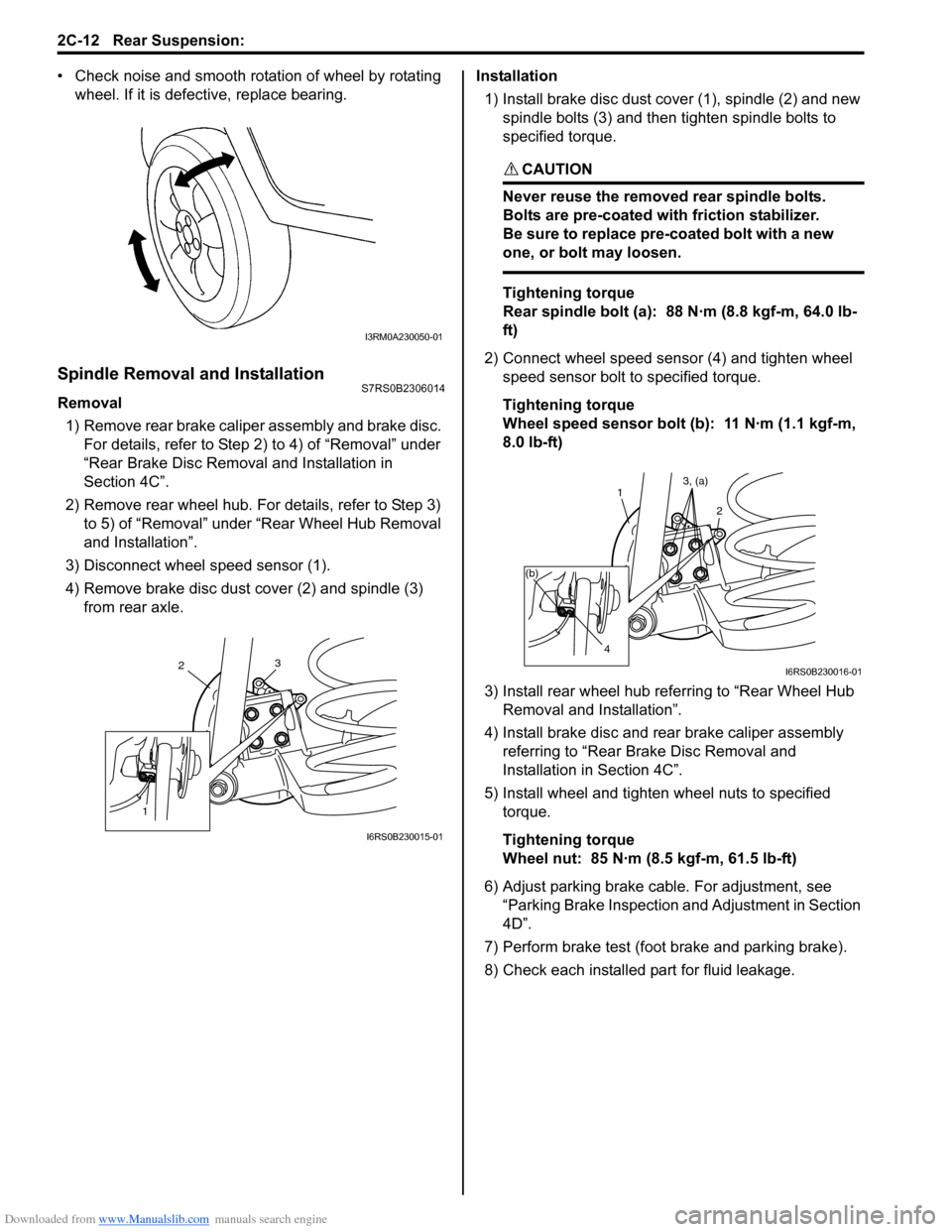
3) Disconnect wheel speed sensor (1).
4) Remove brake disc dust cover (2) and spindle (3) from rear axle. Installation
1) Install brake disc dust cover (1), spindle (2) and new spindle bolts (3) and then tighten spindle bolts to
specified torque.
CAUTION!
Never reuse the removed rear spindle bolts.
Bolts are pre-coated wi th friction stabilizer.
Be sure to replace pre-coated bolt with a new
one, or bolt may loosen.
Tightening torque
Rear spindle bolt (a): 88 N·m (8.8 kgf-m, 64.0 lb-
ft)
2) Connect wheel speed sensor (4) and tighten wheel speed sensor bolt to specified torque.
Tightening torque
Wheel speed sensor bolt (b): 11 N·m (1.1 kgf-m,
8.0 lb-ft)
3) Install rear wheel hub re ferring to “Rear Wheel Hub
Removal and Installation”.
4) Install brake disc and rear brake caliper assembly referring to “Rear Brake Disc Removal and
Installation in Section 4C”.
5) Install wheel and tighten wheel nuts to specified torque.
Tightening torque
Wheel nut: 85 N·m (8.5 kgf-m, 61.5 lb-ft)
6) Adjust parking brake cable. For adjustment, see “Parking Brake Inspection and Adjustment in Section
4D”.
7) Perform brake test (foot brake and parking brake).
8) Check each installed part for fluid leakage.
I3RM0A230050-01
2
1 3
I6RS0B230015-01
1
(b)
4
2
3, (a)
I6RS0B230016-01
Page 467 of 1496
Downloaded from www.Manualslib.com manuals search engine Rear Suspension: 2C-13
Spindle InspectionS7RS0B2306015
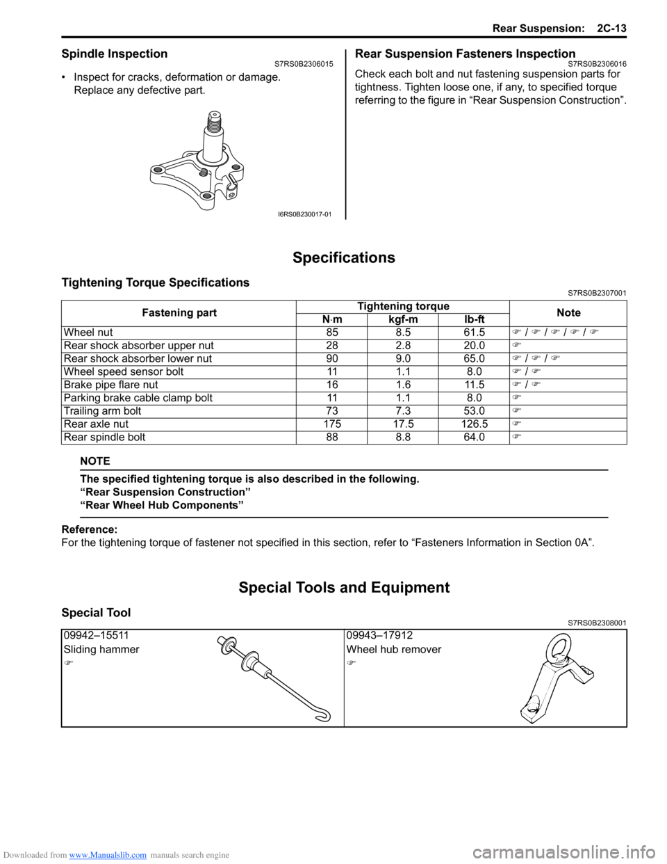
• Inspect for cracks, deformation or damage.Replace any defective part.
Rear Suspension Fasteners InspectionS7RS0B2306016
Check each bolt and nut fastening suspension parts for
tightness. Tighten loose one, if any, to specified torque
referring to the figure in “Rear Suspension Construction”.
Specifications
Tightening Torque SpecificationsS7RS0B2307001
NOTE
The specified tightening torque is also described in the following.
“Rear Suspension Construction”
“Rear Wheel Hub Components”
Reference:
For the tightening torque of fastener not specified in this section, refer to “Fasteners Information in Section 0A”.
Special Tools and Equipment
Special ToolS7RS0B2308001
I6RS0B230017-01
Fastening part Tightening torque
Note
N ⋅mkgf-mlb-ft
Wheel nut 85 8.5 61.5 �) / �) / �) / �) / �)
Rear shock absorber upper nut 28 2.8 20.0 �)
Rear shock absorber lower nut 90 9.0 65.0 �) / �) / �)
Wheel speed sensor bolt 11 1.1 8.0 �) / �)
Brake pipe flare nut 16 1.6 11.5 �) / �)
Parking brake cable clamp bolt 11 1.1 8.0 �)
Trailing arm bolt 73 7.3 53.0 �)
Rear axle nut 175 17.5 126.5 �)
Rear spindle bolt 88 8.8 64.0 �)
09942–1551109943–17912
Sliding hammer Wheel hub remover
�)�)
Page 470 of 1496
Downloaded from www.Manualslib.com manuals search engine 2D-3 Wheels and Tires:
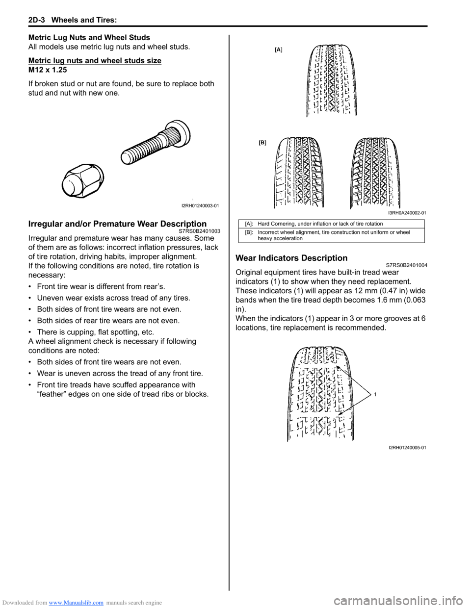
Metric Lug Nuts and Wheel Studs
All models use metric lug nuts and wheel studs.
Metric lug nuts and wheel studs size
M12 x 1.25
If broken stud or nut are found, be sure to replace both
stud and nut with new one.
Irregular and/or Premature Wear DescriptionS7RS0B2401003
Irregular and premature wear has many causes. Some
of them are as follows: incorrect inflation pressures, lack
of tire rotation, driving habits, improper alignment.
If the following conditions are noted, tire rotation is
necessary:
• Front tire wear is different from rear’s.
• Uneven wear exists across tread of any tires.
• Both sides of front tire wears are not even.
• Both sides of rear tire wears are not even.
• There is cupping, flat spotting, etc.
A wheel alignment check is necessary if following
conditions are noted:
• Both sides of front tire wears are not even.
• Wear is uneven across the tread of any front tire.
• Front tire treads have scuffed appearance with “feather” edges on one side of tread ribs or blocks.
Wear Indicators DescriptionS7RS0B2401004
Original equipment tires have built-in tread wear
indicators (1) to show when they need replacement.
These indicators (1) will app ear as 12 mm (0.47 in) wide
bands when the tire tread depth becomes 1.6 mm (0.063
in).
When the indicators (1) appear in 3 or more grooves at 6
locations, tire replacement is recommended.
I2RH01240003-01
[A]: Hard Cornering, under inflation or lack of tire rotation
[B]: Incorrect wheel alignment, tire construction not uniform or wheel heavy acceleration
I3RH0A240002-01
I2RH01240005-01
Page 472 of 1496
Downloaded from www.Manualslib.com manuals search engine 2D-5 Wheels and Tires:
Radial Tire Lead / Pull DescriptionS7RS0B2401006
“Lead / Pull” is the deviation of the vehicle from a straight
path on a level road even with no pressure on the
steering wheel.
Lead is usually caused by the following conditions.
• Improper tire and wheel alignment.
• Uneven brake assemblies.
• Tire construction.
The way in which a tire is built can produce lead in a
vehicle. An example of this is placement of the belt. Off
center belts on radial tires can cause the tire to develop
a side force while rolling straight down the road. If one
side of the tire has a little larger diameter than the other,
the tire will tend to roll to one side. This will develop a
side force which can produce vehicle lead.
The procedure in the figure (Lead Diagnosis) should be
used to make sure that wheel alignment is not mistaken
for tire lead.
• Part of the lead diagnosis procedure is different from the proper tire rotation pattern currently in the owner
and service manuals. If a medium to high mileage tire
is moved to the other side of the vehicle, be sure to
check that ride roughness has not developed.
• Rear tires will not cause lead.
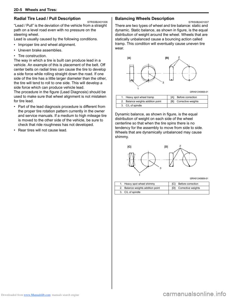
Balancing Wheels DescriptionS7RS0B2401007
There are two types of wheel an d tire balance: static and
dynamic. Static balance, as shown in figure, is the equal
distribution of weight around the wheel. Wheels that are
statically unbalanced cause a bouncing action called
tramp. This condition will eventually cause uneven tire
wear.
Dynamic balance, as shown in figure, is the equal
distribution of weight on each side of the wheel
centerline so that when the tire spins there is no
tendency for the assembly to move from side to side.
Wheels that are dynamically unbalanced may cause
shimmy.
1. Heavy spot wheel tramp [A]: Before correction
2. Balance weights addition point [B]: Corrective weights
3. C/L of spindle
1. Heavy spot wheel shimmy [C]: Before correction
2. Balance weights addition point [D]: Corrective weights
3. C/L of spindle
I2RH01240008-01
I2RH01240009-01
Page 503 of 1496
Downloaded from www.Manualslib.com manuals search engine Brake Control System and Diagnosis: 4A-5
If deterioration of rubber is evident, disassemble all
hydraulic parts and wash with alcohol. Dry these parts
with compressed air before assembly to keep alcohol out
of the system. Replace all rubber parts in the system,
including hoses. Also, when working on the brake
mechanisms, check for fluid on the linings.
If excessive fluid is found, replace the pads. If master cylinder piston seals
are satisfactory, check for
leakage or excessive heat co nditions. If leakage is not
found, drain fluid, flush with brake fluid, refill and bleed
system.
The system must be flushed if there is any doubt as to
the grade of fluid in the system or if fluid has been used
which contained parts that have been subjected to
contaminated fluid.
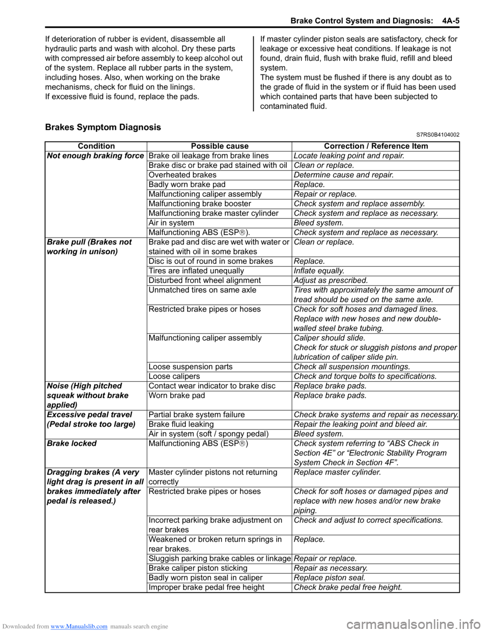
Brakes Symptom DiagnosisS7RS0B4104002
Condition Possible cause Correction / Reference Item
Not enough braking force Brake oil leakage from brake lines Locate leaking point and repair.
Brake disc or brake pad stained with oil Clean or replace.
Overheated brakes Determine cause and repair.
Badly worn brake pad Replace.
Malfunctioning caliper assembly Repair or replace.
Malfunctioning brake booster Check system and replace assembly.
Malfunctioning brake master cylinder Check system and replace as necessary.
Air in system Bleed system.
Malfunctioning ABS (ESP ®). Check system and replace as necessary.
Brake pull (Brakes not
working in unison) Brake pad and disc are wet with water or
stained with oil in some brakes Clean or replace.
Disc is out of round in some brakes Replace.
Tires are inflated unequally Inflate equally.
Disturbed front wheel alignment Adjust as prescribed.
Unmatched tires on same axle Tires with approximately the same amount of
tread should be used on the same axle.
Restricted brake pipes or hoses Check for soft hoses and damaged lines.
Replace with new hoses and new double-
walled steel brake tubing.
Malfunctioning caliper assembly Caliper should slide.
Check for stuck or sluggish pistons and proper
lubrication of caliper slide pin.
Loose suspension parts Check all suspension mountings.
Loose calipers Check and torque bolts to specifications.
Noise (High pitched
squeak without brake
applied) Contact wear indicator to brake disc
Replace brake pads.
Worn brake pad Replace brake pads.
Excessive pedal travel
(Pedal stroke too large) Partial brake system failure
Check brake systems and repair as necessary.
Brake fluid leaking Repair the leaking point and bleed air.
Air in system (soft / spongy pedal) Bleed system.
Brake locked Malfunctioning ABS (ESP®) Check system referri ng to “ABS Check in
Section 4E” or “Electronic Stability Program
System Check in Section 4F”.
Dragging brakes (A very
light drag is present in all
brakes immediately after
pedal is released.) Master cylinder pistons not returning
correctly
Replace master cylinder.
Restricted brake pipes or hoses Check for soft hoses or damaged pipes and
replace with new hoses and/or new brake
piping.
Incorrect parking brake adjustment on
rear brakes Check and adjust to correct specifications.
Weakened or broken return springs in
rear brakes. Replace.
Sluggish parking brake cables or linkage Repair or replace.
Brake caliper piston sticking Repair as necessary.
Badly worn piston seal in caliper Replace piston seal.
Improper brake pedal free height Check brake pedal free height.
Page 504 of 1496
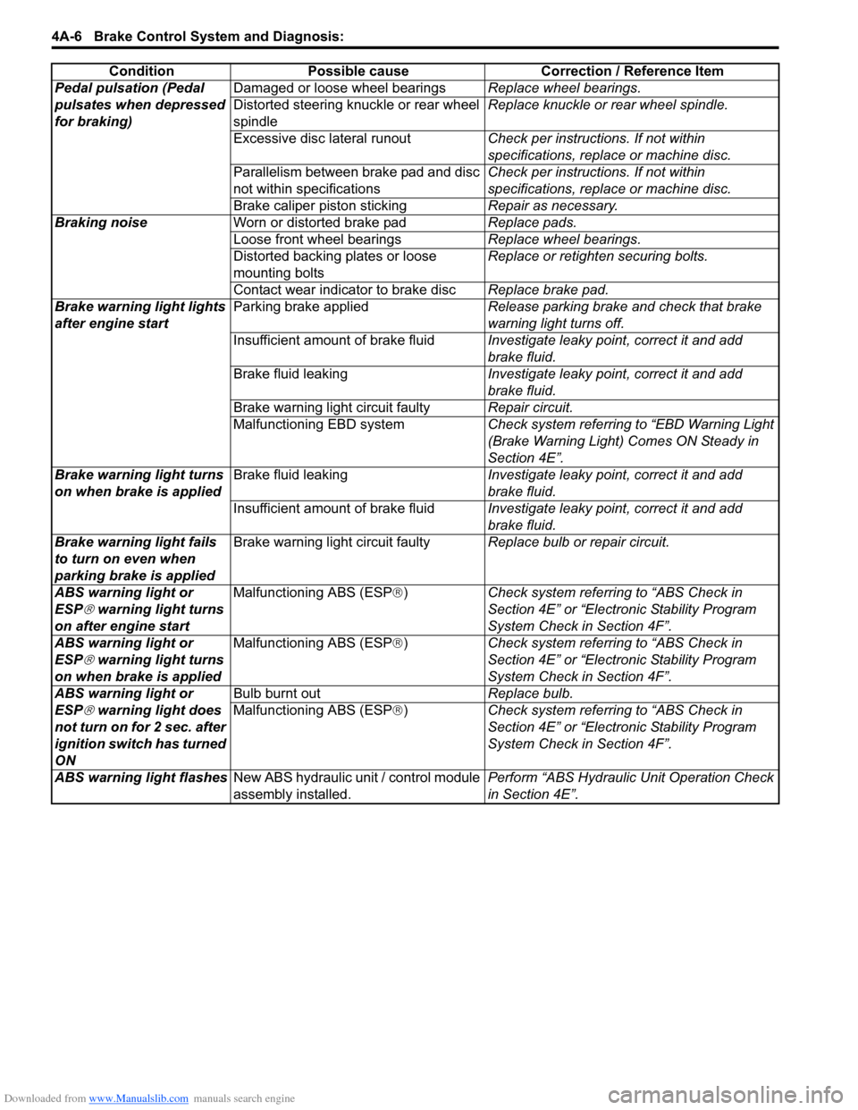
Downloaded from www.Manualslib.com manuals search engine 4A-6 Brake Control System and Diagnosis:
Pedal pulsation (Pedal
pulsates when depressed
for braking)Damaged or loose wheel bearings
Replace wheel bearings.
Distorted steering knuckle or rear wheel
spindle Replace knuckle or rear wheel spindle.
Excessive disc lateral runout Check per instructions. If not within
specifications, replace or machine disc.
Parallelism between brake pad and disc
not within specifications Check per instructions. If not within
specifications, replace or machine disc.
Brake caliper piston sticking Repair as necessary.
Braking noise Worn or distorted brake pad Replace pads.
Loose front wheel bearings Replace wheel bearings.
Distorted backing plates or loose
mounting bolts Replace or retighten securing bolts.
Contact wear indicator to brake disc Replace brake pad.
Brake warning light lights
after engine start Parking brake applied
Release parking brake and check that brake
warning light turns off.
Insufficient amount of brake fluid Investigate leaky point, correct it and add
brake fluid.
Brake fluid leaking Investigate leaky point, correct it and add
brake fluid.
Brake warning light circuit faulty Repair circuit.
Malfunctioning EBD system Check system referring to “EBD Warning Light
(Brake Warning Light) Comes ON Steady in
Section 4E”.
Brake warning light turns
on when brake is applied Brake fluid leaking
Investigate leaky point, correct it and add
brake fluid.
Insufficient amount of brake fluid Investigate leaky point, correct it and add
brake fluid.
Brake warning light fails
to turn on even when
parking brake is applied Brake warning light circuit faulty
Replace bulb or repair circuit.
ABS warning light or
ESP
® warning light turns
on after engine start Malfunctioning ABS (ESP
®) Check system referri ng to “ABS Check in
Section 4E” or “Electronic Stability Program
System Check in Section 4F”.
ABS warning light or
ESP
® warning light turns
on when brake is applied Malfunctioning ABS (ESP
®) Check system referri ng to “ABS Check in
Section 4E” or “Electronic Stability Program
System Check in Section 4F”.
ABS warning light or
ESP
® warning light does
not turn on for 2 sec. after
ignition switch has turned
ON Bulb burnt out
Replace bulb.
Malfunctioning ABS (ESP ®) Check system referri ng to “ABS Check in
Section 4E” or “Electronic Stability Program
System Check in Section 4F”.
ABS warning light flashes New ABS hydraulic unit / control module
assembly installed. Perform “ABS Hydraulic
Unit Operation Check
in Section 4E”.
Condition Possible cause Correction / Reference Item
Page 516 of 1496
Downloaded from www.Manualslib.com manuals search engine 4A-18 Brake Control System and Diagnosis:
10) Check pedal height and play referring to “Brake Pedal Free Height Inspection” and “Brake Pedal
Play Inspection”.
11) Check each installed part for fluid leakage and perform brake test.
12) Evacuate and charge refrigerant by referring to “Evacuating of A/C Syst em” and “Procedure of
Charging” under “Operation Procedure for
Refrigerant Charge in Section 7B” or “Operation
Procedure for Refrigerant Charge in Section 7B”.
Brake Booster Inspection and AdjustmentS7RS0B4106018
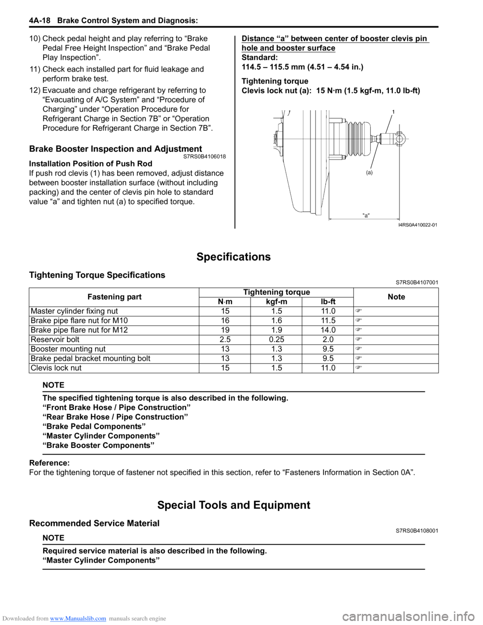
Installation Position of Push Rod
If push rod clevis (1) has b een removed, adjust distance
between booster installation surface (without including
packing) and the center of clevis pin hole to standard
value “a” and tighten nut (a) to specified torque. Distance “a” between center of booster clevis pin
hole and booster surface
Standard:
114.5 – 115.5 mm (4.51 – 4.54 in.)
Tightening torque
Clevis lock nut (a): 15 N·m (1.5 kgf-m, 11.0 lb-ft)
Specifications
Tightening Torque SpecificationsS7RS0B4107001
NOTE
The specified tightening torque is also described in the following.
“Front Brake Hose / Pipe Construction”
“Rear Brake Hose / Pipe Construction”
“Brake Pedal Components”
“Master Cylinder Components”
“Brake Booster Components”
Reference:
For the tightening torque of fastener not specified in this
section, refer to “Fasteners Information in Section 0A”.
Special Tools and Equipment
Recommended Service MaterialS7RS0B4108001
NOTE
Required service material is also described in the following.
“Master Cylinder Components”
I4RS0A410022-01
Fastening part Tightening torque
Note
N ⋅mkgf-mlb-ft
Master cylinder fixing nut 15 1.5 11.0 �)
Brake pipe flare nut for M10 16 1.6 11.5 �)
Brake pipe flare nut for M12 19 1.9 14.0 �)
Reservoir bolt 2.5 0.25 2.0 �)
Booster mounting nut 13 1.3 9.5 �)
Brake pedal bracket mounting bolt 13 1.3 9.5 �)
Clevis lock nut 15 1.5 11.0 �)