Drive SUZUKI SWIFT 2007 2.G Service Workshop Manual
[x] Cancel search | Manufacturer: SUZUKI, Model Year: 2007, Model line: SWIFT, Model: SUZUKI SWIFT 2007 2.GPages: 1496, PDF Size: 34.44 MB
Page 846 of 1496
Downloaded from www.Manualslib.com manuals search engine 5B-32 Manual Transmission/Transaxle:
5th and Reverse Gear Shift Shafts Disassembly
and Assembly
S7RS0B5206023
Disassembly
Disassemble component parts using special tool and
hammer.
Special tool
(A): 09922–85811
Assembly
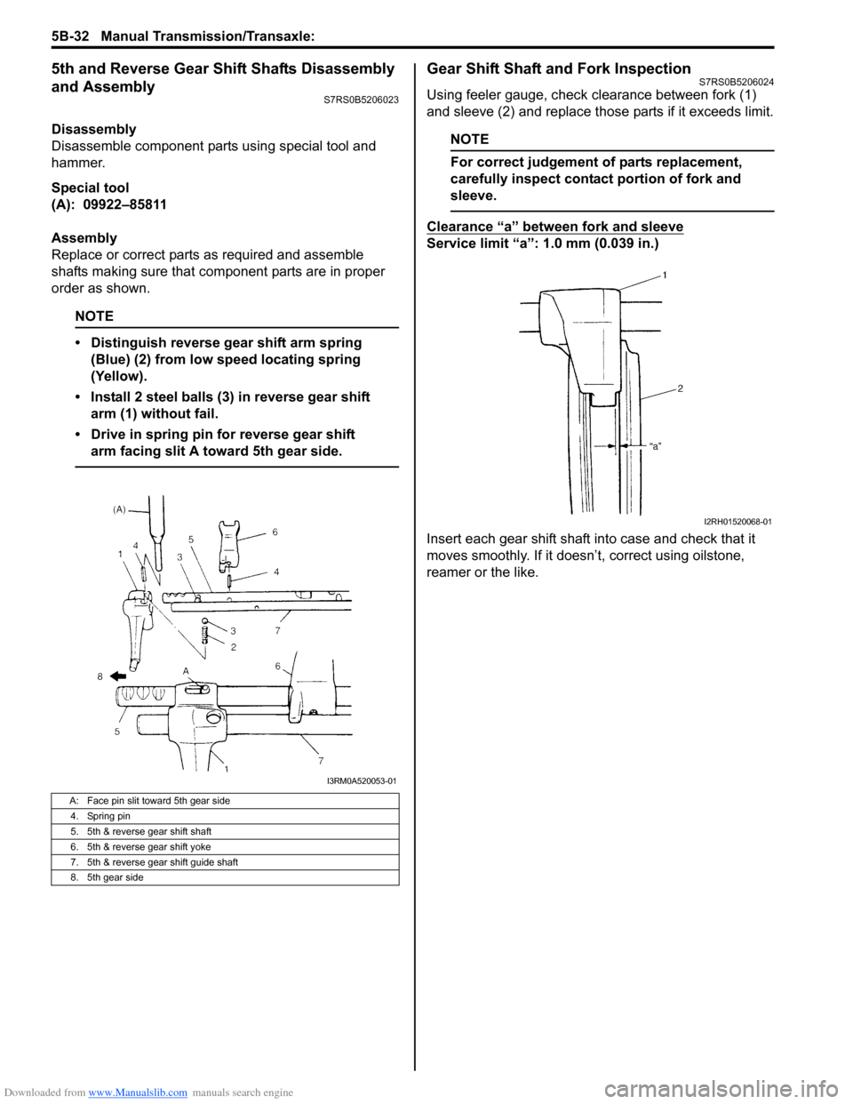
Replace or correct parts as required and assemble
shafts making sure that component parts are in proper
order as shown.
NOTE
• Distinguish reverse gear shift arm spring (Blue) (2) from low speed locating spring
(Yellow).
• Install 2 steel balls (3) in reverse gear shift arm (1) without fail.
• Drive in spring pin for reverse gear shift arm facing slit A toward 5th gear side.
Gear Shift Shaft and Fork InspectionS7RS0B5206024
Using feeler gauge, check clearance between fork (1)
and sleeve (2) and replace those parts if it exceeds limit.
NOTE
For correct judgement of parts replacement,
carefully inspect contact portion of fork and
sleeve.
Clearance “a” between fork and sleeve
Service limit “a”: 1.0 mm (0.039 in.)
Insert each gear shift shaft into case and check that it
moves smoothly. If it doesn’t, correct using oilstone,
reamer or the like.
A: Face pin slit toward 5th gear side
4. Spring pin
5. 5th & reverse gear shift shaft
6. 5th & reverse gear shift yoke
7. 5th & reverse gear shift guide shaft
8. 5th gear side
I3RM0A520053-01
I2RH01520068-01
Page 847 of 1496
Downloaded from www.Manualslib.com manuals search engine Manual Transmission/Transaxle: 5B-33
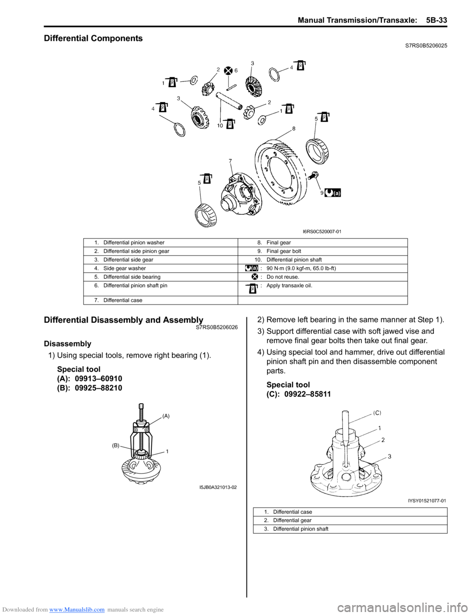
Differential ComponentsS7RS0B5206025
Differential Disassembly and AssemblyS7RS0B5206026
Disassembly1) Using special tools, remove right bearing (1).
Special tool
(A): 09913–60910
(B): 09925–88210 2) Remove left bearing in the same manner at Step 1).
3) Support differential case with soft jawed vise and
remove final gear bolts then take out final gear.
4) Using special tool and hammer, drive out differential pinion shaft pin and then disassemble component
parts.
Special tool
(C): 09922–85811
1. Differential pinion washer 8. Final gear
2. Differential side pinion gear 9. Final gear bolt
3. Differential side gear 10. Differential pinion shaft
4. Side gear washer : 90 N⋅m (9.0 kgf-m, 65.0 lb-ft)
5. Differential side bearing : Do not reuse.
6. Differential pinion shaft pin : Apply transaxle oil.
7. Differential case
I6RS0C520007-01
1(B)
(A)
I5JB0A321013-02
1. Differential case
2. Differential gear
3. Differential pinion shaft
IYSY01521077-01
Page 848 of 1496
Downloaded from www.Manualslib.com manuals search engine 5B-34 Manual Transmission/Transaxle:
Assembly
Judging from abnormality noted before disassembly and
what is found through visual check of component parts
after disassembly, prepare replacing parts and proceed
to reassembly. Make sure that all parts are clean.
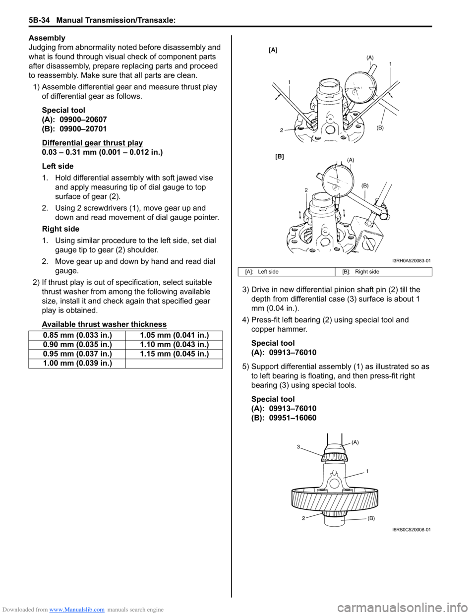
1) Assemble differential gear and measure thrust play
of differential gear as follows.
Special tool
(A): 09900–20607
(B): 09900–20701
Differential gear thrust play
0.03 – 0.31 mm (0.001 – 0.012 in.)
Left side
1. Hold differential assembly with soft jawed vise and apply measuring tip of dial gauge to top
surface of gear (2).
2. Using 2 screwdrivers (1), move gear up and down and read movement of dial gauge pointer.
Right side
1. Using similar procedure to the left side, set dial gauge tip to gear (2) shoulder.
2. Move gear up and down by hand and read dial gauge.
2) If thrust play is out of sp ecification, select suitable
thrust washer from among the following available
size, install it and check again that specified gear
play is obtained.
Available thrust washer thickness
3) Drive in new differential pinion shaft pin (2) till the depth from differential case (3) surface is about 1
mm (0.04 in.).
4) Press-fit left bearing (2) using special tool and copper hammer.
Special tool
(A): 09913–76010
5) Support differential assembly (1) as illustrated so as to left bearing is floating , and then press-fit right
bearing (3) using special tools.
Special tool
(A): 09913–76010
(B): 09951–16060
0.85 mm (0.033 in.) 1.05 mm (0.041 in.)
0.90 mm (0.035 in.) 1.10 mm (0.043 in.)
0.95 mm (0.037 in.) 1.15 mm (0.045 in.)
1.00 mm (0.039 in.)
[A]: Left side
[B]: Right side
I3RH0A520083-01
1
(A)
3
2 (B)
I6RS0C520008-01
Page 853 of 1496
Downloaded from www.Manualslib.com manuals search engine Clutch: 5C-1
Transmission / Transaxle
Clutch
General Description
Clutch ConstructionS7RS0B5301001
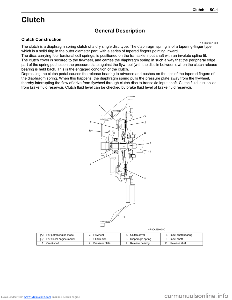
The clutch is a diaphragm spring clutch of a dry single disc type. The diaphragm spring is of a tapering-finger type,
which is a solid ring in the outer diameter part, with a series of tapered fingers pointing inward.
The disc, carrying four torsional coil springs, is positione d on the transaxle input shaft with an involute spline fit.
The clutch cover is secured to the flywheel, and carries the diaphragm spring in such a way that the peripheral edge
part of the spring pushes on the pressure plate against the flywheel (with the disc in between), when the clutch release
bearing is held back. This is the engaged condition of the clutch.
Depressing the clutch pedal c auses the release bearing to advance and pushes on the tips of the tapered fingers of
the diaphragm spring. When this happens, the diaphragm sp ring pulls the pressure plate away from the flywheel,
thereby interrupting the flow of drive from flywheel through clutch disc to transaxle input shaft. Clutch fluid is supplied
from brake fluid reservoir. Clutch fluid level can be checked by brake fluid level of brake fluid reservoir.
[A]: For petrol engine model2. Flywheel5. Clutch cover 8. Input shaft bearing
[B]: For diesel engine model 3. Clutch disc6. Diaphragm spring 9. Input shaft
1. Crankshaft 4. Pressure plate7. Release bearing 10. Release shaft
I4RS0A530001-01
Page 863 of 1496
Downloaded from www.Manualslib.com manuals search engine Clutch: 5C-11
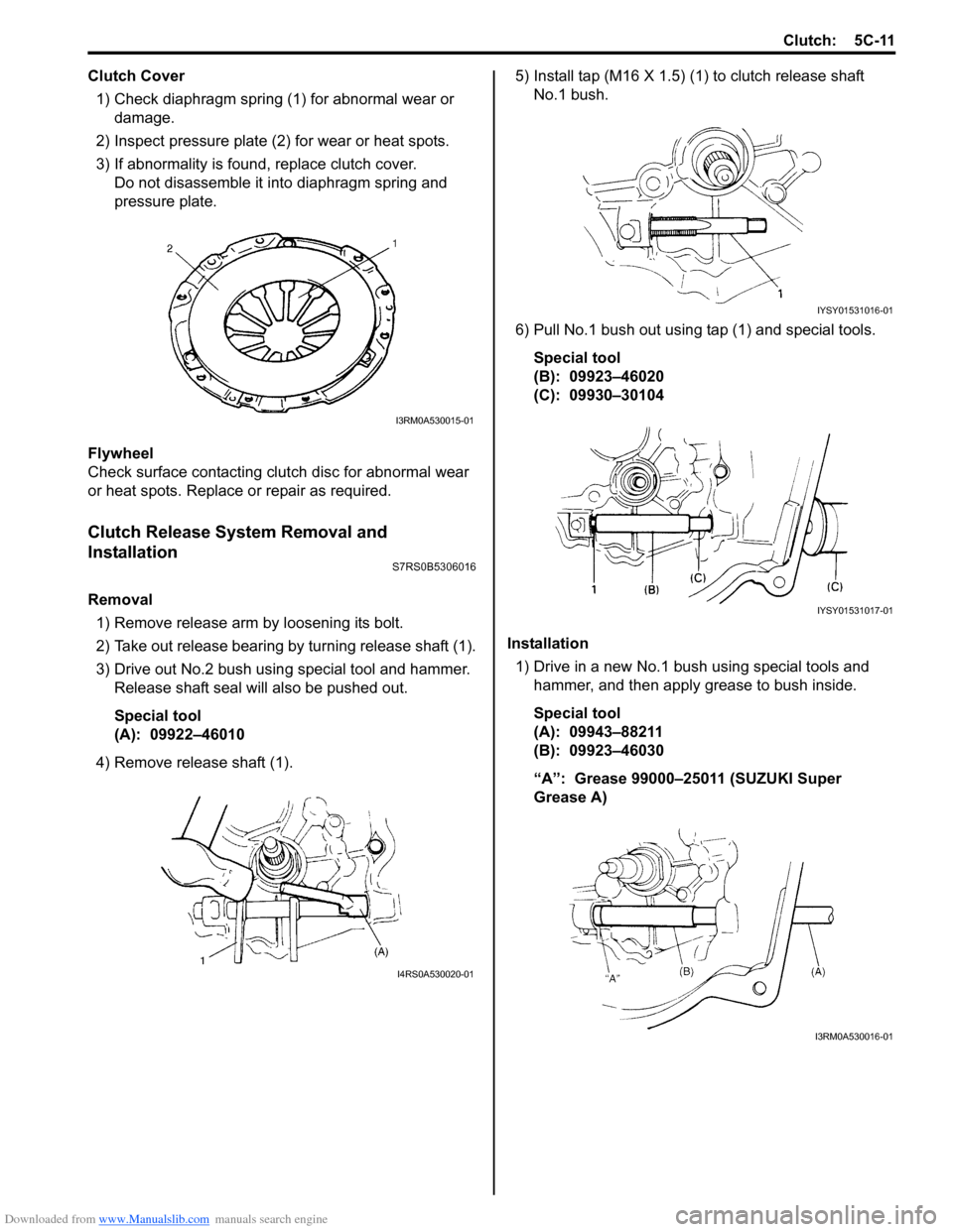
Clutch Cover1) Check diaphragm spring (1) for abnormal wear or damage.
2) Inspect pressure plate (2) for wear or heat spots.
3) If abnormality is found, replace clutch cover. Do not disassemble it into diaphragm spring and
pressure plate.
Flywheel
Check surface contacting clutch disc for abnormal wear
or heat spots. Replace or repair as required.
Clutch Release System Removal and
Installation
S7RS0B5306016
Removal 1) Remove release arm by loosening its bolt.
2) Take out release bearing by turning release shaft (1).
3) Drive out No.2 bush usin g special tool and hammer.
Release shaft seal will also be pushed out.
Special tool
(A): 09922–46010
4) Remove release shaft (1). 5) Install tap (M16 X 1.5) (1) to clutch release shaft
No.1 bush.
6) Pull No.1 bush out using tap (1) and special tools. Special tool
(B): 09923–46020
(C): 09930–30104
Installation 1) Drive in a new No.1 bush using special tools and
hammer, and then apply grease to bush inside.
Special tool
(A): 09943–88211
(B): 09923–46030
“A”: Grease 99000–25011 (SUZUKI Super
Grease A)
I3RM0A530015-01
I4RS0A530020-01
IYSY01531016-01
IYSY01531017-01
I3RM0A530016-01
Page 872 of 1496
Downloaded from www.Manualslib.com manuals search engine 6B-1 Steering Wheel and Column:
Steeri ng
Steering Wheel and Column
Precautions
Service Precautions of Steering Wheel and
Column
S7RS0B6200001
For service precautions, refer to “Precautions on Service
and Diagnosis of Air Bag System in Section 8B”.
Service and Diagnosis
For diagnosis and servicing, refer to “Precautions on
Service and Diagnosis of Air Bag System in Section 8B”.
Disabling Air Bag System
For disabling air bag system, refer to “Disabling Air Bag
System in Section 8B”. Enabling Air Bag System
For enabling air bag system, refer to “Enabling Air Bag
System in Section 8B”.
Handling and Storage
For handling and storage, refer to “Precautions on
Handling and Storage of Air Bag System Components in
Section 8B”.
Disposal
For disposal, refer to “Prec
autions on Disposal of Air
Bag and Seat Belt Pretensioner in Section 8B”.
General Description
Steering Wheel and Column ConstructionS7RS0B6201001
This double tube type steering column has the following three important features in addition to the steering function:
• The column is energy absorbing, desig ned to compress in a front-end collision.
• The ignition switch and lock are mounted conveniently on this column.
• With the column mounted lock, the ignition and steering op erations can be locked to inhibit theft of the vehicle.
To insure the energy absorbing action, it is important th at only the specified screws, bolts and nuts be used as
designated, and that they are tightened to the specified torque. When the column assembly is removed from the
vehicle, special care must be taken in handling it. Use of a steering wheel puller or a sharp blow on the end of the
steering shaft, leaning on the assembly, or dropping the a ssembly could shear the plastic shear pins which maintain
column length and position.
The driver air bag (inflator) module is one of the supplemental restraint (air bag) system components and is mounted
to the center of the steering wheel. During certain frontal crashes, the air bag system supplements the restraint of the
driver’s and passenger’s seat belts by deploying the air b ags. The air bag (inflator) module should be handled with
care to prevent accidental deployment. When servicing, be sure to observe “Precautions on Service and Diagnosis of
Air Bag System in Section 8B”.
Page 874 of 1496
Downloaded from www.Manualslib.com manuals search engine 6B-3 Steering Wheel and Column:
Repair Instructions
Steering Wheel and Column ConstructionS7RS0B6206001
21
2 3
4
7
5
6
8
9
11
12 10
15
(a)
(b)
13(c)
14
(d)
16
I4RS0B620001-04
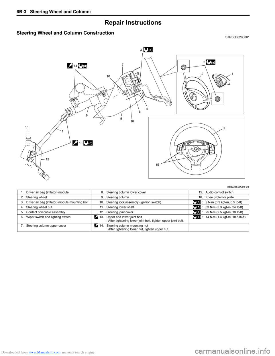
1. Driver air bag (inflator) module
8. Steering column lower cover 15. Audio control switch
2. Steering wheel 9. Steering column 16. Knee protector plate
3. Driver air bag (inflator) module mounting bolt 10. Steering lock assembly (ignition switch) : 9 N⋅m (0.9 kgf-m, 6.5 lb-ft)
4. Steering wheel nut 11. Steering lower shaft : 33 N⋅m (3.3 kgf-m, 24 lb-ft)
5. Contact coil cable assembly 12. Steering joint cover : 25 N⋅m (2.5 kgf-m, 18 lb-ft)
6. Wiper switch and lighting switch 13. Upper and lower joint bolt
: After tightening lower joint bolt, tighten upper joint bolt. : 14 N
⋅m (1.4 kgf-m, 10.5 lb-ft)
7. Steering column upper cover 14. Steering column mounting nut
: After tightening lower nut, tighten upper nut.
Page 875 of 1496
Downloaded from www.Manualslib.com manuals search engine Steering Wheel and Column: 6B-4
Steering Wheel Removal and InstallationS7RS0B6206002
CAUTION!
Do not turn the contact coil more than
allowable number of turns (about two and a
half turns from the center position clockwise
or counterclockwise respectively) with
steering wheel removed, or coil will break.
Removal
CAUTION!
Do not hammer the end of the shaft.
Hammering it will loosen the plastic shear
pins which maintain the column length and
impair the collapsible design of the column.
1) Disconnect negative (–) cable at battery.
2) Disable air bag system referring to “Disabling Air
Bag System in Section 8B”.
3) Remove driver air bag (inflator) module from steering wheel. Refer to “Driver Air Bag (Inflator)
Module Removal and Installation in Section 8B”.
4) Disconnect horn connector and audio control switch connector, if equipped.
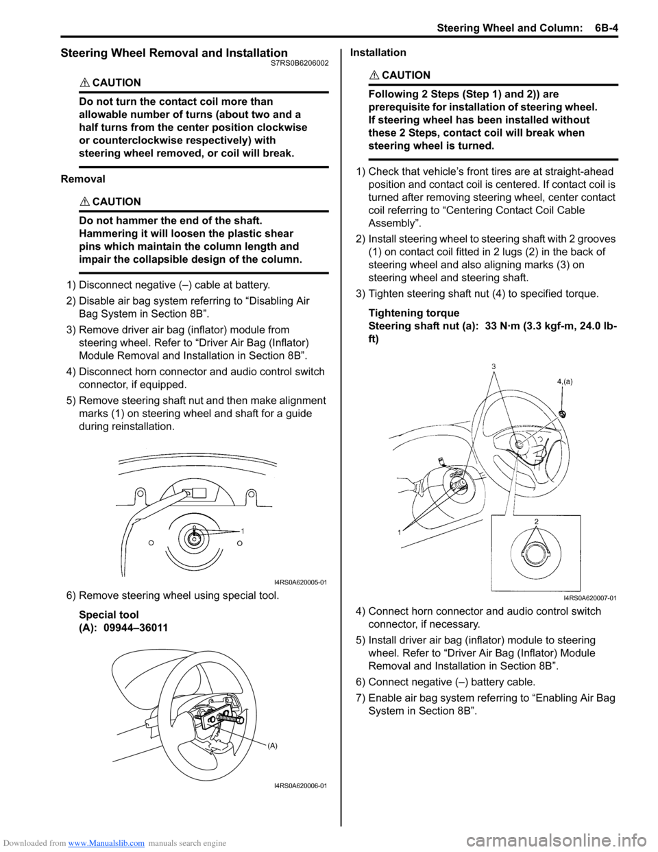
5) Remove steering shaft nut and then make alignment marks (1) on steering wheel and shaft for a guide
during reinstallation.
6) Remove steering wheel using special tool. Special tool
(A): 09944–36011 Installation
CAUTION!
Following 2 Steps (Step 1) and 2)) are
prerequisite for installation of steering wheel.
If steering wheel has
been installed without
these 2 Steps, contact coil will break when
steering wheel is turned.
1) Check that vehicle’s front tires are at straight-ahead position and contact coil is centered. If contact coil is
turned after removing steering wheel, center contact
coil referring to “Centering Contact Coil Cable
Assembly”.
2) Install steering wheel to steering shaft with 2 grooves (1) on contact coil fitted in 2 lugs (2) in the back of
steering wheel and also aligning marks (3) on
steering wheel and steering shaft.
3) Tighten steering shaft nut (4) to specified torque.
Tightening torque
Steering shaft nut (a): 33 N·m (3.3 kgf-m, 24.0 lb-
ft)
4) Connect horn connector and audio control switch connector, if necessary.
5) Install driver air bag (inflator) module to steering wheel. Refer to “Driver Air Bag (Inflator) Module
Removal and Installati on in Section 8B”.
6) Connect negative (–) battery cable.
7) Enable air bag system refe rring to “Enabling Air Bag
System in Section 8B”.
I4RS0A620005-01
(A)
I4RS0A620006-01
I4RS0A620007-01
Page 885 of 1496
Downloaded from www.Manualslib.com manuals search engine Power Assisted Steering System: 6C-3
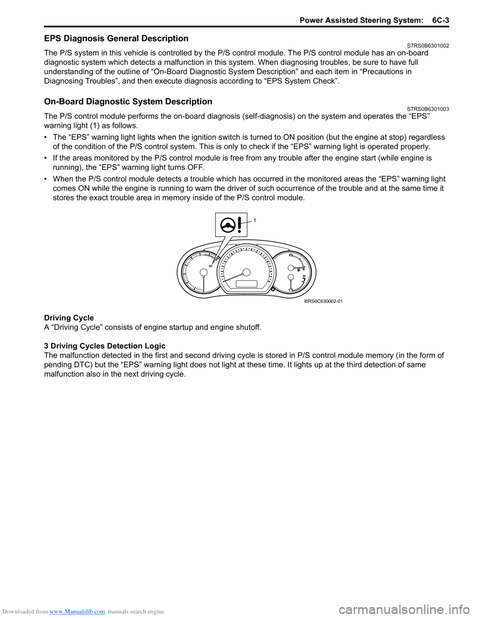
EPS Diagnosis General DescriptionS7RS0B6301002
The P/S system in this vehicle is controlled by the P/S control module. T he P/S control module has an on-board
diagnostic system which detects a malfunction in this system. When diagnosing troubles, be sure to have full
understanding of the outline of “On-Board Diagnostic Sy stem Description” and each item in “Precautions in
Diagnosing Troubles”, and then execute diagnosis according to “EPS System Check”.
On-Board Diagnostic System DescriptionS7RS0B6301003
The P/S control module performs the on -board diagnosis (self-diagnosis) on the system and operates the “EPS”
warning light (1) as follows.
• The “EPS” warning light lights when the ignition switch is turned to ON position (but the engine at stop) regardless
of the condition of the P/S co ntrol system. This is only to check if the “EPS” warning light is operated properly.
• If the areas monitored by the P/S control module is free from any trouble after the engine start (while engine is
running), the “EPS” warning light turns OFF.
• When the P/S control module detects a trouble which has occurred in th e monitored areas the “EPS” warning light
comes ON while the engine is running to warn the driver of such occurrence of the trouble and at the same time it
stores the exact trouble area in memory inside of the P/S control module.
Driving Cycle
A “Driving Cycle” consists of en gine startup and engine shutoff.
3 Driving Cycles Detection Logic
The malfunction detected in the first and second driving cycl e is stored in P/S control module memory (in the form of
pending DTC) but the “EPS” wa rning light does not light at these time. It lights up at t he third detection of same
malfunction also in the next driving cycle.
1
I6RS0C630002-01
Page 887 of 1496
Downloaded from www.Manualslib.com manuals search engine Power Assisted Steering System: 6C-5
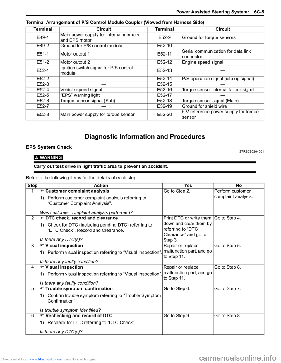
Terminal Arrangement of P/S Control Module Coupler (Viewed from Harness Side)
Diagnostic Information and Procedures
EPS System CheckS7RS0B6304001
WARNING!
Carry out test drive in light traffic area to prevent an accident.
Refer to the following items for the details of each step.Terminal Circuit Terminal Circuit
E49-1 Main power supply for internal memory
and EPS motor E52-9 Ground for torque sensors
E49-2 Ground for P/S control module E52-10 —
E51-1 Motor output 1 E52-11 Serial communication for data link
connector
E51-2 Motor output 2 E52-12 Engine speed signal
E52-1 Ignition switch signal for P/S control
module E52-13 —
E52-2 — E52-14 P/S operation signal (idle up signal)
E52-3 — E52-15 —
E52-4 Vehicle speed signal E52-16 Torque sensor internal failure signal
E52-5 “EPS” warning light E52-17 —
E52-6 Torque sensor signal (Sub) E52-18 Torque sensor signal (Main)
E52-7 — E52-19 Ground for shield wire
E52-8 Main power supply for torque sensor E52-20 5 V reference power supply for torque
sensor
Step
Action YesNo
1 �) Customer complaint analysis
1) Perform customer complaint analysis referring to “Customer Complaint Analysis”.
Was customer complaint analysis performed? Go to Step 2.
Perform customer
complaint analysis.
2 �) DTC check, record and clearance
1) Check for DTC (including pending DTC) referring to “DTC Check”, Record and Clearance.
Is there any DTC(s)? Print DTC or write them
down and clear them by
referring to “DTC
Clearance” and go to
St ep 3 .Go to Step 4.
3 �) Visual inspection
1) Perform visual inspection referring to “Visual Inspection”.
Is there any faulty condition? Repair or replace
malfunction part, and go
to Step 11.
Go to Step 5.
4 �) Visual inspection
1) Perform visual inspection referring to “Visual Inspection”.
Is there any faulty condition? Repair or replace
malfunction part, and go
to Step 11.
Go to Step 8.
5 �) Trouble symptom confirmation
1) Confirm trouble symptom referring to “Trouble Symptom Confirmation”.
Is trouble symptom identified? Go to Step 6.
Go to Step 7.
6 �) Rechecking and record of DTC
1) Recheck for DTC referring to “DTC Check”.
Is there any DTC(s)? Go to Step 9.
Go to Step 8.