Camshaft Position SUZUKI SWIFT 2007 2.G Service Owner's Manual
[x] Cancel search | Manufacturer: SUZUKI, Model Year: 2007, Model line: SWIFT, Model: SUZUKI SWIFT 2007 2.GPages: 1496, PDF Size: 34.44 MB
Page 163 of 1496
Downloaded from www.Manualslib.com manuals search engine Engine General Information and Diagnosis: 1A-113
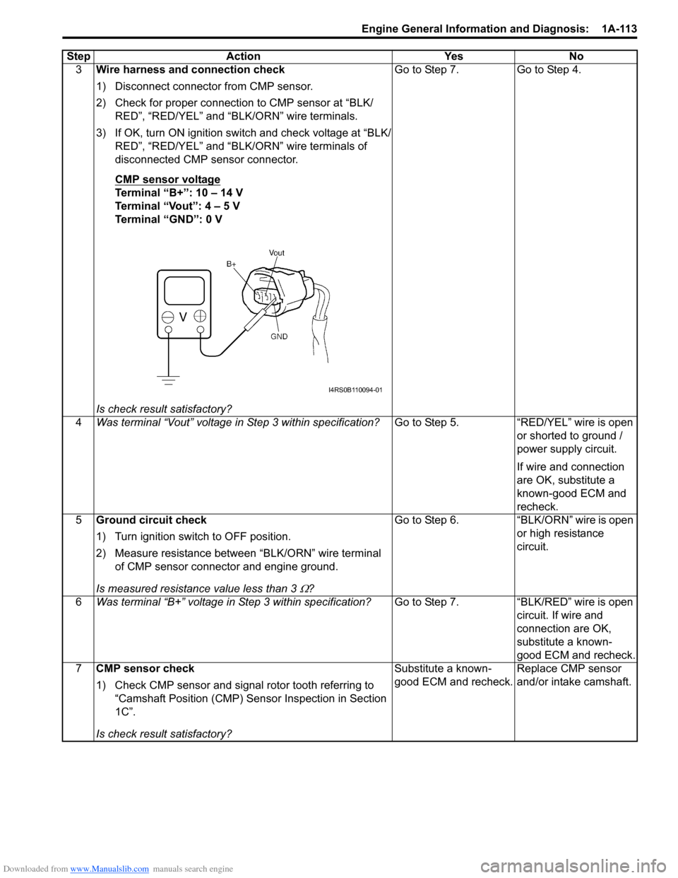
3Wire harness and connection check
1) Disconnect connector from CMP sensor.
2) Check for proper connection to CMP sensor at “BLK/
RED”, “RED/YEL” and “B LK/ORN” wire terminals.
3) If OK, turn ON ignition switch and check voltage at “BLK/ RED”, “RED/YEL” and “BLK/ORN” wire terminals of
disconnected CMP sensor connector.
CMP sensor voltage
Terminal “B+”: 10 – 14 V
Terminal “Vout”: 4 – 5 V
Terminal “GND”: 0 V
Is check result satisfactory? Go to Step 7. Go to Step 4.
4 Was terminal “Vout” voltage in Step 3 within specification? Go to Step 5. “RED/YEL” wire is open
or shorted to ground /
power supply circuit.
If wire and connection
are OK, substitute a
known-good ECM and
recheck.
5 Ground circuit check
1) Turn ignition switch to OFF position.
2) Measure resistance between “BLK/ORN” wire terminal
of CMP sensor connector and engine ground.
Is measured resistance value less than 3
Ω? Go to Step 6. “BLK/ORN” wire is open
or high resistance
circuit.
6 Was terminal “B+” voltage in Step 3 within specification? Go to Step 7. “BLK/RED” wire is open
circuit. If wire and
connection are OK,
substitute a known-
good ECM and recheck.
7 CMP sensor check
1) Check CMP sensor and signal rotor tooth referring to
“Camshaft Position (CMP) Sensor Inspection in Section
1C”.
Is check result satisfactory? Substitute a known-
good ECM and recheck.
Replace CMP sensor
and/or intake camshaft.
Step Action Yes No
I4RS0B110094-01
Page 228 of 1496
Downloaded from www.Manualslib.com manuals search engine 1A-178 Engine General Information and Diagnosis:
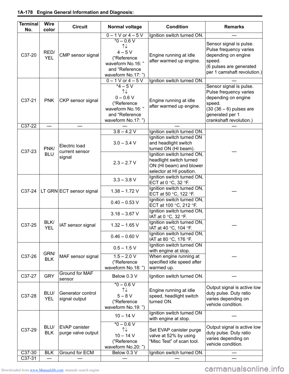
C37-20RED/
YEL CMP sensor signal 0 – 1 V or 4 – 5 V Ignition switch turned ON. —
*0 – 0.6 V↑↓
4 – 5 V
(“Reference
waveform No.16: ” and “Reference
waveform No.17: ”) Engine running at idle
after warmed up engine.
Sensor signal is pulse.
Pulse frequency varies
depending on engine
speed.
(6 pulses are generated
per 1 camshaft revolution.)
C37-21 PNK CKP sensor signal 0 – 1 V or 4 – 5 V Ignition switch turned ON. —
*4 – 5 V↑↓
0 – 0.6 V
(“Reference
waveform No.16: ” and “Reference
waveform No.17: ”) Engine running at idle
after warmed up engine. Sensor signal is pulse.
Pulse frequency varies
depending on engine
speed.
(30 (36 – 6) pulses are
generated per 1
crankshaft revolution.)
C37-22 — — — — —
C37-23 PNK/
BLU Electric load
current sensor
signal 3.8 – 4.2 V Ignition switch turned ON.
—
3.0 – 3.4 V
Ignition switch turned ON
and headlight switch
turned ON (HI beam).
2.3 – 2.7 V Ignition switch turned ON,
headlight switch turned
ON (HI beam) and blower
selector at HI position.
C37-24 LT GRN ECT sensor signal 3.3 – 3.8 V
Ignition switch turned ON,
ECT at 0
°C, 32 °F.
—
1.38 – 1.72 V Ignition switch turned ON,
ECT at 50
°C, 122 °F.
0.40 – 0.53 V Ignition switch turned ON,
ECT at 100
°C, 212 °F.
C37-25 BLK/
YEL IAT sensor signal 3.18 – 3.67 V
Ignition switch turned ON,
IAT at 0
°C, 32 °F.
—
1.32 – 1.65 V Ignition switch turned ON,
IAT at 40
°C, 104 °F.
0.46 – 0.60 V Ignition switch turned ON,
IAT at 80
°C, 176 °F.
C37-26 GRN/
BLK MAF sensor signal 0.5 – 1.5 V
Ignition switch turned ON
with engine at stop.
—
1.5 – 2.0 V
(“Reference
waveform No.18: ”) Wh
en engine running at
specified idle speed after
warmed up.
C37-27 GRY Ground for MAF
sensor Below 0.3 V Ignition switch turned ON.
—
C37-28 BLU/
YEL Generator control
signal output *0 – 0.6 V
↑↓
5 – 8 V
(“Reference
waveform No.19: ”) Engine running at idle
speed, headlight switch
turned ON.
Output signal is active low
duty pulse. Duty ratio
varies depending on
vehicle condition.
C37-29 BLU/
BLK EVAP canister
purge valve output 10 – 14 V
Ignition switch turned ON
with engine at stop. —
*0 – 0.6 V ↑↓
10 – 14 V
(“Reference
waveform No.20: ”) Set EVAP canister purge
valve at 52% by using
“Misc Test” of scan tool.
Output signal is active low
duty pulse. Duty ratio
varies depending on
vehicle condition.
C37-30 BLK Ground for ECM Below 0.3 V Ignition switch turned ON. —
C37-31 — —— — —
Terminal
No. Wire
color Circuit Normal voltage
ConditionRemarks
Page 280 of 1496
Downloaded from www.Manualslib.com manuals search engine 1C-8 Engine Electrical Devices:
Installation
Reverse removal procedure noting the following.
• Tighten heated oxygen sensor to specified torque.Tightening torque
Heated oxygen sensor (a): 45 N·m (4.5 kgf-m,
32.5 lb-ft)
• Install exhaust manifold referring to “Exhaust Manifold Removal and Installation in Section 1K”, if removed.
• Connect connector of heated oxygen sensor and clamp wire harness securely.
• After installing heated oxygen sensor, start engine and check that no exhaust gas leakage exists.
CMP Sensor Removal and InstallationS7RS0B1306012
Removal
1) Disconnect negative (–) cable at battery.
2) Disconnect connector from CMP sensor.
3) Remove CMP sensor from cylinder head.
Installation 1) Install CMP sensor to cylinder head.
Tightening torque
CMP sensor bolt (a): 10 N·m (1.0 kgf-m, 7.5 lb-ft)
2) Connect connector to CMP sensor securely.
3) Connect negative (–) cable to battery.
Camshaft Position (CMP) Sensor InspectionS7RS0B1306013
Visual check
• Check that O-ring is free from damage.
• Check that end face of sensor and signal rotor tooth are free from any metal particles and damage.
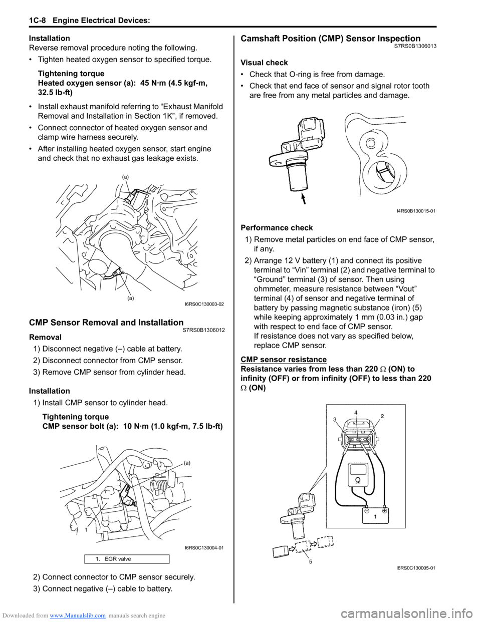
Performance check 1) Remove metal particles on end face of CMP sensor, if any.
2) Arrange 12 V battery (1) and connect its positive terminal to “Vin” terminal (2) and negative terminal to
“Ground” terminal (3) of sensor. Then using
ohmmeter, measure resistance between “Vout”
terminal (4) of sensor and negative terminal of
battery by passing magnetic substance (iron) (5)
while keeping approximately 1 mm (0.03 in.) gap
with respect to end face of CMP sensor.
If resistance does not vary as specified below,
replace CMP sensor.
CMP sensor resistance
Resistance varies from less than 220 Ω (ON) to
infinity (OFF) or from infinity (OFF) to less than 220
Ω (ON)
1. EGR valve
(a)
(a)
I6RS0C130003-02
I6RS0C130004-01
I4RS0B130015-01
I6RS0C130005-01
Page 287 of 1496
Downloaded from www.Manualslib.com manuals search engine Engine Mechanical: 1D-2
Camshaft Position Control (VVT Variable Valve Timing) System DescriptionS7RS0B1401002
System Description
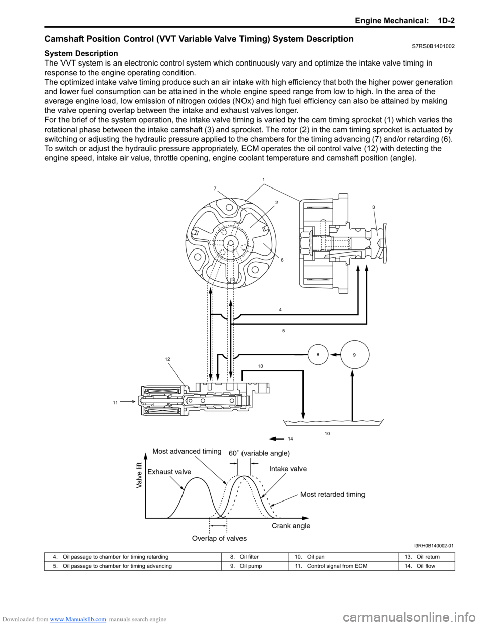
The VVT system is an electronic control system which continuously vary and optimize the intake valve timing in
response to the engine operating condition.
The optimized intake valve timing produce such an air intake with high efficiency that both the higher power generation
and lower fuel consumption can be attained in the whole engine speed range from low to high. In the area of the
average engine load, low emission of nitrogen oxides (NOx) and high fuel efficiency can also be attained by making
the valve opening overlap between the intake and exhaust valves longer.
For the brief of the system operation, the intake valve timing is varied by the cam timing sprocket (1) which varies the
rotational phase between the intake camshaft (3) and sprocket . The rotor (2) in the cam timing sprocket is actuated by
switching or adjusting the hydraulic pressure applied to the chambers for the timing advancing (7) and/or retarding (6).
To switch or adjust the hydraulic pressure appropriately, ECM operates the oil control valve (12) with detecting the
engine speed, intake air value, throttle opening, engine coolant temperature and camshaft position (angle).
1
4
5
13
10
89
2
7
6
12
11
3
14
60� (variable angle)
Most retarded timing
Most advanced timing
Exhaust valve Intake valve
Crank angle
Overlap of valves
Valve lift
I3RH0B140002-01
4. Oil passage to chamber for timing retarding 8. Oil filter10. Oil pan 13. Oil return
5. Oil passage to chamber for timing advancing 9. Oil pump11. Control signal from ECM 14. Oil flow
Page 288 of 1496
Downloaded from www.Manualslib.com manuals search engine 1D-3 Engine Mechanical:
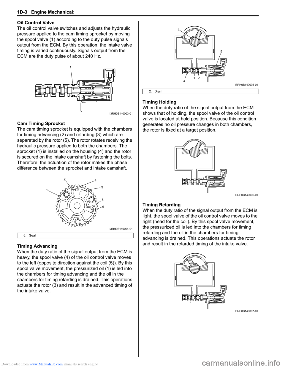
Oil Control Valve
The oil control valve switches and adjusts the hydraulic
pressure applied to the cam timing sprocket by moving
the spool valve (1) according to the duty pulse signals
output from the ECM. By this operation, the intake valve
timing is varied continuously. Signals output from the
ECM are the duty pulse of about 240 Hz.
Cam Timing Sprocket
The cam timing sprocket is equipped with the chambers
for timing advancing (2) and retarding (3) which are
separated by the rotor (5). The rotor rotates receiving the
hydraulic pressure applied to both the chambers. The
sprocket (1) is installed on the housing (4) and the rotor
is secured on the intake camshaft by fastening the bolts.
Therefore, the actuation of the rotor makes the phase
difference between the sprocket and intake camshaft.
Timing Advancing
When the duty ratio of the signal output from the ECM is
heavy, the spool valve (4) of the oil control valve moves
to the left (opposite direction against the coil (5)). By this
spool valve movement, the pressurized oil (1) is led into
the chambers for timing advancing and the oil in the
chambers for timing retarding is drained. This operations
actuate the rotor (3) and result in the advanced timing of
the intake valve. Timing Holding
When the duty ratio of the si
gnal output from the ECM
shows that of holding, the sp ool valve of the oil control
valve is located at hold posi tion. Because this condition
generates no oil pressure changes in both chambers,
the rotor is fixed at a target position.
Timing Retarding
When the duty ratio of the sig nal output from the ECM is
light, the spool valve of the o il control valve moves to the
right (head for the coil). By this spool valve movement,
the pressurized oil is led into the chambers for timing
retarding and the oil in the chambers for timing
advancing is drained. This operations actuate the rotor
and result in the retarded timing of the intake valve.
6. Seal
1
I3RH0B140003-01
1 2
3
4
56
I3RH0B140004-01
2. Drain
12
5
4
3
I3RH0B140005-01
I3RH0B140006-01
I3RH0B140007-01
Page 292 of 1496
Downloaded from www.Manualslib.com manuals search engine 1D-7 Engine Mechanical:
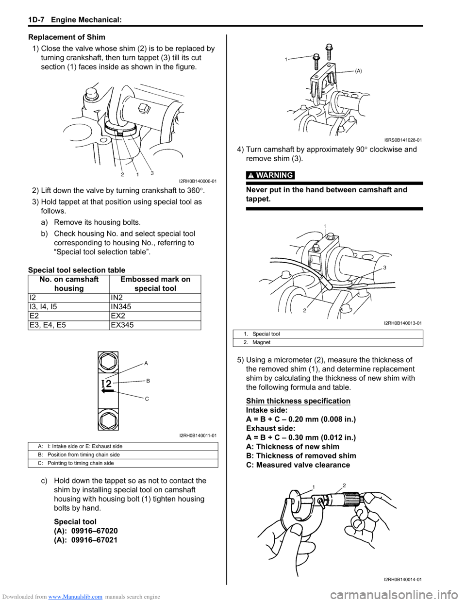
Replacement of Shim1) Close the valve whose shim (2) is to be replaced by turning crankshaft, then tu rn tappet (3) till its cut
section (1) faces inside as shown in the figure.
2) Lift down the valve by turning crankshaft to 360° .
3) Hold tappet at that position using special tool as follows.
a) Remove its housing bolts.
b) Check housing No. and select special tool corresponding to housing No., referring to
“Special tool selection table”.
Special tool selection table
c) Hold down the tappet so as not to contact the shim by installing special tool on camshaft
housing with housing bolt (1) tighten housing
bolts by hand.
Special tool
(A): 09916–67020
(A): 09916–67021 4) Turn camshaft by approximately 90
° clockwise and
remove shim (3).
WARNING!
Never put in the hand between camshaft and
tappet.
5) Using a micrometer (2), measure the thickness of the removed shim (1), and determine replacement
shim by calculating the thickness of new shim with
the following formula and table.
Shim thickness specification
Intake side:
A = B + C – 0.20 mm (0.008 in.)
Exhaust side:
A = B + C – 0.30 mm (0.012 in.)
A: Thickness of new shim
B: Thickness of removed shim
C: Measured valve clearance
No. on camshaft
housing Embossed mark on
special tool
I2 IN2
I3, I4, I5 IN345
E2 EX2
E3, E4, E5 EX345
A: I: Intake side or E: Exhaust side
B: Position from timing chain side
C: Pointing to timing chain side
I2RH0B140006-01
I2RH0B140011-01
1. Special tool
2. Magnet
I6RS0B141028-01
I2RH0B140013-01
I2RH0B140014-01
Page 310 of 1496
Downloaded from www.Manualslib.com manuals search engine 1D-25 Engine Mechanical:
Timing Chain and Chain Tensioner Removal
and Installation
S7RS0B1406018
Removal
CAUTION!
After timing chain is removed, never turn
crankshaft and camshafts independently
more than its allowable turning range
described in “Installation”.
If turned, interferen ce may occur between
piston and valves and valves themselves,
and parts related to piston and valves may be
damaged.
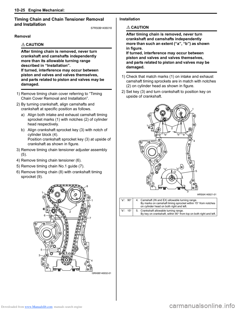
1) Remove timing chain cover referring to “Timing Chain Cover Removal and Installation”.
2) By turning crankshaft, align camshafts and crankshaft at specific position as follows.
a) Align both intake and exhaust camshaft timing sprocket marks (1) with notches (2) of cylinder
head respectively.
b) Align crankshaft sprocket key (3) with notch of cylinder block (4).
Position crankshaft sprocke t key (3) at upside of
crankshaft as shown in figure.
3) Remove timing chain tensioner adjuster assembly (5).
4) Remove timing chain tensioner (6).
5) Remove timing chain No.1 guide (7).
6) Remove timing chain (8) with crankshaft timing sprocket (9). Installation
CAUTION!
After timing chain is removed, never turn
crankshaft and camshafts independently
more than such an extent (“a”, “b”) as shown
in figure.
If turned, interferen
ce may occur between
piston and valves and valves themselves,
and parts related to piston and valves may be
damaged.
1) Check that match marks (1) on intake and exhaust camshaft timing sprockets are in match with notches
(2) on cylinder head as shown in figure.
2) Set key (3) and turn crankshaft to position key on upside of crankshaft.
3
4
1
1
2
5
67
8
9
I3RH0B140032-01
“a”: 90 °4. Camshaft (IN and EX) allowable turning range.
By marks on camshaft timing sprocket within 15 ° from notches
on cylinder head on both right and left.
“b”: 15 °5. Crankshaft allowable turning range.
By key on crankshaft, within 90 ° from top on both right and left.
“a”
“b”
“b”“b”
“b”
“a”
1
12
4
3
5
I4RS0A140021-01
Page 312 of 1496
Downloaded from www.Manualslib.com manuals search engine 1D-27 Engine Mechanical:
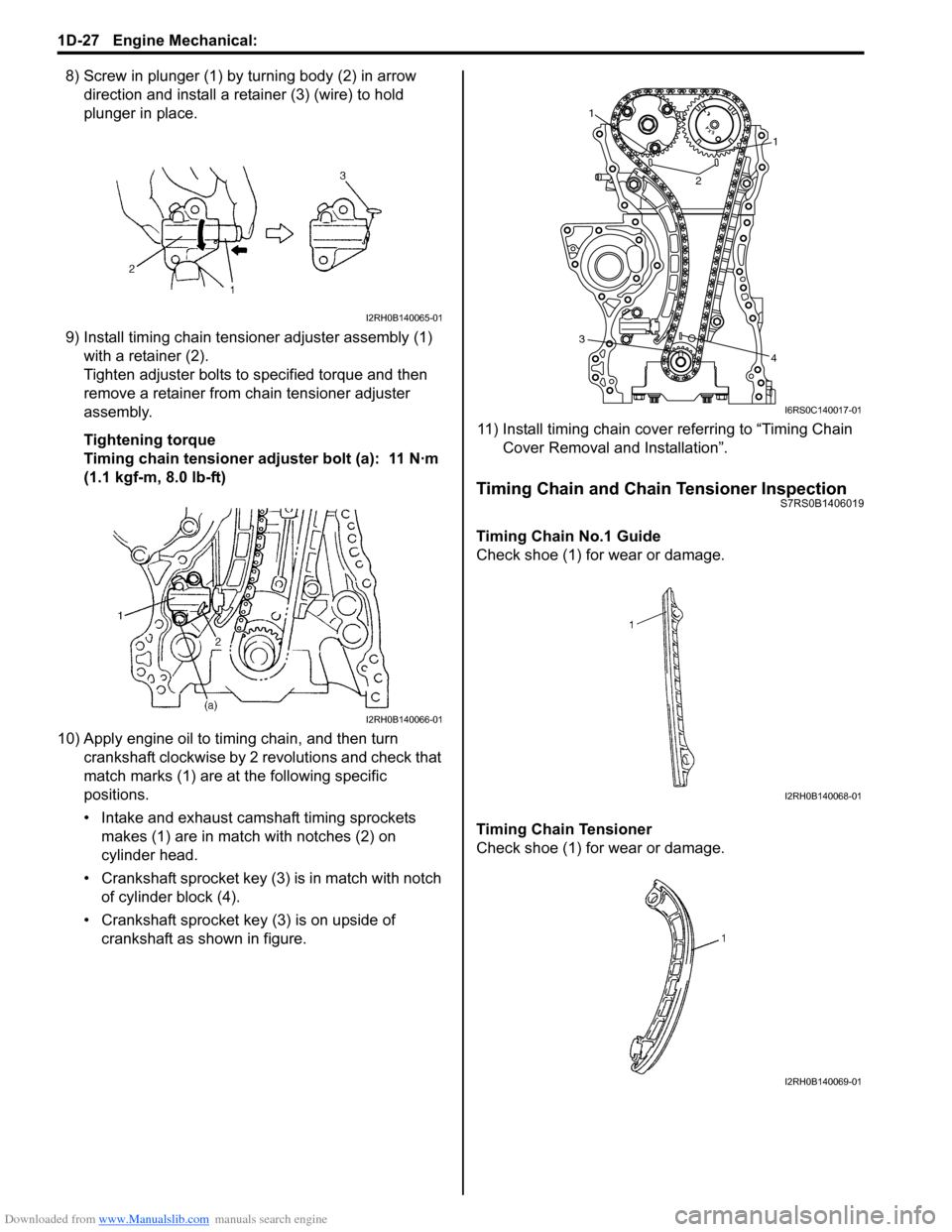
8) Screw in plunger (1) by turning body (2) in arrow direction and install a reta iner (3) (wire) to hold
plunger in place.
9) Install timing chain tensioner adjuster assembly (1) with a retainer (2).
Tighten adjuster bolts to specified torque and then
remove a retainer from chain tensioner adjuster
assembly.
Tightening torque
Timing chain tensioner adjuster bolt (a): 11 N·m
(1.1 kgf-m, 8.0 lb-ft)
10) Apply engine oil to timing chain, and then turn crankshaft clockwise by 2 revolutions and check that
match marks (1) are at the following specific
positions.
• Intake and exhaust camshaft timing sprockets makes (1) are in match with notches (2) on
cylinder head.
• Crankshaft sprocket key (3) is in match with notch of cylinder block (4).
• Crankshaft sprocket key (3) is on upside of crankshaft as shown in figure. 11) Install timing chain cover referring to “Timing Chain
Cover Removal and Installation”.
Timing Chain and Chain Tensioner InspectionS7RS0B1406019
Timing Chain No.1 Guide
Check shoe (1) for wear or damage.
Timing Chain Tensioner
Check shoe (1) for wear or damage.
I2RH0B140065-01
I2RH0B140066-01
1
1
2
3 4
I6RS0C140017-01
I2RH0B140068-01
I2RH0B140069-01
Page 315 of 1496
Downloaded from www.Manualslib.com manuals search engine Engine Mechanical: 1D-30
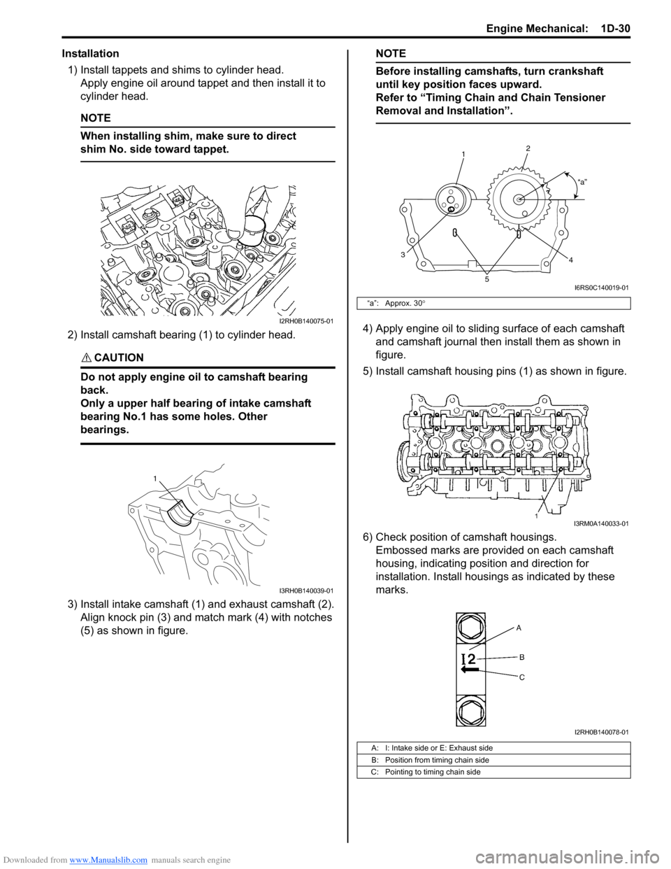
Installation1) Install tappets and shims to cylinder head. Apply engine oil around tappet and then install it to
cylinder head.
NOTE
When installing shim, make sure to direct
shim No. side toward tappet.
2) Install camshaft bearing (1) to cylinder head.
CAUTION!
Do not apply engine oil to camshaft bearing
back.
Only a upper half bearing of intake camshaft
bearing No.1 has some holes. Other
bearings.
3) Install intake camshaft (1) and exhaust camshaft (2). Align knock pin (3) and match mark (4) with notches
(5) as shown in figure.
NOTE
Before installing camshafts, turn crankshaft
until key position faces upward.
Refer to “Timing Chain and Chain Tensioner
Removal and Installation”.
4) Apply engine oil to sliding surface of each camshaft and camshaft journal then install them as shown in
figure.
5) Install camshaft housing pins (1) as shown in figure.
6) Check position of camshaft housings. Embossed marks are provided on each camshaft
housing, indicating position and direction for
installation. Install housings as indicated by these
marks.I2RH0B140075-01
1
I3RH0B140039-01
“a”: Approx. 30 °
A: I: Intake side or E: Exhaust side
B: Position from timing chain side
C: Pointing to timing chain side
1 2
3 4
5
“a”
I6RS0C140019-01
I3RM0A140033-01
I2RH0B140078-01
Page 349 of 1496
Downloaded from www.Manualslib.com manuals search engine Engine Mechanical: 1D-64
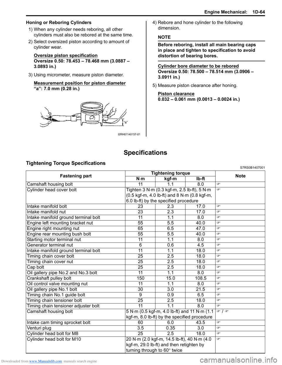
Honing or Reboring Cylinders1) When any cylinder needs reboring, all other cylinders must also be rebored at the same time.
2) Select oversized piston according to amount of cylinder wear.
Oversize piston specification
Oversize 0.50: 78.453 – 78.468 mm (3.0887 –
3.0893 in.)
3) Using micrometer, measure piston diameter. Measurement position for piston diameter
“a”: 7.0 mm (0.28 in.) 4) Rebore and hone cylinder to the following
dimension.
NOTE
Before reboring, install all main bearing caps
in place and tighten to specification to avoid
distortion of bearing bores.
Cylinder bore diameter to be rebored
Oversize 0.50: 78.500 – 78.514 mm (3.0906 –
3.0911 in.)
5) Measure piston clearance after honing. Piston clearance
0.032 – 0.061 mm (0.0013 – 0.0024 in.)
Specifications
Tightening Torque SpecificationsS7RS0B1407001
I2RH01140157-01
Fastening part Tightening torque
Note
N ⋅mkgf-mlb-ft
Camshaft housing bolt 11 1.1 8.0 �)
Cylinder head cover bolt Tighten 3 N ⋅m (0.3 kgf-m, 2.5 lb-ft), 5 N ⋅m
(0.5 kgf-m, 4.0 lb-ft) and 8 N ⋅m (0.8 kgf-m,
6.0 lb-ft) by the specified procedure �)
Intake manifold bolt 23 2.3 17.0 �)
Intake manifold nut 23 2.3 17.0 �)
Intake manifold ground terminal bolt 11 1.1 8.0 �)
Engine left mounting bracket nut 55 5.5 40.0 �)
Engine right mounting nut 65 6.5 47.0 �)
Engine rear mounting bush bolt 55 5.5 40.0 �)
Starting motor terminal nut 11 1.1 8.0 �)
Generator terminal nut 6 0.6 4.5 �)
Intake manifold ground terminal bolt 11 1.1 18.0 �)
Timing chain cover bolt 25 2.5 18.0 �)
Timing chain cover nut 25 2.5 18.0 �)
Cap bolt 25 2.5 18.0 �)
Oil gallery pipe No.2 and No.3 bolt 11 1.1 8.0 �)
Crankshaft pulley bolt 150 15.0 108.5 �)
Oil control valve mounting nut 11 1.1 8.0 �)
Oil gallery pipe No.1 bolt 30 3.0 21.5 �)
Timing chain No.1 guide bolt 9 0.9 6.5 �)
Timing chain tensioner bolt 25 2.5 18.0 �)
Timing chain tensioner adjuster bolt 11 1.1 8.0 �)
Camshaft housing bolt 5 N ⋅m (0.5 kgf-m, 4.0 lb-ft) and 11 N ⋅m (1.1
kgf-m, 8.0 lb-ft) by the specified procedure �)
/ �)
Intake cam timing sprocket bolt 60 6.0 43.5 �)
Venturi plug 3.5 0.35 3.0 �)
Cylinder head bolt for M8 25 2.5 18.0 �)
Cylinder head bolt for M10 20 N ⋅m (2.0 kgf-m, 14.5 lb-ft), 40 N ⋅m (4.0
kgf-m, 29.0 lb-ft) and then retighten by
turning through to 60 ° twice �)