Cylinder SUZUKI SWIFT 2007 2.G Service Owner's Manual
[x] Cancel search | Manufacturer: SUZUKI, Model Year: 2007, Model line: SWIFT, Model: SUZUKI SWIFT 2007 2.GPages: 1496, PDF Size: 34.44 MB
Page 162 of 1496
Downloaded from www.Manualslib.com manuals search engine 1A-112 Engine General Information and Diagnosis:
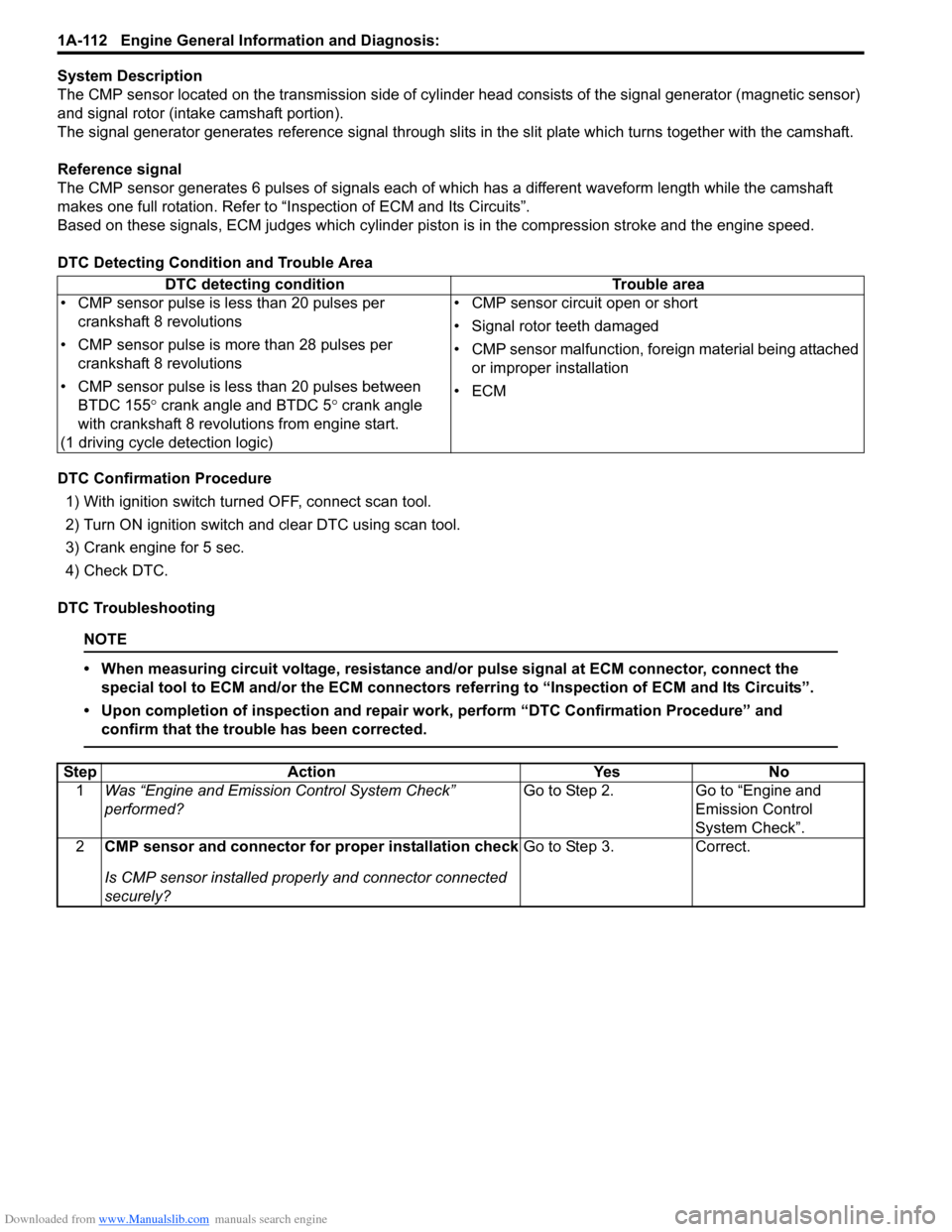
System Description
The CMP sensor located on the transmission side of cylinder head consists of the signal generator (magnetic sensor)
and signal rotor (intake camshaft portion).
The signal generator generates reference signal through slits in the slit plate which turns together with the camshaft.
Reference signal
The CMP sensor generates 6 pulses of si gnals each of which has a different waveform length while the camshaft
makes one full rotation. Refer to “Inspection of ECM and Its Circuits”.
Based on these signals, ECM judges which cylinder pist on is in the compression stroke and the engine speed.
DTC Detecting Condition and Trouble Area
DTC Confirmation Procedure 1) With ignition switch turned OFF, connect scan tool.
2) Turn ON ignition switch and clear DTC using scan tool.
3) Crank engine for 5 sec.
4) Check DTC.
DTC Troubleshooting
NOTE
• When measuring circuit voltage, resistance and/ or pulse signal at ECM connector, connect the
special tool to ECM and/or the ECM connectors re ferring to “Inspection of ECM and Its Circuits”.
• Upon completion of inspection and repair work, perform “DTC Confirmation Procedure” and confirm that the trouble has been corrected.
DTC detecting condition Trouble area
• CMP sensor pulse is less than 20 pulses per crankshaft 8 revolutions
• CMP sensor pulse is more than 28 pulses per crankshaft 8 revolutions
• CMP sensor pulse is less than 20 pulses between BTDC 155 ° crank angle and BTDC 5 ° crank angle
with crankshaft 8 revolutions from engine start.
(1 driving cycle detection logic) • CMP sensor circuit open or short
• Signal rotor teeth damaged
• CMP sensor malfunction, foreign material being attached
or improper installation
•ECM
Step Action YesNo
1 Was “Engine and Emission Control System Check”
performed? Go to Step 2.
Go to “Engine and
Emission Control
System Check”.
2 CMP sensor and connector for proper installation check
Is CMP sensor installed properly and connector connected
securely? Go to Step 3.
Correct.
Page 165 of 1496
Downloaded from www.Manualslib.com manuals search engine Engine General Information and Diagnosis: 1A-115
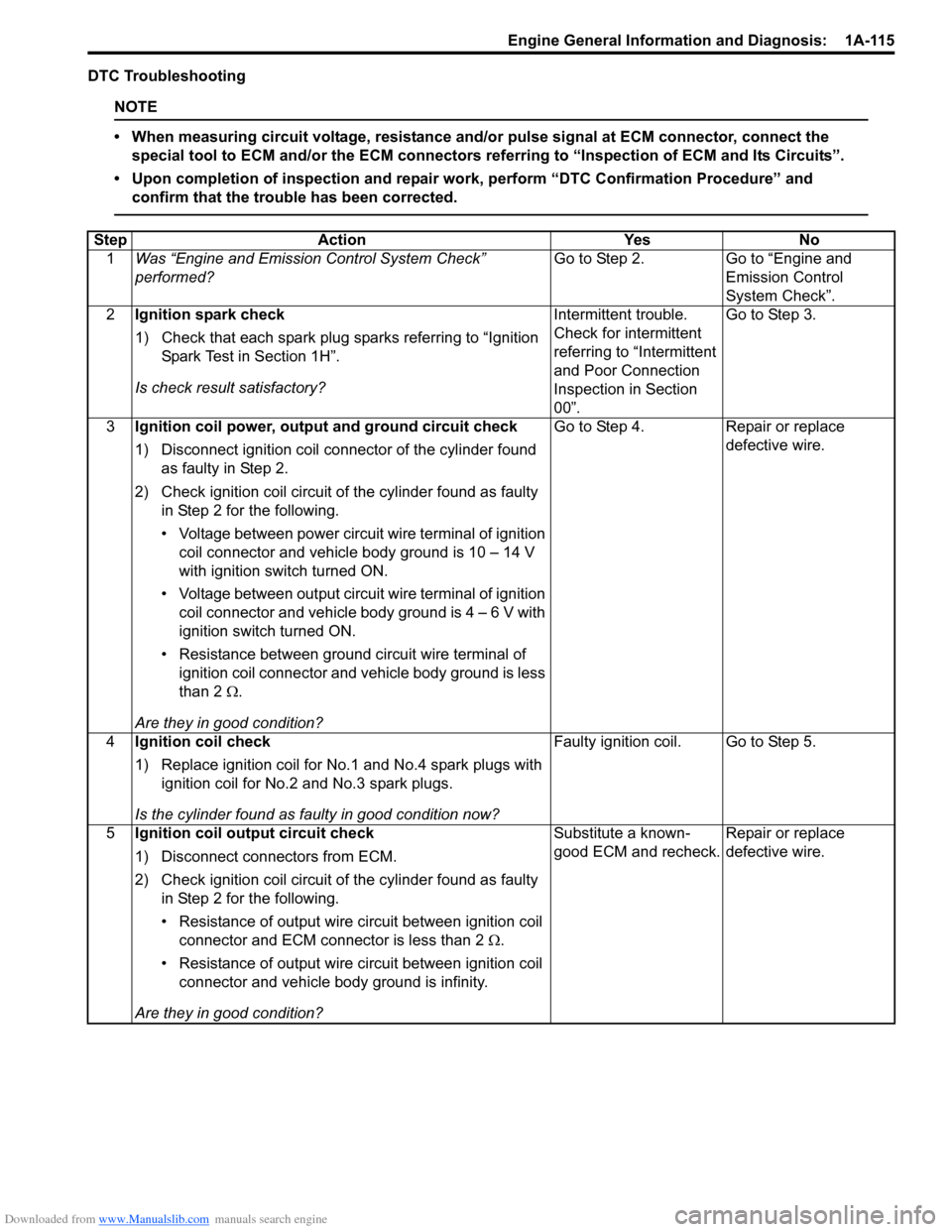
DTC Troubleshooting
NOTE
• When measuring circuit voltage, resistance and/or pulse signal at ECM connector, connect the
special tool to ECM and/or the ECM connectors re ferring to “Inspection of ECM and Its Circuits”.
• Upon completion of inspection and repair work, perform “DTC Confirmation Procedure” and confirm that the trouble has been corrected.
Step Action YesNo
1 Was “Engine and Emission Control System Check”
performed? Go to Step 2.
Go to “Engine and
Emission Control
System Check”.
2 Ignition spark check
1) Check that each spark plug sparks referring to “Ignition
Spark Test in Section 1H”.
Is check result satisfactory? Intermittent trouble.
Check for intermittent
referring to “Intermittent
and Poor Connection
Inspection in Section
00”.Go to Step 3.
3 Ignition coil power, output and ground circuit check
1) Disconnect ignition coil connector of the cylinder found
as faulty in Step 2.
2) Check ignition coil circuit of the cylinder found as faulty in Step 2 for the following.
• Voltage between power circuit wire terminal of ignition coil connector and vehicle body ground is 10 – 14 V
with ignition switch turned ON.
• Voltage between output circuit wire terminal of ignition coil connector and vehicle body ground is 4 – 6 V with
ignition switch turned ON.
• Resistance between ground circuit wire terminal of ignition coil connector and vehicle body ground is less
than 2 Ω.
Are they in good condition? Go to Step 4.
Repair or replace
defective wire.
4 Ignition coil check
1) Replace ignition coil for No.1 and No.4 spark plugs with
ignition coil for No.2 and No.3 spark plugs.
Is the cylinder found as faulty in good condition now? Faulty ignition coil. Go to Step 5.
5 Ignition coil output circuit check
1) Disconnect connectors from ECM.
2) Check ignition coil circuit of the cylinder found as faulty
in Step 2 for the following.
• Resistance of output wire circuit between ignition coil
connector and ECM connector is less than 2 Ω.
• Resistance of output wire circuit between ignition coil connector and vehicle b ody ground is infinity.
Are they in good condition? Substitute a known-
good ECM and recheck.
Repair or replace
defective wire.
Page 235 of 1496
Downloaded from www.Manualslib.com manuals search engine Engine General Information and Diagnosis: 1A-185
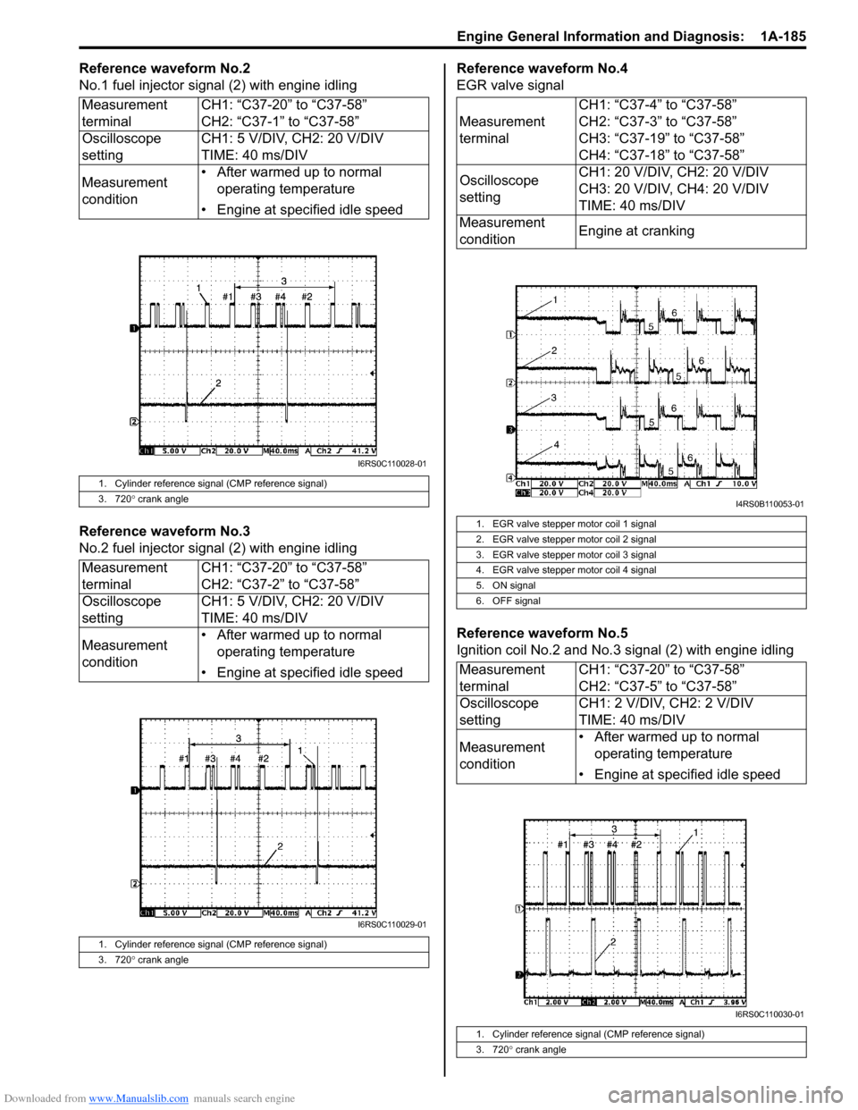
Reference waveform No.2
No.1 fuel injector signal (2) with engine idling
Reference waveform No.3
No.2 fuel injector sig nal (2) with engine idling Reference waveform No.4
EGR valve signal
Reference waveform No.5
Ignition coil No.2 and No.3 signal (2) with engine idling
Measurement
terminal
CH1: “C37-20” to “C37-58”
CH2: “C37-1” to “C37-58”
Oscilloscope
setting CH1: 5 V/DIV, CH2: 20 V/DIV
TIME: 40 ms/DIV
Measurement
condition • After warmed up to normal
operating temperature
• Engine at specified idle speed
1. Cylinder reference signal (CMP reference signal)
3. 720 ° crank angle
Measurement
terminal CH1: “C37-20” to “C37-58”
CH2: “C37-2” to “C37-58”
Oscilloscope
setting CH1: 5 V/DIV, CH2: 20 V/DIV
TIME: 40 ms/DIV
Measurement
condition • After warmed up to normal
operating temperature
• Engine at specified idle speed
1. Cylinder reference signal (CMP reference signal)
3. 720 ° crank angle
I6RS0C110028-01
I6RS0C110029-01
Measurement
terminal CH1: “C37-4” to “C37-58”
CH2: “C37-3” to “C37-58”
CH3: “C37-19” to “C37-58”
CH4: “C37-18” to “C37-58”
Oscilloscope
setting CH1: 20 V/DIV, CH2: 20 V/DIV
CH3: 20 V/DIV, CH4: 20 V/DIV
TIME: 40 ms/DIV
Measurement
condition Engine at cranking
1. EGR valve stepper motor coil 1 signal
2. EGR valve stepper motor coil 2 signal
3. EGR valve stepper motor coil 3 signal
4. EGR valve stepper motor coil 4 signal
5. ON signal
6. OFF signal
Measurement
terminalCH1: “C37-20” to “C37-58”
CH2: “C37-5” to “C37-58”
Oscilloscope
setting CH1: 2 V/DIV, CH2: 2 V/DIV
TIME: 40 ms/DIV
Measurement
condition • After warmed up to normal
operating temperature
• Engine at specified idle speed
1. Cylinder reference signal (CMP reference signal)
3. 720 ° crank angle
I4RS0B110053-01
I6RS0C110030-01
Page 236 of 1496
Downloaded from www.Manualslib.com manuals search engine 1A-186 Engine General Information and Diagnosis:
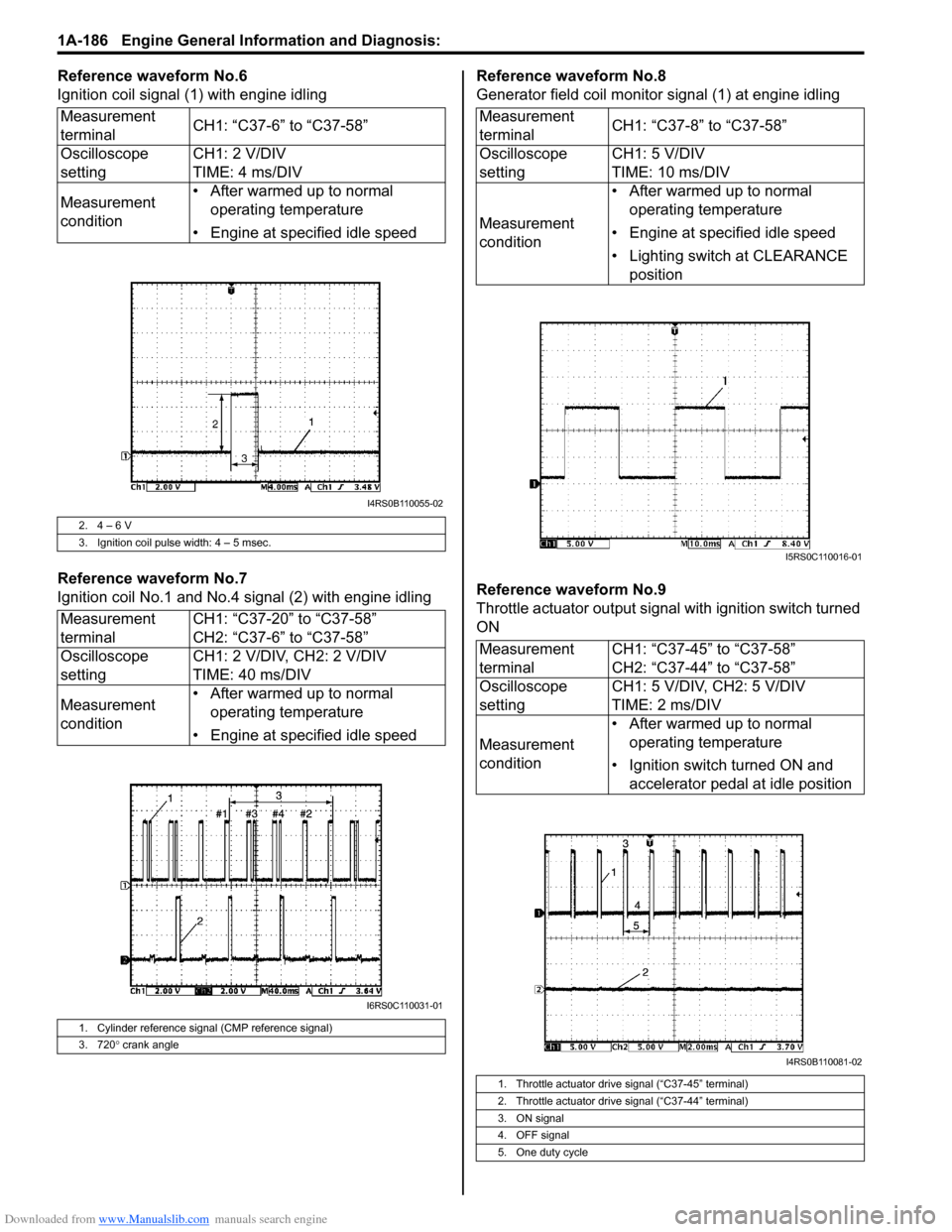
Reference waveform No.6
Ignition coil signal (1) with engine idling
Reference waveform No.7
Ignition coil No.1 and No.4 signal (2) with engine idlingReference waveform No.8
Generator field coil monitor signal (1) at engine idling
Reference waveform No.9
Throttle actuator output signal with ignition switch turned
ON
Measurement
terminal
CH1: “C37-6” to “C37-58”
Oscilloscope
setting CH1: 2 V/DIV
TIME: 4 ms/DIV
Measurement
condition • After warmed up to normal
operating temperature
• Engine at specified idle speed
2. 4 – 6 V
3. Ignition coil pulse width: 4 – 5 msec.
Measurement
terminal CH1: “C37-20” to “C37-58”
CH2: “C37-6” to “C37-58”
Oscilloscope
setting CH1: 2 V/DIV, CH2: 2 V/DIV
TIME: 40 ms/DIV
Measurement
condition • After warmed up to normal
operating temperature
• Engine at specified idle speed
1. Cylinder reference signal (CMP reference signal)
3. 720 ° crank angle
I4RS0B110055-02
I6RS0C110031-01
Measurement
terminal CH1: “C37-8” to “C37-58”
Oscilloscope
setting CH1: 5 V/DIV
TIME: 10 ms/DIV
Measurement
condition • After warmed up to normal
operating temperature
• Engine at specified idle speed
• Lighting switch at CLEARANCE position
Measurement
terminal CH1: “C37-45” to “C37-58”
CH2: “C37-44” to “C37-58”
Oscilloscope
setting CH1: 5 V/DIV, CH2: 5 V/DIV
TIME: 2 ms/DIV
Measurement
condition • After warmed up to normal
operating temperature
• Ignition switch turned ON and accelerator pedal at idle position
1. Throttle actuator drive signal (“C37-45” terminal)
2. Throttle actuator drive signal (“C37-44” terminal)
3. ON signal
4. OFF signal
5. One duty cycle
I5RS0C110016-01
I4RS0B110081-02
Page 238 of 1496
Downloaded from www.Manualslib.com manuals search engine 1A-188 Engine General Information and Diagnosis:
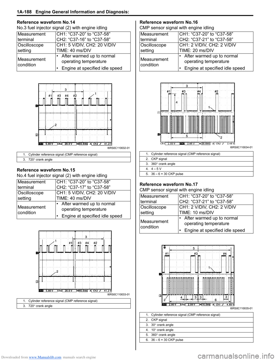
Reference waveform No.14
No.3 fuel injector signal (2) with engine idling
Reference waveform No.15
No.4 fuel injector sig nal (2) with engine idling Reference waveform No.16
CMP sensor signal with engine idling
Reference waveform No.17
CMP sensor signal with engine idling
Measurement
terminal
CH1: “C37-20” to “C37-58”
CH2: “C37-16” to “C37-58”
Oscilloscope
setting CH1: 5 V/DIV, CH2: 20 V/DIV
TIME: 40 ms/DIV
Measurement
condition • After warmed up to normal
operating temperature
• Engine at specified idle speed
1. Cylinder reference signal (CMP reference signal)
3. 720 ° crank angle
Measurement
terminal CH1: “C37-20” to “C37-58”
CH2: “C37-17” to “C37-58”
Oscilloscope
setting CH1: 5 V/DIV, CH2: 20 V/DIV
TIME: 40 ms/DIV
Measurement
condition • After warmed up to normal
operating temperature
• Engine at specified idle speed
1. Cylinder reference signal (CMP reference signal)
3. 720 ° crank angle
I6RS0C110032-01
I6RS0C110033-01
Measurement
terminal CH1: “C37-20” to “C37-58”
CH2: “C37-21” to “C37-58”
Oscilloscope
setting CH1: 2 V/DIV, CH2: 2 V/DIV
TIME: 20 ms/DIV
Measurement
condition • After warmed up to normal
operating temperature
• Engine at specified idle speed
1. Cylinder reference signal (CMP reference signal)
2. CKP signal
3. 360 ° crank angle
4. 4 – 5 V
5. 36 – 6 = 30 CKP pulse
Measurement
terminal CH1: “C37-20” to “C37-58”
CH2: “C37-21” to “C37-58”
Oscilloscope
setting CH1: 2 V/DIV, CH2: 2 V/DIV
TIME: 10 ms/DIV
Measurement
condition • After warmed up to normal
operating temperature
• Engine at specified idle speed
1. Cylinder reference signal (CMP reference signal)
2. CKP signal
3. 30 ° crank angle
4. 10 ° crank angle
5. 360 ° crank angle
6. 36 – 6 = 30 CKP pulse
I6RS0C110034-01
I6RS0C110035-01
Page 240 of 1496
Downloaded from www.Manualslib.com manuals search engine 1A-190 Engine General Information and Diagnosis:
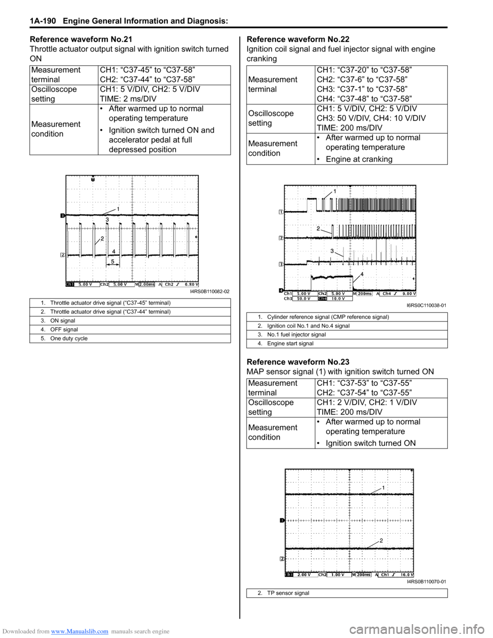
Reference waveform No.21
Throttle actuator output signal with ignition switch turned
ONReference waveform No.22
Ignition coil signal and fuel injector signal with engine
cranking
Reference waveform No.23
MAP sensor signal (1) with ignition switch turned ON
Measurement
terminal
CH1: “C37-45” to “C37-58”
CH2: “C37-44” to “C37-58”
Oscilloscope
setting CH1: 5 V/DIV, CH2: 5 V/DIV
TIME: 2 ms/DIV
Measurement
condition • After warmed up to normal
operating temperature
• Ignition switch turned ON and accelerator pedal at full
depressed position
1. Throttle actuator drive signal (“C37-45” terminal)
2. Throttle actuator drive signal (“C37-44” terminal)
3. ON signal
4. OFF signal
5. One duty cycle
I4RS0B110082-02
Measurement
terminal CH1: “C37-20” to “C37-58”
CH2: “C37-6” to “C37-58”
CH3: “C37-1” to “C37-58”
CH4: “C37-48” to “C37-58”
Oscilloscope
setting CH1: 5 V/DIV, CH2: 5 V/DIV
CH3: 50 V/DIV, CH4: 10 V/DIV
TIME: 200 ms/DIV
Measurement
condition • After warmed up to normal
operating temperature
• Engine at cranking
1. Cylinder reference signal (CMP reference signal)
2. Ignition coil No.1 and No.4 signal
3. No.1 fuel injector signal
4. Engine start signal
Measurement
terminal CH1: “C37-53” to “C37-55”
CH2: “C37-54” to “C37-55”
Oscilloscope
setting CH1: 2 V/DIV, CH2: 1 V/DIV
TIME: 200 ms/DIV
Measurement
condition • After warmed up to normal
operating temperature
• Ignition switch turned ON
2. TP sensor signal
I6RS0C110038-01
I4RS0B110070-01
Page 242 of 1496
Downloaded from www.Manualslib.com manuals search engine 1A-192 Engine General Information and Diagnosis:
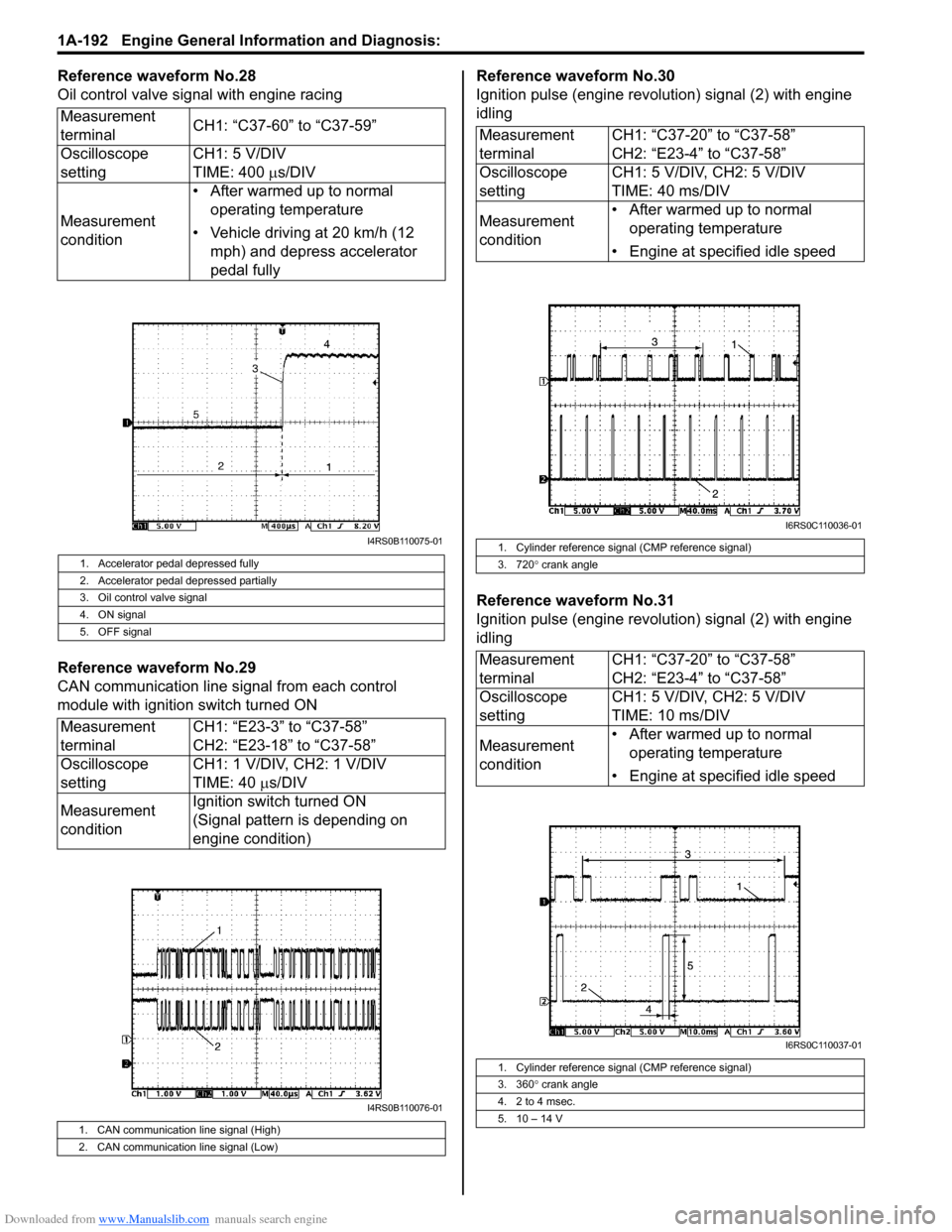
Reference waveform No.28
Oil control valve signal with engine racing
Reference waveform No.29
CAN communication line signal from each control
module with ignition switch turned ONReference waveform No.30
Ignition pulse (engine revolution) signal (2) with engine
idling
Reference waveform No.31
Ignition pulse (engine revolution) signal (2) with engine
idling
Measurement
terminal
CH1: “C37-60” to “C37-59”
Oscilloscope
setting CH1: 5 V/DIV
TIME: 400
µs/DIV
Measurement
condition • After warmed up to normal
operating temperature
• Vehicle driving at 20 km/h (12 mph) and depress accelerator
pedal fully
1. Accelerator pedal depressed fully
2. Accelerator pedal depressed partially
3. Oil control valve signal
4. ON signal
5. OFF signal
Measurement
terminal CH1: “E23-3” to “C37-58”
CH2: “E23-18” to “C37-58”
Oscilloscope
setting CH1: 1 V/DIV, CH2: 1 V/DIV
TIME: 40
µs/DIV
Measurement
condition Ignition switch turned ON
(Signal pattern is depending on
engine condition)
1. CAN communication line signal (High)
2. CAN communication line signal (Low)
I4RS0B110075-01
I4RS0B110076-01
Measurement
terminal
CH1: “C37-20” to “C37-58”
CH2: “E23-4” to “C37-58”
Oscilloscope
setting CH1: 5 V/DIV, CH2: 5 V/DIV
TIME: 40 ms/DIV
Measurement
condition • After warmed up to normal
operating temperature
• Engine at specified idle speed
1. Cylinder reference signal (CMP reference signal)
3. 720 ° crank angle
Measurement
terminal CH1: “C37-20” to “C37-58”
CH2: “E23-4” to “C37-58”
Oscilloscope
setting CH1: 5 V/DIV, CH2: 5 V/DIV
TIME: 10 ms/DIV
Measurement
condition • After warmed up to normal
operating temperature
• Engine at specified idle speed
1. Cylinder reference signal (CMP reference signal)
3. 360 ° crank angle
4. 2 to 4 msec.
5. 10 – 14 V
I6RS0C110036-01
I6RS0C110037-01
Page 271 of 1496
Downloaded from www.Manualslib.com manuals search engine Aux. Emission Control Devices: 1B-4
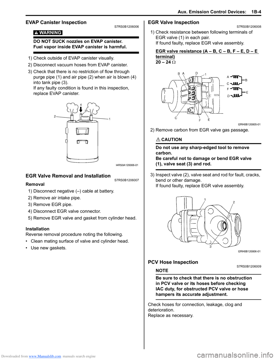
EVAP Canister InspectionS7RS0B1206006
WARNING!
DO NOT SUCK nozzles on EVAP canister.
Fuel vapor inside EVAP canister is harmful.
1) Check outside of EVAP canister visually.
2) Disconnect vacuum hoses from EVAP canister.
3) Check that there is no restriction of flow through purge pipe (1) and air pipe (2) when air is blown (4)
into tank pipe (3).
If any faulty condition is found in this inspection,
replace EVAP canister.
EGR Valve Removal and InstallationS7RS0B1206007
Removal
1) Disconnect negative (–) cable at battery.
2) Remove air intake pipe.
3) Remove EGR pipe.
4) Disconnect EGR valve connector.
5) Remove EGR valve and gasket from cylinder head.
Installation
Reverse removal procedure noting the following.
• Clean mating surface of valve and cylinder head.
• Use new gaskets.
EGR Valve InspectionS7RS0B1206008
1) Check resistance between following terminals of EGR valve (1) in each pair.
If found faulty, replace EGR valve assembly.
EGR valve resistance (A – B, C – B, F – E, D – E
terminal)
20 – 24 Ω
2) Remove carbon from EGR valve gas passage.
CAUTION!
Do not use any sharp-edged tool to remove
carbon.
Be careful not to damage or bend EGR valve
(1), valve seat (3) and rod.
3) Inspect valve (2), valve seat and rod for fault, cracks, bend or other damage.
If found faulty, replace EGR valve assembly.
PCV Hose InspectionS7RS0B1206009
NOTE
Be sure to check that there is no obstruction
in PCV valve or its hoses before checking
IAC duty, for obstructed PCV valve or hose
hampers its accurate adjustment.
Check hoses for connection, leakage, clog and
deterioration.
Replace as necessary.
I4RS0A120006-01
I2RH0B120005-01
I2RH0B120006-01
Page 272 of 1496
Downloaded from www.Manualslib.com manuals search engine 1B-5 Aux. Emission Control Devices:
PCV Valve InspectionS7RS0B1206010
NOTE
Be sure to check that there is no obstruction
in PCV valve or its hoses before checking
IAC duty, for obstructed PCV valve or hose
hampers its accurate adjustment.
1) Detach air cleaner assembly.
2) Disconnect PCV valve from cylinder head cover and install plug to head cover hole.
3) Install air cleaner assembly temporarily.
4) Run engine at idle.
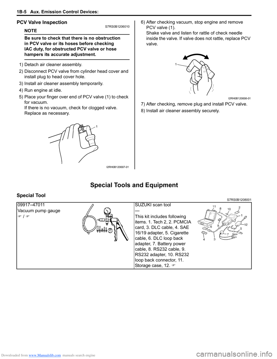
5) Place your finger over end of PCV valve (1) to check for vacuum.
If there is no vacuum, ch eck for clogged valve.
Replace as necessary. 6) After checking vacuum, stop engine and remove
PCV valve (1).
Shake valve and listen for rattle of check needle
inside the valve. If valve does not rattle, replace PCV
valve.
7) After checking, remove plug and install PCV valve.
8) Install air cleaner assembly securely.
Special Tools and Equipment
Special ToolS7RS0B1208001
I2RH0B120007-01
I2RH0B120008-01
09917–47011 SUZUKI scan tool
Vacuum pump gauge —
�) / �) This kit includes following
items. 1. Tech 2, 2. PCMCIA
card, 3. DLC cable, 4. SAE
16/19 adapter, 5. Cigarette
cable, 6. DLC loop back
adapter, 7. Battery power
cable, 8. RS232 cable, 9.
RS232 adapter, 10. RS232
loop back connector, 11.
Storage case, 12. �)
Page 280 of 1496
Downloaded from www.Manualslib.com manuals search engine 1C-8 Engine Electrical Devices:
Installation
Reverse removal procedure noting the following.
• Tighten heated oxygen sensor to specified torque.Tightening torque
Heated oxygen sensor (a): 45 N·m (4.5 kgf-m,
32.5 lb-ft)
• Install exhaust manifold referring to “Exhaust Manifold Removal and Installation in Section 1K”, if removed.
• Connect connector of heated oxygen sensor and clamp wire harness securely.
• After installing heated oxygen sensor, start engine and check that no exhaust gas leakage exists.
CMP Sensor Removal and InstallationS7RS0B1306012
Removal
1) Disconnect negative (–) cable at battery.
2) Disconnect connector from CMP sensor.
3) Remove CMP sensor from cylinder head.
Installation 1) Install CMP sensor to cylinder head.
Tightening torque
CMP sensor bolt (a): 10 N·m (1.0 kgf-m, 7.5 lb-ft)
2) Connect connector to CMP sensor securely.
3) Connect negative (–) cable to battery.
Camshaft Position (CMP) Sensor InspectionS7RS0B1306013
Visual check
• Check that O-ring is free from damage.
• Check that end face of sensor and signal rotor tooth are free from any metal particles and damage.
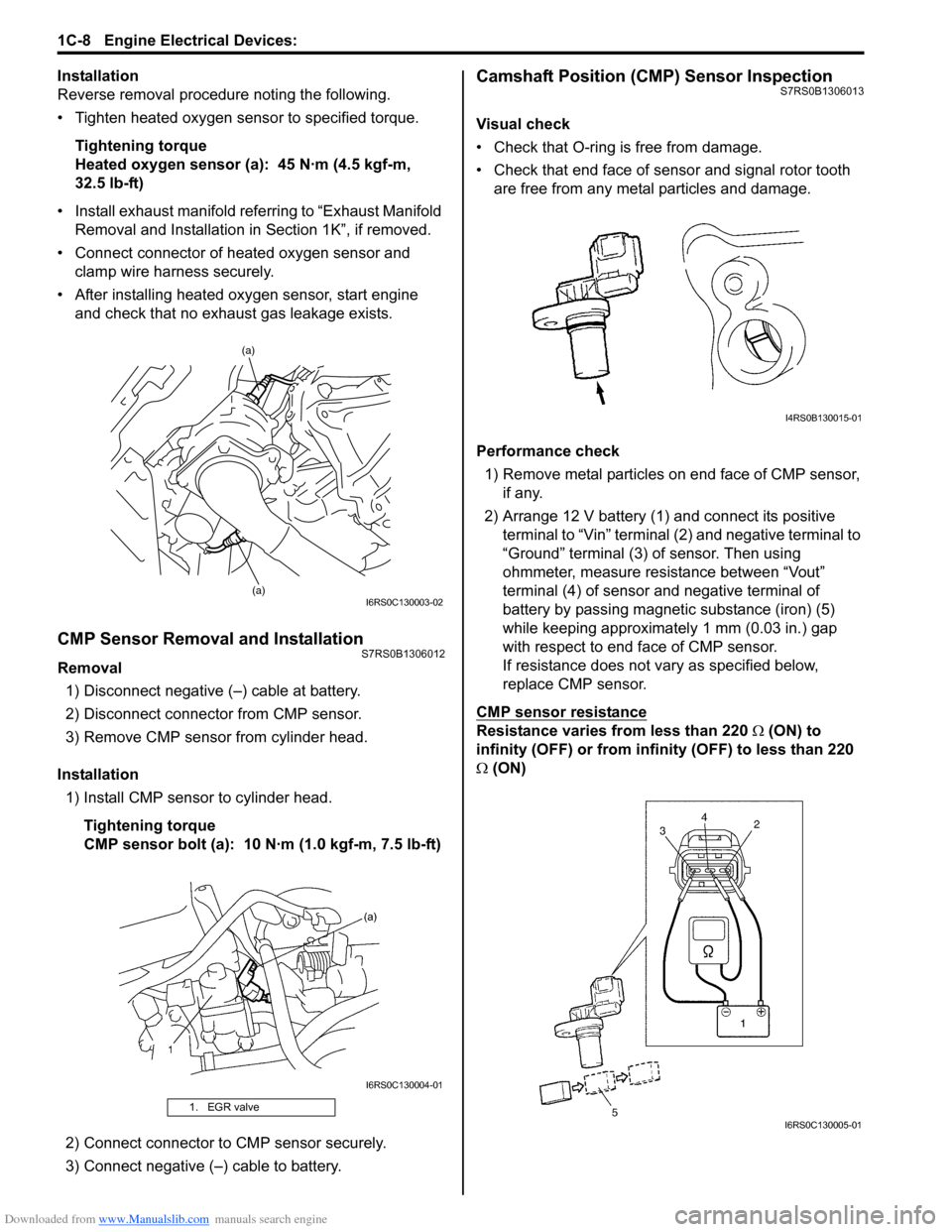
Performance check 1) Remove metal particles on end face of CMP sensor, if any.
2) Arrange 12 V battery (1) and connect its positive terminal to “Vin” terminal (2) and negative terminal to
“Ground” terminal (3) of sensor. Then using
ohmmeter, measure resistance between “Vout”
terminal (4) of sensor and negative terminal of
battery by passing magnetic substance (iron) (5)
while keeping approximately 1 mm (0.03 in.) gap
with respect to end face of CMP sensor.
If resistance does not vary as specified below,
replace CMP sensor.
CMP sensor resistance
Resistance varies from less than 220 Ω (ON) to
infinity (OFF) or from infinity (OFF) to less than 220
Ω (ON)
1. EGR valve
(a)
(a)
I6RS0C130003-02
I6RS0C130004-01
I4RS0B130015-01
I6RS0C130005-01