Gear shift light SUZUKI SWIFT 2007 2.G Service Owner's Manual
[x] Cancel search | Manufacturer: SUZUKI, Model Year: 2007, Model line: SWIFT, Model: SUZUKI SWIFT 2007 2.GPages: 1496, PDF Size: 34.44 MB
Page 849 of 1496

Downloaded from www.Manualslib.com manuals search engine Manual Transmission/Transaxle: 5B-35
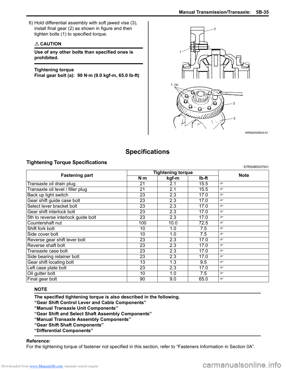
6) Hold differential assembly with soft jawed vise (3),
install final gear (2) as shown in figure and then
tighten bolts (1) to specified torque.
CAUTION!
Use of any other bolts than specified ones is
prohibited.
Tightening torque
Final gear bolt (a): 90 N·m (9.0 kgf-m, 65.0 lb-ft)
Specifications
Tightening Torque SpecificationsS7RS0B5207001
NOTE
The specified tightening torque is also described in the following.
“Gear Shift Control Leve r and Cable Components”
“Manual Transaxle Unit Components”
“Gear Shift and Select Shaft Assembly Components”
“Manual Transaxle Assembly Components”
“Gear Shift Shaft Components”
“Differential Components”
Reference:
For the tightening torque of fastener not specified in this section, refer to “Fasteners Information in Section 0A”.
I4RS0A520043-01
Fastening part Tightening torque
Note
N ⋅mkgf-mlb-ft
Transaxle oil drain plug 21 2.1 15.5 �)
Transaxle oil level / filler plug 21 2.1 15.5 �)
Back up light switch 23 2.3 17.0 �)
Gear shift guide case bolt 23 2.3 17.0 �)
Select lever bracket bolt 23 2.3 17.0 �)
Gear shift interlock bolt 23 2.3 17.0 �)
5th to reverse interlock guide bolt 23 2.3 17.0 �)
Countershaft nut 100 10.0 72.5 �)
Shift fork bolt 10 1.0 7.5 �)
Side cover bolt 10 1.0 7.5 �)
Reverse gear shift lever bolt 23 2.3 17.0 �)
Reverse shaft bolt 23 2.3 17.0 �)
Transaxle case bolt 23 2.3 17.0 �)
Side bearing retainer bolt 23 2.3 17.0 �)
Gear shift locating bolt 13 1.3 9.5 �)
Left case plate bolt 23 2.3 17.0 �)
Oil gutter bolt 10 1.0 7.5 �)
Final gear bolt 90 9.0 65.0 �)
Page 855 of 1496

Downloaded from www.Manualslib.com manuals search engine Clutch: 5C-3
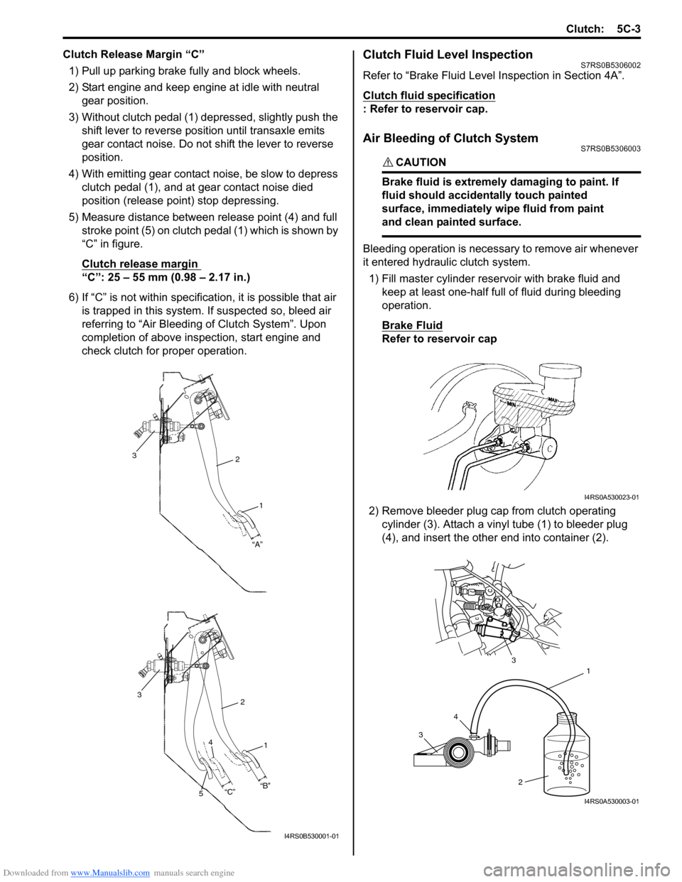
Clutch Release Margin “C”1) Pull up parking brake fully and block wheels.
2) Start engine and keep engine at idle with neutral gear position.
3) Without clutch pedal (1) dep ressed, slightly push the
shift lever to re verse position until transaxle emits
gear contact noise. Do not shift the lever to reverse
position.
4) With emitting gear contact noise, be slow to depress clutch pedal (1), and at gear contact noise died
position (release point) stop depressing.
5) Measure distance between release point (4) and full stroke point (5) on clutch pedal (1) which is shown by
“C” in figure.
Clutch release margin
“C”: 25 – 55 mm (0.98 – 2.17 in.)
6) If “C” is not within specificat ion, it is possible that air
is trapped in this system. If suspected so, bleed air
referring to “Air Bleeding of Clutch System”. Upon
completion of above inspection, start engine and
check clutch for proper operation.
Clutch Fluid Level InspectionS7RS0B5306002
Refer to “Brake Fluid Level Inspection in Section 4A”.
Clutch fluid specification
: Refer to reservoir cap.
Air Bleeding of Clutch SystemS7RS0B5306003
CAUTION!
Brake fluid is extremely damaging to paint. If
fluid should accidentally touch painted
surface, immediately wipe fluid from paint
and clean painted surface.
Bleeding operation is necessary to remove air whenever
it entered hydraulic clutch system.
1) Fill master cylinder reservoir with brake fluid and keep at least one-half full of fluid during bleeding
operation.
Brake Fluid
Refer to reservoir cap
2) Remove bleeder plug cap from clutch operating cylinder (3). Attach a vinyl tube (1) to bleeder plug
(4), and insert the other end into container (2).
2
1
“A”
3
2
1
3
“B”
“C”
4
5
I4RS0B530001-01
I4RS0A530023-01
3 4 1
2
3
I4RS0A530003-01