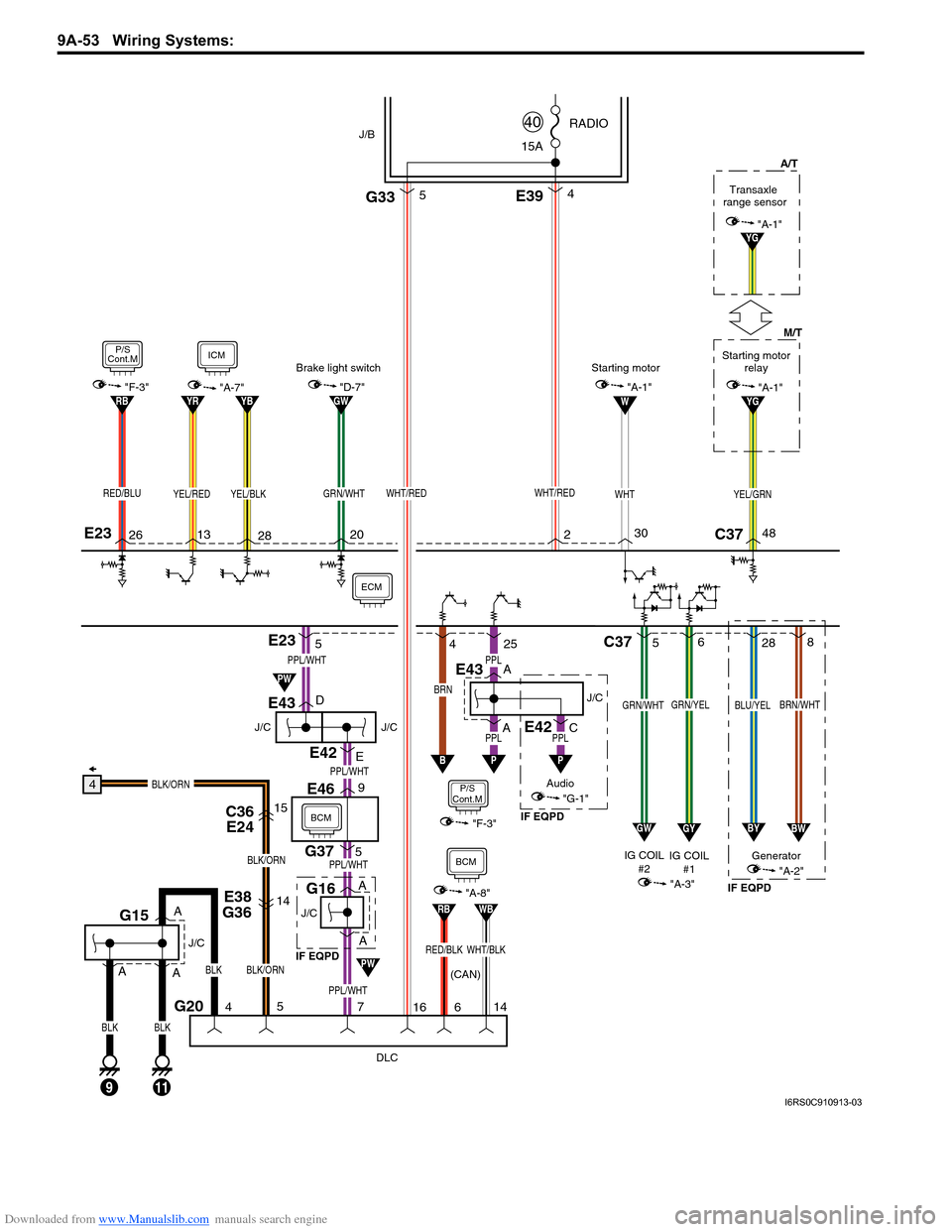
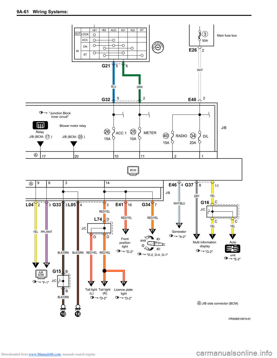
Generator 1 wiring SUZUKI SWIFT 2007 2.G Service Owner's Manual
[x] Cancel search | Manufacturer: SUZUKI, Model Year: 2007, Model line: SWIFT, Model: SUZUKI SWIFT 2007 2.GPages: 1496, PDF Size: 34.44 MB
Page 1224 of 1496

Downloaded from www.Manualslib.com manuals search engine 9A-53 Wiring Systems:
J/C
E43
J/C
G16
DLC
G20
G375
E469
E38
G3614
C36 E2415
BLK/ORN
BLK/ORN
BLK/ORN
4
BLK
11
J/C
G15
5
4
516
WHT/RED
C37
GRN/YELGRN/WHT
5 6
YG
BRN
B
P/S
Cont.M
4
"F-3"
25
A
A D
E
AA
PPL/WHT
PPL/WHT
PPL/WHT
PPL/WHT
YEL/GRNWHT/RED
BLK
9
A
PPL
E42
PPLJ/C
ECM
E394
J/B15A RADIO
40
E23
E23
YEL/BLKYEL/REDRED/BLU
13
282620
BLK
2C37
M/T
A/T
48
W
WHT
30
GYGW
BRN/WHTBLU/YEL
28
8
BWBY
IG COIL
#1 Generator
IG COIL
#2
(CAN) "A-3""A-2"
Audio
"G-1"
GRN/WHT
P
7
BCM
Starting motor relay
"A-1"
Transaxle
range sensor
YG"A-1"
ICM
"A-7"
P/S
Cont.M
"F-3"YBYRRBGW"D-7"
Brake light switch
"A-1"Starting motor
PW
PW
G335
WHT/BLKRED/BLK
RBWB
"A-8"
14
6
BCM
A
J/C
E43
APPL
P
E42C
IF EQPD IF EQPD
IF EQPD
I6RS0C910913-03
Page 1232 of 1496

Downloaded from www.Manualslib.com manuals search engine 9A-61 Wiring Systems:
50A
3
J/B
15ARADIO
40
2
15A
ACC 1
26
10
1
20AD/L
34
11
10A
METER
25
Main fuse box
WHT
E402
20
Blower motor relay
"Junction Block Inner circuit"
Relay
J/B (BCM- 20 )J/B (BCM- 17 )
17
2L04
9
3
83
B BG33
3
4L05
10
J/C
G15
BLK/ORN
BLK/ORN
16
BLK/ORN
"F-1"
YELPPL/WHT
A/B
SDM
14
316E417G34
Front
position light
"D-2"
"D-2, D-4, G-1"
J/B
RED/YELRED/YEL
J/C
L74D
DD
Licence plate light
"D-2"
YPW
"A-2"
Generator
E464
WHT/BLU
WB
RYRY
RYRYRY
Tail light
(R)
Tail light
(L)
"D-2"
RED/YEL
RED/YEL
RED/YEL
811
C CG37
J/C
G16
YEL
GRYYEL
GY
C
YEL
Y
"G-2"
Multi information
display Auto
unit
"E-2"
A
A
J/C
2E26
+B1
LOCK
ACC
ON
ST ACC IG1 IG2
STOUT
IN
+B2
BLUGRN
G3252
56G21
J/B side connector (BCM)
A
BCM
I7RS0B910919-01
Page 1284 of 1496

Downloaded from www.Manualslib.com manuals search engine 9B-2 Lighting Systems:
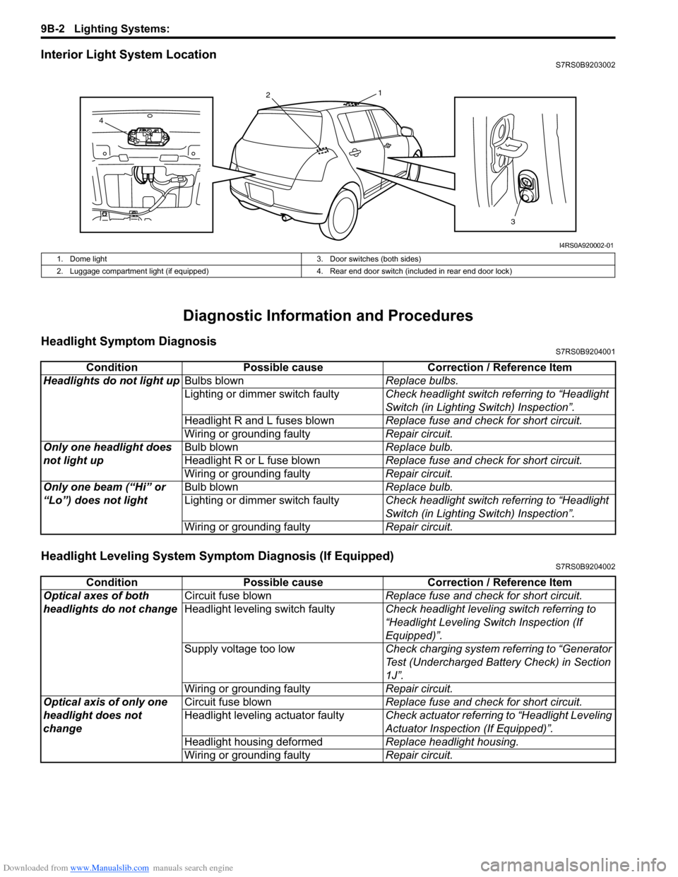
Interior Light System LocationS7RS0B9203002
Diagnostic Information and Procedures
Headlight Symptom DiagnosisS7RS0B9204001
Headlight Leveling System Symptom Diagnosis (If Equipped)S7RS0B9204002
13
2
4
I4RS0A920002-01
1. Dome light 3. Door switches (both sides)
2. Luggage compartment light (if equipped) 4. Rear end door switch (included in rear end door lock)
ConditionPossible cause Correction / Reference Item
Headlights do not light up Bulbs blown Replace bulbs.
Lighting or dimmer switch faulty Check headlight switch referring to “Headlight
Switch (in Lighting Switch) Inspection”.
Headlight R and L fuses blown Replace fuse and check for short circuit.
Wiring or grounding faulty Repair circuit.
Only one headlight does
not light up Bulb blown
Replace bulb.
Headlight R or L fuse blown Replace fuse and check for short circuit.
Wiring or grounding faulty Repair circuit.
Only one beam (“Hi” or
“Lo”) does not light Bulb blown
Replace bulb.
Lighting or dimmer switch faulty Check headlight switch referring to “Headlight
Switch (in Lighting Switch) Inspection”.
Wiring or grounding faulty Repair circuit.
ConditionPossible cause Correction / Reference Item
Optical axes of both
headlights do not change Circuit fuse blown
Replace fuse and check for short circuit.
Headlight leveling switch faulty Check headlight leveling switch referring to
“Headlight Leveling Switch Inspection (If
Equipped)”.
Supply voltage too low Check charging system referring to “Generator
Test (Undercharged Battery Check) in Section
1J”.
Wiring or grounding faulty Repair circuit.
Optical axis of only one
headlight does not
change Circuit fuse blown
Replace fuse and check for short circuit.
Headlight leveling actuator faulty Check actuator referring to “Headlight Leveling
Actuator Inspection (If Equipped)”.
Headlight housing deformed Replace headlight housing.
Wiring or grounding faulty Repair circuit.
Page 1420 of 1496

Downloaded from www.Manualslib.com manuals search engine 10B-17 Body Electrical Control System:
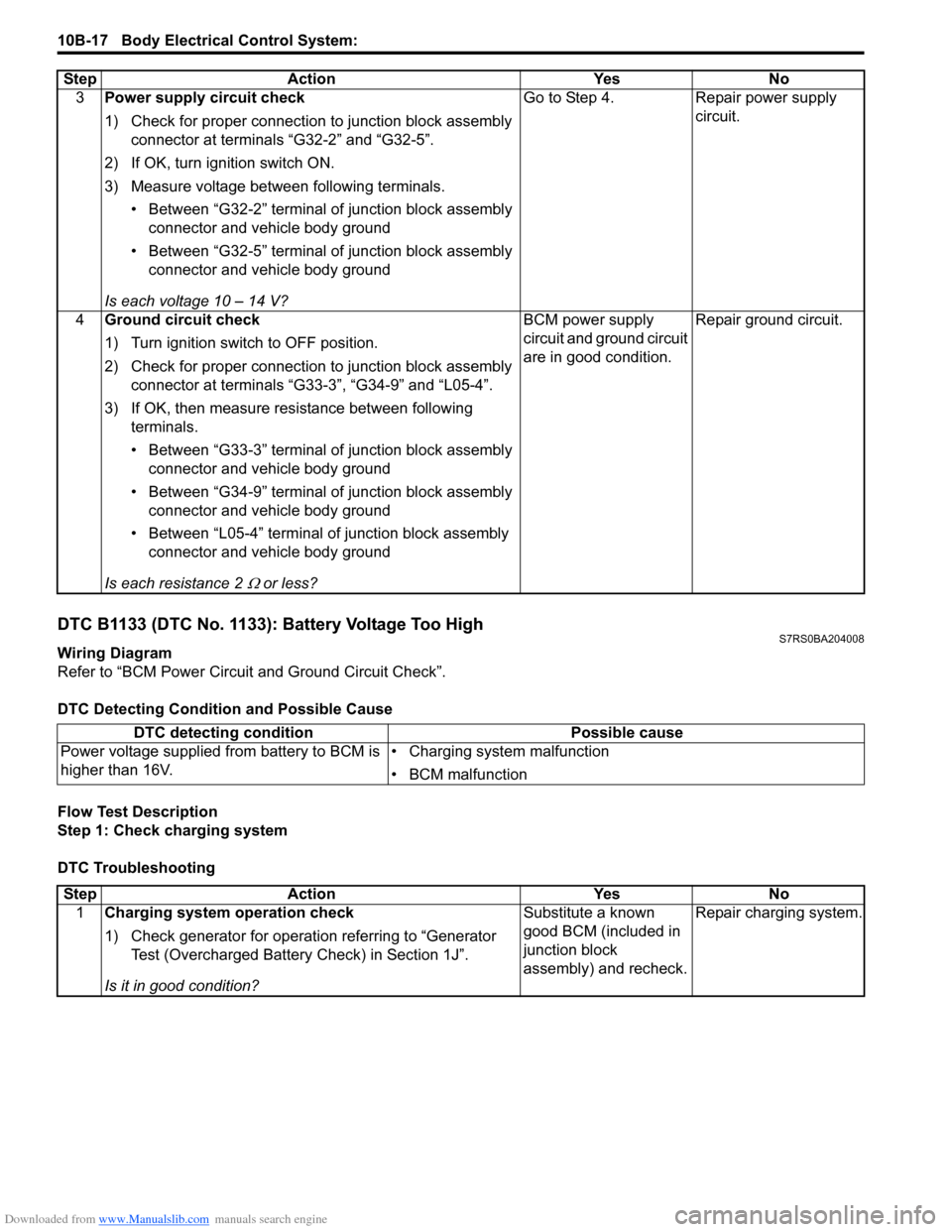
DTC B1133 (DTC No. 1133): Battery Voltage Too HighS7RS0BA204008
Wiring Diagram
Refer to “BCM Power Circuit and Ground Circuit Check”.
DTC Detecting Conditi on and Possible Cause
Flow Test Description
Step 1: Check charging system
DTC Troubleshooting 3
Power supply circuit check
1) Check for proper connection to junction block assembly
connector at terminals “G32-2” and “G32-5”.
2) If OK, turn ignition switch ON.
3) Measure voltage between following terminals. • Between “G32-2” terminal of junction block assembly connector and vehicle body ground
• Between “G32-5” terminal of junction block assembly connector and vehicle body ground
Is each voltage 10 – 14 V? Go to Step 4. Repair power supply
circuit.
4 Ground circuit check
1) Turn ignition switch to OFF position.
2) Check for proper connection to junction block assembly
connector at terminals “G33-3”, “G34-9” and “L05-4”.
3) If OK, then measure resistance between following terminals.
• Between “G33-3” terminal of junction block assembly connector and vehicle body ground
• Between “G34-9” terminal of junction block assembly connector and vehicle body ground
• Between “L05-4” terminal of junction block assembly connector and vehicle body ground
Is each resistance 2
Ω or less? BCM power supply
circuit and ground circuit
are in good condition.
Repair ground circuit.
Step Action Yes No
DTC detecting condition
Possible cause
Power voltage supplied from battery to BCM is
higher than 16V. • Charging system malfunction
• BCM malfunction
Step
Action YesNo
1 Charging system operation check
1) Check generator for operation referring to “Generator
Test (Overcharged Battery Check) in Section 1J”.
Is it in good condition? Substitute a known
good BCM (included in
junction block
assembly) and recheck.
Repair charging system.