Head bolts SUZUKI SWIFT 2007 2.G Service Owner's Manual
[x] Cancel search | Manufacturer: SUZUKI, Model Year: 2007, Model line: SWIFT, Model: SUZUKI SWIFT 2007 2.GPages: 1496, PDF Size: 34.44 MB
Page 750 of 1496
Downloaded from www.Manualslib.com manuals search engine 5A-106 Automatic Transmission/Transaxle:
Automatic Transaxle Unit Dismounting and
Remounting
S7RS0B5106031
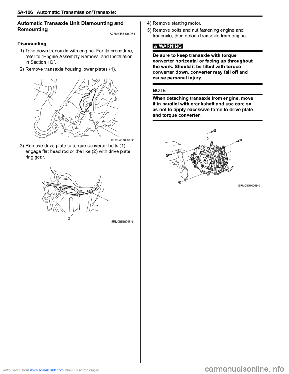
Dismounting1) Take down transaxle with engine. For its procedure, refer to “Engine Assembly Removal and Installation
in Section 1D”.
2) Remove transaxle housing lower plates (1).
3) Remove drive plate to torque converter bolts (1) engage flat head rod or the like (2) with drive plate
ring gear. 4) Remove starting motor.
5) Remove bolts and nut fastening engine and
transaxle, then detach transaxle from engine.WARNING!
Be sure to keep transaxle with torque
converter horizontal or facing up throughout
the work. Should it be tilted with torque
converter down, converter may fall off and
cause personal injury.
NOTE
When detaching transaxle from engine, move
it in parallel with cranks haft and use care so
as not to apply excessive force to drive plate
and torque converter.
1I4RS0A150004-01
I3RM0B510047-01
I3RM0B510049-01
Page 751 of 1496
Downloaded from www.Manualslib.com manuals search engine Automatic Transmission/Transaxle: 5A-107
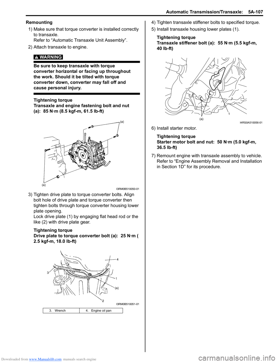
Remounting1) Make sure that torque converter is installed correctly to transaxle.
Refer to “Automatic Transaxle Unit Assembly”.
2) Attach transaxle to engine.
WARNING!
Be sure to keep transaxle with torque
converter horizontal or facing up throughout
the work. Should it be tilted with torque
converter down, converter may fall off and
cause personal injury.
Tightening torque
Transaxle and engine fastening bolt and nut
(a): 85 N·m (8.5 kgf-m, 61.5 lb-ft)
3) Tighten drive plate to torque converter bolts. Align bolt hole of drive plate and torque converter then
tighten bolts through torque converter housing lower
plate opening.
Lock drive plate (1) by engaging flat head rod or the
like (2) with drive plate gear.
Tightening torque
Drive plate to torque converter bolt (a): 25 N·m (
2.5 kgf-m, 18.0 lb-ft) 4) Tighten transaxle stiffener bolts to specified torque.
5) Install transaxle housing lower plates (1).
Tightening torque
Transaxle stiffener bolt (a): 55 N·m (5.5 kgf-m,
40 lb-ft)
6) Install starter motor. Tightening torque
Starter motor bolt and nut: 50 N·m (5.0 kgf-m,
36.5 lb-ft)
7) Remount engine with transaxle assembly to vehicle. Refer to “Engine Assembly Removal and Installation
in Section 1D” for its procedure.
3. Wrench 4. Engine oil pan
I3RM0B510050-01
I3RM0B510051-01
1
(a)
I4RS0A510056-01
Page 862 of 1496
Downloaded from www.Manualslib.com manuals search engine 5C-10 Clutch:
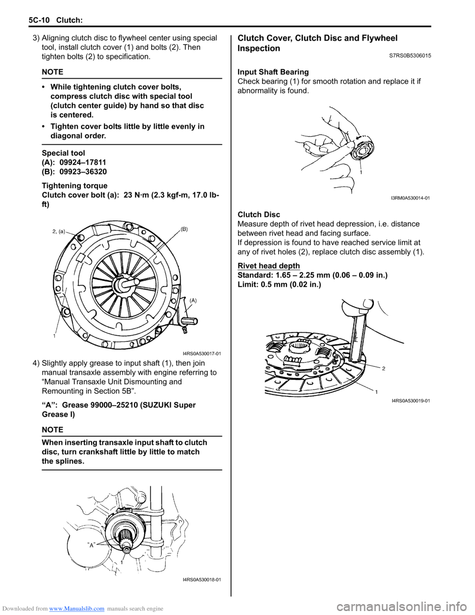
3) Aligning clutch disc to flywheel center using special
tool, install clutch cover (1) and bolts (2). Then
tighten bolts (2) to specification.
NOTE
• While tightening clutch cover bolts, compress clutch disc with special tool
(clutch center guide) by hand so that disc
is centered.
• Tighten cover bolts little by little evenly in diagonal order.
Special tool
(A): 09924–17811
(B): 09923–36320
Tightening torque
Clutch cover bolt (a): 23 N·m (2.3 kgf-m, 17.0 lb-
ft)
4) Slightly apply grease to input shaft (1), then join manual transaxle assembly with engine referring to
“Manual Transaxle Unit Dismounting and
Remounting in Section 5B”.
“A”: Grease 99000–25210 (SUZUKI Super
Grease I)
NOTE
When inserting transaxle input shaft to clutch
disc, turn crankshaft li ttle by little to match
the splines.
Clutch Cover, Clutch Disc and Flywheel
Inspection
S7RS0B5306015
Input Shaft Bearing
Check bearing (1) for smooth ro tation and replace it if
abnormality is found.
Clutch Disc
Measure depth of rivet head depression, i.e. distance
between rivet head and facing surface.
If depression is found to hav e reached service limit at
any of rivet holes (2), repl ace clutch disc assembly (1).
Rivet head depth
Standard: 1.65 – 2.25 mm (0.06 – 0.09 in.)
Limit: 0.5 mm (0.02 in.)
I4RS0A530017-01
I4RS0A530018-01
I3RM0A530014-01
I4RS0A530019-01
Page 881 of 1496
Downloaded from www.Manualslib.com manuals search engine Steering Wheel and Column: 6B-10
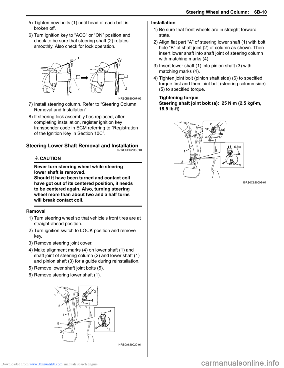
5) Tighten new bolts (1) until head of each bolt is broken off.
6) Turn ignition key to “ACC” or “ON” position and check to be sure that st eering shaft (2) rotates
smoothly. Also check for lock operation.
7) Install steering column. Re fer to “Steering Column
Removal and Installation”.
8) If steering lock assembly has replaced, after completing installation, register ignition key
transponder code in ECM referring to “Registration
of the Ignition Key in Section 10C”.
Steering Lower Shaft Removal and InstallationS7RS0B6206010
CAUTION!
Never turn steering wheel while steering
lower shaft is removed.
Should it have been turned and contact coil
have got out of its centered position, it needs
to be centered again. Also, turning steering
wheel more than about two and a half turns
will break contact coil.
Removal
1) Turn steering wheel so that vehicle’s front tires are at straight-ahead position.
2) Turn ignition switch to LOCK position and remove key.
3) Remove steering joint cover.
4) Make alignment marks (4) on lower shaft (1) and shaft joint of steering colu mn (2) and lower shaft (1)
and pinion shaft (3) for a guide during reinstallation.
5) Remove lower shaf t joint bolts (5).
6) Remove steering lower shaft (1). Installation
1) Be sure that front wheels are in straight forward state.
2) Align flat part “A” of steering lower shaft (1) with bolt hole “B” of shaft joint (2) of column as shown. Then
insert lower shaft into shaf t joint of steering column
with matching marks (4).
3) Insert lower shaft (1) into pinion shaft (3) with matching marks (4).
4) Tighten joint bolt (pinion shaft side) (6) to specified
torque first and then joint bolt (steering column side)
(5) to specified torque.
Tightening torque
Steering shaft joint bolt (a ): 25 N·m (2.5 kgf-m,
18.5 lb-ft)
I4RS0B620007-02
I4RS0A620020-01
I6RS0C620002-01
Page 969 of 1496
Downloaded from www.Manualslib.com manuals search engine Air Conditioning System: Manual Type 7B-21
Removal of Manifold Gauge Set
WARNING!
High pressure side is under high pressure.
Therefore, be careful not to get injured
especially on your eyes and skin.
For the A/C system charged with the specified amount of
refrigerant, remove manifold gauge set as follows:
1) Close low pressure side valve of manifold gauge set. (The high pressure side valve is closed continuously
during the process of charging.)
2) Close refrigerant container valve.
3) Stop engine.
4) Using shop rag, remove charging hoses from service valves. This operation must be performed quickly.
5) Put caps on service valves.
Check A/C System for Refrigerant Leaks
Whenever a refrigerant leak is suspected in the system
or any service operation has been performed which may
result in malfunction of lines and connections, it is
advisable to check for leaks.
Common sense should be used during refrigerant leak
test, since the need and extent of any such test will, in
general, depend upon the nature of a complaint and the
type of a service performed on the system.
Liquid leak detector
WARNING!
• To prevent explosions and fires, make sure that there are no flammables in the vicinity.
• When the refrigerant exposed to fire, it turns into a poisonous gas (phosgene). Do
not inhale this gas.
There is a number of fittings and places throughout the
A/C system where a liquid leak detector solution may be
used to pinpoint refrigerant leaks.
By merely applying the solution to the area in question
with a swab, such as attached to the cap of a vial,
bubbles will form within seconds if there is a leak.
For confined areas, such as sections of the evaporator
and condenser, an electronic (refrigerant) leak detector
is more practical fo r determining leaks.
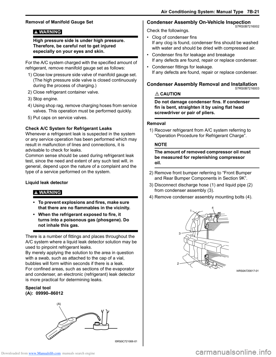
Special tool
(A): 09990–86012
Condenser Assembly On-Vehicle InspectionS7RS0B7216002
Check the followings.
• Clog of condenser fins If any clog is found, cond enser fins should be washed
with water and should be dried with compressed air.
• Condenser fins for leakage and breakage If any defects are found, repair or replace condenser.
• Condenser fittings for leakage. If any defects are found, repair or replace condenser.
Condenser Assembly Removal and InstallationS7RS0B7216003
CAUTION!
Do not damage condenser fins. If condenser
fin is bent, straighten it by using flat head
screwdriver or pair of pliers.
Removal
1) Recover refrigerant from A/C system referring to “Operation Procedure for Refrigerant Charge”.
NOTE
The amount of removed compressor oil must
be measured for replenishing compressor
oil.
2) Remove front bumper referring to “Front Bumper and Rear Bumper Components in Section 9K”.
3) Disconnect discharge hose (1) and liquid pipe (2) from condenser assembly (3).
4) Remove condenser assembly mounting bolts (4).
(A)
I5RS0C721006-01
4
1
3
2
I4RS0A720017-01
Page 1146 of 1496

Downloaded from www.Manualslib.com manuals search engine 8B-108 Air Bag System:
4) Remove side curtain-air bag (inflator) module fixing bolts (1) and clips (2).
5) Remove side curtain-air bag (inflator) module.
WARNING!
• When carrying a live air bag (inflator) module, make sure the bag opening is
pointed away from you.
Never carry air bag (inflator) module by
wires or connector on the side of the
module. In case of an accidental
deployment, the bag will then deploy with
minimal chance of injury.
• As the live curtain air bag (inflator) module must be kept with it s bag facing up while
being stored or left standing. This is
necessary so that a free space is provided
to allow the air bag to expand in the
unlikely event of accidental deployment.
• Observe “Precautions on Handling and Storage of Air Bag System Components”
for handling and storing it.
Otherwise, personal injury may result.
Installation
WARNING!
Do not install side curtain-air bag (inflator)
module while twisted or bended. Otherwise,
side curtain-air bag (inflator) module may not
deploy and injury may result.
1) Install side curtain-air bag (inflator) module (1) with
clips and new bolts.
2) Tighten side curtain-air bag (inflator) module attaching bolts (1) to specified torque.
Tightening torque
Side curtain-air bag (inflator) module attaching
bolts (a): 11 N·m (1.1 kgf-m, 8.0 lb-ft)
3) Connect side curtain-air bag (inflator) module connector (1) securely as shown in figure.
a) Connect connector.
b) Lock connector wi th lock button (2).
4) Install head lining referring to “Head Lining Removal and Installation in Section 9H”.
5) Enable air bag system. Refer to “Enabling Air Bag System”.1 2
2
22
1
I4RS0A820076-01
1,(a) 1,(a)
I4RS0A820110-01
1
2
a)
b)
I4RS0A820055-01
Page 1163 of 1496
Downloaded from www.Manualslib.com manuals search engine Air Bag System: 8B-125
Specifications
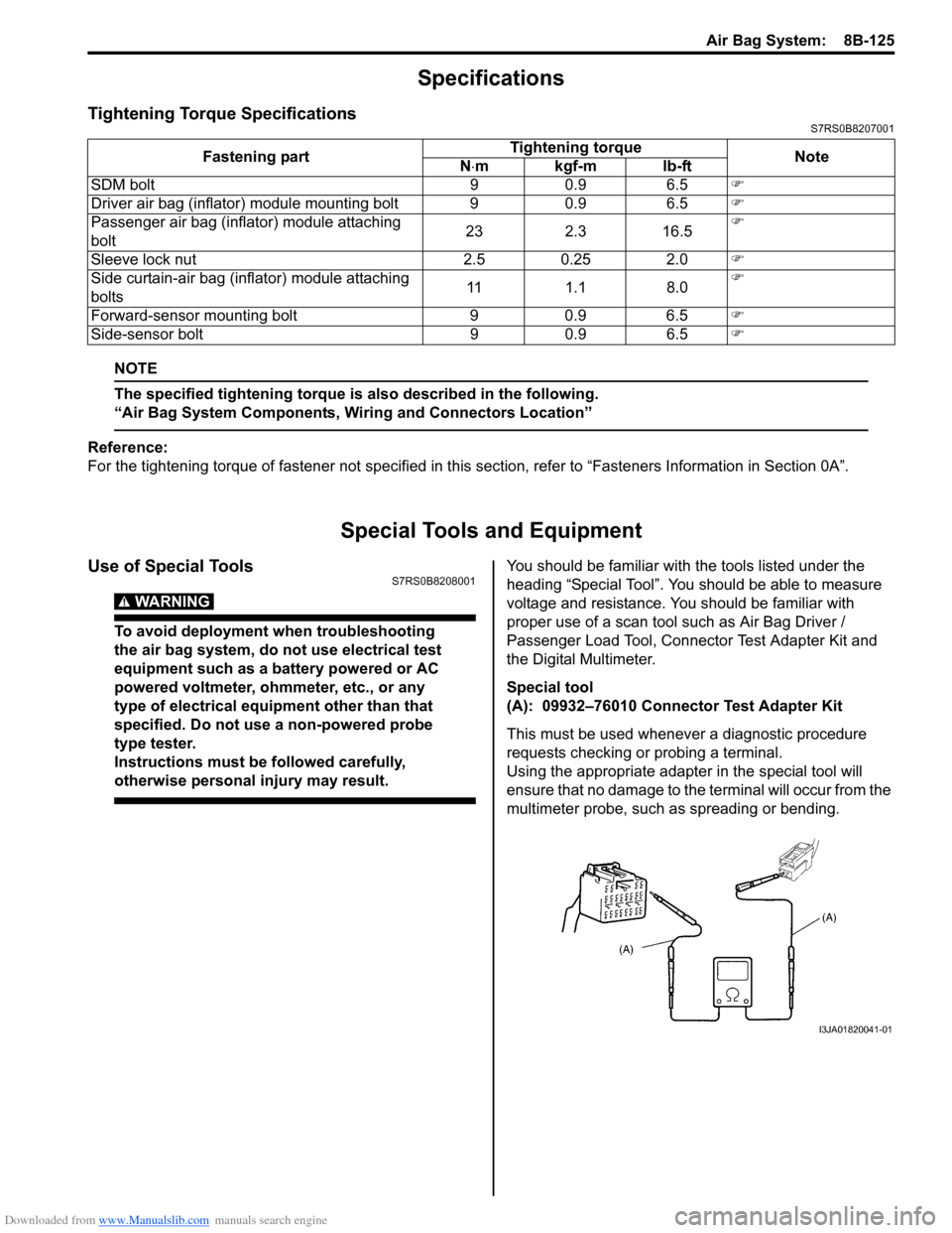
Tightening Torque SpecificationsS7RS0B8207001
NOTE
The specified tightening torque is also described in the following.
“Air Bag System Components, Wiring and Connectors Location”
Reference:
For the tightening torque of fastener not specified in this section, refer to “Fasteners Information in Section 0A”.
Special Tools and Equipment
Use of Special ToolsS7RS0B8208001
WARNING!
To avoid deployment when troubleshooting
the air bag system, do not use electrical test
equipment such as a battery powered or AC
powered voltmeter, ohmmeter, etc., or any
type of electrical equipment other than that
specified. Do not use a non-powered probe
type tester.
Instructions must be followed carefully,
otherwise personal injury may result.
You should be familiar with the tools listed under the
heading “Special Tool”. You should be able to measure
voltage and resistance. You should be familiar with
proper use of a scan tool such as Air Bag Driver /
Passenger Load Tool, Connector Test Adapter Kit and
the Digital Multimeter.
Special tool
(A): 09932–76010 Connector Test Adapter Kit
This must be used whenever a diagnostic procedure
requests checking or probing a terminal.
Using the appropriate adapter in the special tool will
ensure that no damage to the terminal will occur from the
multimeter probe, such as spreading or bending.
Fastening part
Tightening torque
Note
N ⋅mkgf-mlb-ft
SDM bolt 9 0.9 6.5 �)
Driver air bag (inflator) module mounting bolt 9 0.9 6.5 �)
Passenger air bag (inflator) module attaching
bolt 23 2.3 16.5�)
Sleeve lock nut 2.5 0.25 2.0 �)
Side curtain-air bag (inflator) module attaching
bolts 11 1.1 8.0�)
Forward-sensor mounting bolt 9 0.9 6.5 �)
Side-sensor bolt 9 0.9 6.5 �)
I3JA01820041-01
Page 1287 of 1496
Downloaded from www.Manualslib.com manuals search engine Lighting Systems: 9B-5
Interior Light Symptom DiagnosisS7RS0B9204008
NOTE
• Use of SUZUKI scan tool makes it easy to check whether a faulty condition is on the input side or
output side of BCM. For checking procedure, re fer to “Diagnosis Using Output Test Function of
SUZUKI Scan Tool” under “Scan Tool Data in Section 10B”.
• Check each part in the order from the top of the following list.
Repair Instructions
Headlight Housing Removal and InstallationS7RS0B9206001
Removal 1) Disconnect negative (–) cable at battery.
2) Remove front bumper. Refer to “Front Bumper and Rear Bumper Componen ts in Section 9K”.
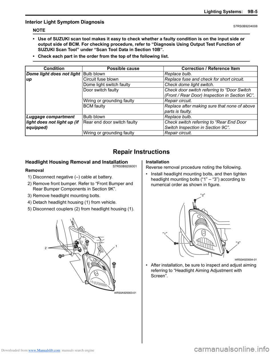
3) Remove headlight mounting bolts.
4) Detach headlight housing (1) from vehicle.
5) Disconnect couplers (2) from headlight housing (1). Installation
Reverse removal procedure noting the following.
• Install headlight mounting bolts, and then tighten
headlight mounting bolts (“1” – “3”) according to
numerical order as shown in figure.
• After installation, be sure to inspect and adjust aiming referring to “Headlight Aiming Adjustment with
Screen”.
Condition Possible cause Correction / Reference Item
Dome light does not light
up Bulb blown
Replace bulb.
Circuit fuse blown Replace fuse and check for short circuit.
Dome light switch faulty Check dome light switch.
Door switch faulty Check door switch referring to “Door Switch
(Front / Rear Door) Inspection in Section 9C”.
Wiring or grounding faulty Repair circuit.
BCM faulty Replace after making sure that none of above
parts is faulty.
Luggage compartment
light does not light up (if
equipped) Bulb blown
Replace bulb.
Rear end door switch faulty Check switch referring to “Rear End Door
Switch Inspection in Section 9C”.
Wiring or grounding faulty Repair circuit.
2 1
I4RS0A920003-01
2
1 3
I4RS0A920004-01
Page 1357 of 1496
Downloaded from www.Manualslib.com manuals search engine Security and Locks: 9F-11
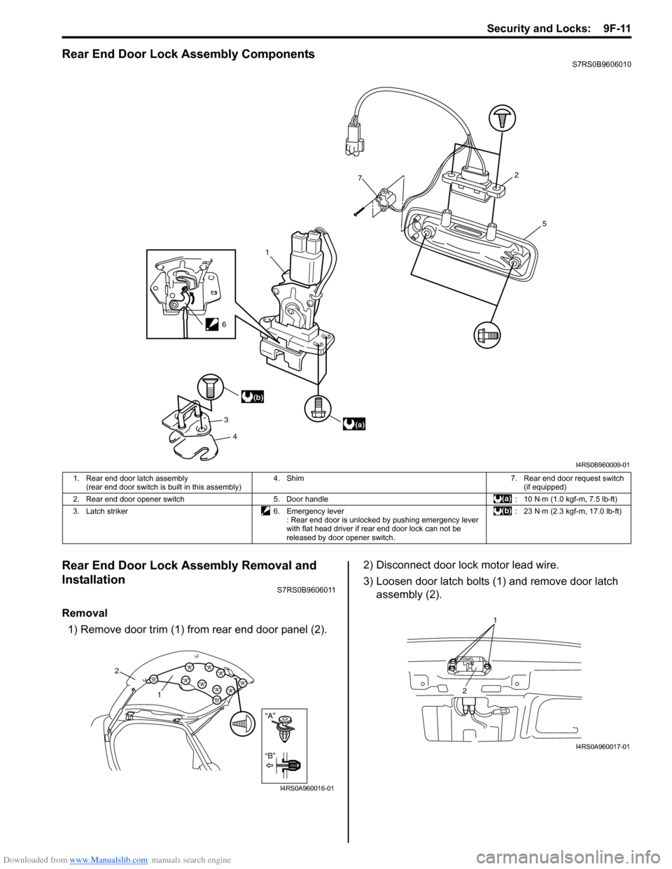
Rear End Door Lock Assembly ComponentsS7RS0B9606010
Rear End Door Lock Assembly Removal and
Installation
S7RS0B9606011
Removal1) Remove door trim (1) from rear end door panel (2). 2) Disconnect door lock motor lead wire.
3) Loosen door latch bolts (1) and remove door latch
assembly (2).
1
7
3 4 5
2
(a)
(b)
6
I4RS0B960009-01
1. Rear end door latch assembly
(rear end door switch is built in this assembly) 4. Shim 7. Rear end door request switch
(if equipped)
2. Rear end door opener switch 5. Door handle : 10 N⋅ m (1.0 kgf-m, 7.5 lb-ft)
3. Latch striker 6. Emergency lever : Rear end door is unlocked by pushing emergency lever
with flat head driver if rear end door lock can not be
released by door opener switch. :23 N
⋅m (2.3 kgf-m, 17.0 lb-ft)
“A”
“B”
“B”
“A”“B”“A”“A”“A”
“A”“A”“A”
“A”
2
1
I4RS0A960016-01
1
2
I4RS0A960017-01