Ignition output wiring SUZUKI SWIFT 2007 2.G Service Owner's Manual
[x] Cancel search | Manufacturer: SUZUKI, Model Year: 2007, Model line: SWIFT, Model: SUZUKI SWIFT 2007 2.GPages: 1496, PDF Size: 34.44 MB
Page 211 of 1496
Downloaded from www.Manualslib.com manuals search engine Engine General Information and Diagnosis: 1A-161
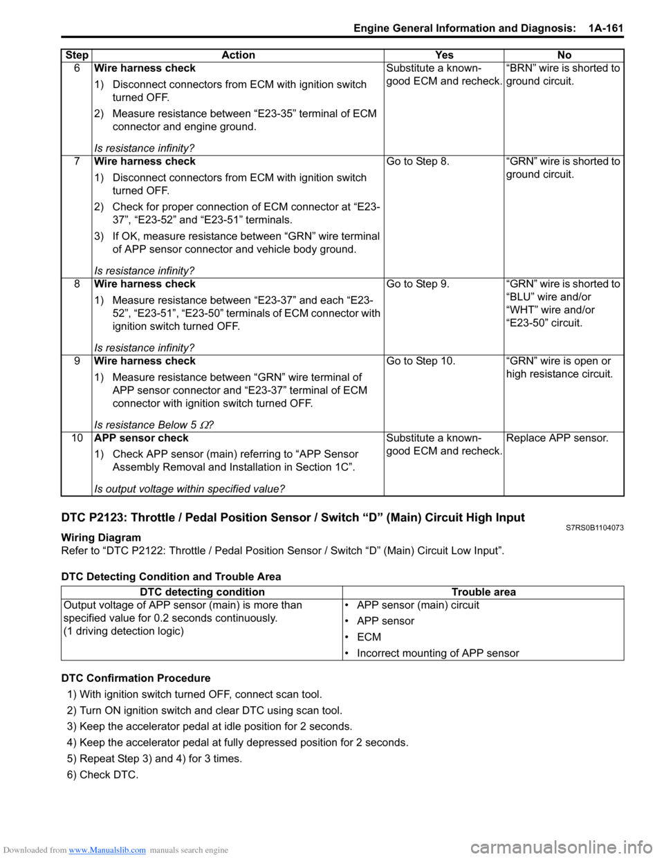
DTC P2123: Throttle / Pedal Position Sensor / Switch “D” (Main) Circuit High InputS7RS0B1104073
Wiring Diagram
Refer to “DTC P2122: Throttle / Pedal Position Sensor / Switch “D” (Main) Circuit Low Input”.
DTC Detecting Condition and Trouble Area
DTC Confirmation Procedure 1) With ignition switch turned OFF, connect scan tool.
2) Turn ON ignition switch and clear DTC using scan tool.
3) Keep the accelerator pedal at idle position for 2 seconds.
4) Keep the accelerator pedal at fully depressed position for 2 seconds.
5) Repeat Step 3) and 4) for 3 times.
6) Check DTC. 6
Wire harness check
1) Disconnect connectors from ECM with ignition switch
turned OFF.
2) Measure resistance between “E23-35” terminal of ECM connector and engine ground.
Is resistance infinity? Substitute a known-
good ECM and recheck.
“BRN” wire is shorted to
ground circuit.
7 Wire harness check
1) Disconnect connectors from ECM with ignition switch
turned OFF.
2) Check for proper connection of ECM connector at “E23- 37”, “E23-52” and “E23-51” terminals.
3) If OK, measure resistance between “GRN” wire terminal of APP sensor connector and vehicle body ground.
Is resistance infinity? Go to Step 8. “GRN” wire is shorted to
ground circuit.
8 Wire harness check
1) Measure resistance between “E23-37” and each “E23-
52”, “E23-51”, “E23-50” terminals of ECM connector with
ignition switch turned OFF.
Is resistance infinity? Go to Step 9. “GRN” wire is shorted to
“BLU” wire and/or
“WHT” wire and/or
“E23-50” circuit.
9 Wire harness check
1) Measure resistance between “GRN” wire terminal of
APP sensor connector and “E23-37” terminal of ECM
connector with ignition switch turned OFF.
Is resistance Below 5
Ω? Go to Step 10. “GRN” wire is open or
high resistance circuit.
10 APP sensor check
1) Check APP sensor (main) re ferring to “APP Sensor
Assembly Removal and Inst allation in Section 1C”.
Is output voltage within specified value? Substitute a known-
good ECM and recheck.
Replace APP sensor.
Step Action Yes No
DTC detecting condition
Trouble area
Output voltage of APP sensor (main) is more than
specified value for 0.2 seconds continuously.
(1 driving detection logic) • APP sensor (main) circuit
• APP sensor
•ECM
• Incorrect mounting of APP sensor
Page 214 of 1496
Downloaded from www.Manualslib.com manuals search engine 1A-164 Engine General Information and Diagnosis:
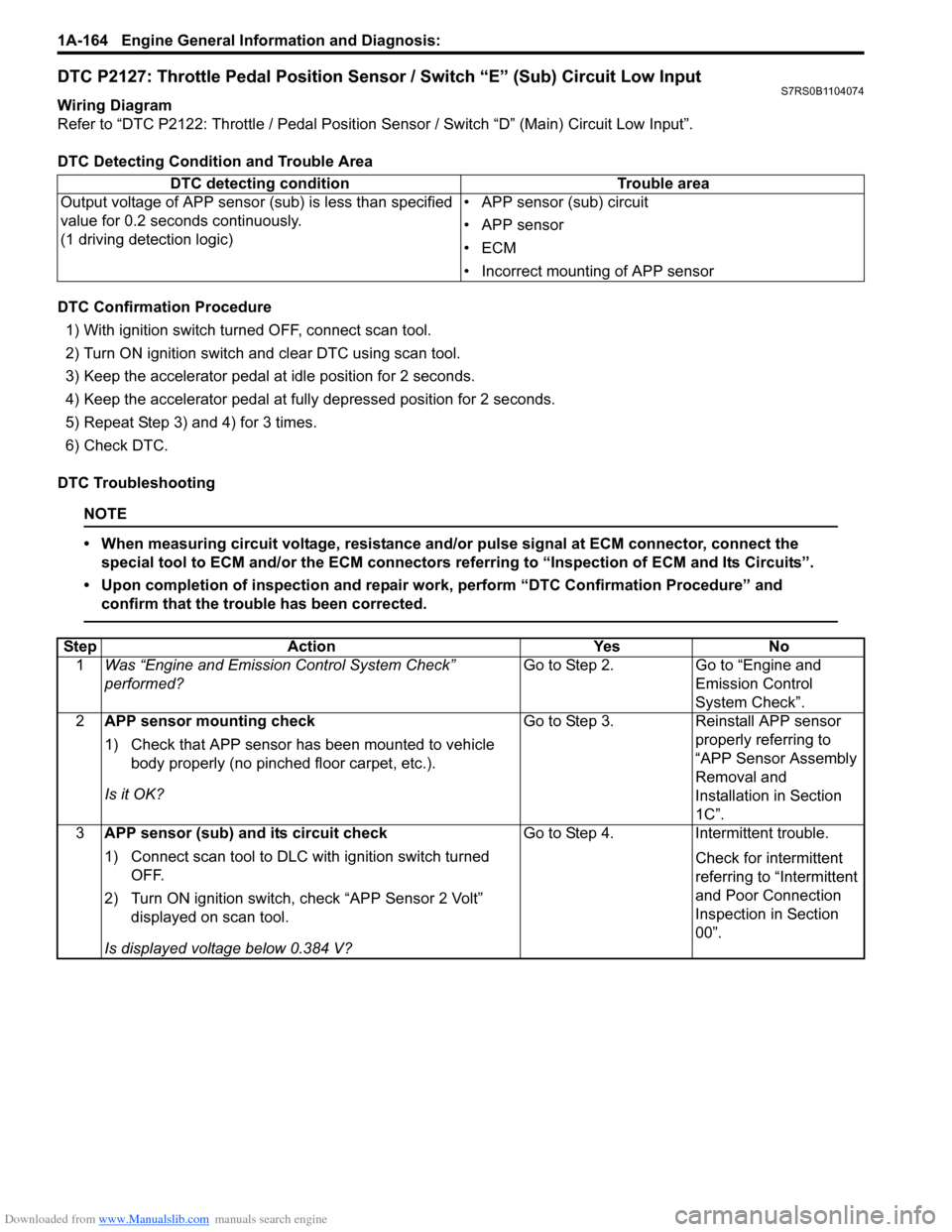
DTC P2127: Throttle Pedal Position Sensor / Switch “E” (Sub) Circuit Low InputS7RS0B1104074
Wiring Diagram
Refer to “DTC P2122: Throttle / Pedal Position Sensor / Switch “D” (Main) Circuit Low Input”.
DTC Detecting Condition and Trouble Area
DTC Confirmation Procedure 1) With ignition switch turned OFF, connect scan tool.
2) Turn ON ignition switch and clear DTC using scan tool.
3) Keep the accelerator pedal at idle position for 2 seconds.
4) Keep the accelerator pedal at fully depressed position for 2 seconds.
5) Repeat Step 3) and 4) for 3 times.
6) Check DTC.
DTC Troubleshooting
NOTE
• When measuring circuit voltage, resistance and/ or pulse signal at ECM connector, connect the
special tool to ECM and/or the ECM connectors re ferring to “Inspection of ECM and Its Circuits”.
• Upon completion of inspection and repair work, perform “DTC Confirmation Procedure” and confirm that the trouble has been corrected.
DTC detecting condition Trouble area
Output voltage of APP sensor (sub) is less than specified
value for 0.2 seconds continuously.
(1 driving detection logic) • APP sensor (sub) circuit
• APP sensor
•ECM
• Incorrect mounting of APP sensor
Step
Action YesNo
1 Was “Engine and Emission Control System Check”
performed? Go to Step 2.
Go to “Engine and
Emission Control
System Check”.
2 APP sensor mounting check
1) Check that APP sensor has been mounted to vehicle
body properly (no pinched floor carpet, etc.).
Is it OK? Go to Step 3.
Reinstall APP sensor
properly referring to
“APP Sensor Assembly
Removal and
Installation in Section
1C”.
3 APP sensor (sub) and its circuit check
1) Connect scan tool to DLC with ignition switch turned
OFF.
2) Turn ON ignition switch, check “APP Sensor 2 Volt” displayed on scan tool.
Is displayed voltage below 0.384 V? Go to Step 4.
Intermittent trouble.
Check for intermittent
referring to “Intermittent
and Poor Connection
Inspection in Section
00”.
Page 216 of 1496
Downloaded from www.Manualslib.com manuals search engine 1A-166 Engine General Information and Diagnosis:
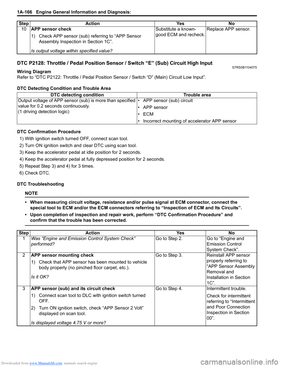
DTC P2128: Throttle / Pedal Position Sensor / Switch “E” (Sub) Circuit High InputS7RS0B1104075
Wiring Diagram
Refer to “DTC P2122: Throttle / Pedal Position Sensor / Switch “D” (Main) Circuit Low Input”.
DTC Detecting Condition and Trouble Area
DTC Confirmation Procedure 1) With ignition switch turned OFF, connect scan tool.
2) Turn ON ignition switch and clear DTC using scan tool.
3) Keep the accelerator pedal at idle position for 2 seconds.
4) Keep the accelerator pedal at fully depressed position for 2 seconds.
5) Repeat Step 3) and 4) for 3 times.
6) Check DTC.
DTC Troubleshooting
NOTE
• When measuring circuit voltage, resistance and/ or pulse signal at ECM connector, connect the
special tool to ECM and/or the ECM connectors re ferring to “Inspection of ECM and Its Circuits”.
• Upon completion of inspection and repair work, perform “DTC Confirmation Procedure” and confirm that the trouble has been corrected.
10 APP sensor check
1) Check APP sensor (sub) re ferring to “APP Sensor
Assembly Inspection in Section 1C”.
Is output voltage within specified value? Substitute a known-
good ECM and recheck.
Replace APP sensor.
Step Action Yes No
DTC detecting condition
Trouble area
Output voltage of APP sensor (s ub) is more than specified
value for 0.2 seconds continuously.
(1 driving detection logic) • APP sensor (sub) circuit
• APP sensor
•ECM
• Incorrect mounting of
accelerator APP sensor
Step Action YesNo
1 Was “Engine and Emission Control System Check”
performed? Go to Step 2.
Go to “Engine and
Emission Control
System Check”.
2 APP sensor mounting check
1) Check that APP sensor has been mounted to vehicle
body properly (no pinched floor carpet, etc.).
Is it OK? Go to Step 3.
Reinstall APP sensor
properly referring to
“APP Sensor Assembly
Removal and
Installation in Section
1C”.
3 APP sensor (sub) and its circuit check
1) Connect scan tool to DLC with ignition switch turned
OFF.
2) Turn ON ignition switch, check “APP Sensor 2 Volt” displayed on scan tool.
Is displayed voltage 4.75 V or more? Go to Step 4.
Intermittent trouble.
Check for intermittent
referring to “Intermittent
and Poor Connection
Inspection in Section
00”.
Page 218 of 1496
Downloaded from www.Manualslib.com manuals search engine 1A-168 Engine General Information and Diagnosis:
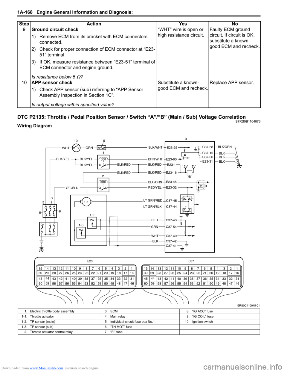
DTC P2135: Throttle / Pedal Position Sensor / Switch “A”/“B” (Main / Sub) Voltage CorrelationS7RS0B1104076
Wiring Diagram9
Ground circuit check
1) Remove ECM from its br acket with ECM connectors
connected.
2) Check for proper connection of ECM connector at “E23- 51” terminal.
3) If OK, measure resistance between “E23-51” terminal of ECM connector and engine ground.
Is resistance below 5
Ω? “WHT” wire is open or
high resistance circuit.
Faulty ECM ground
circuit. If circuit is OK,
substitute a known-
good ECM and recheck.
10 APP sensor check
1) Check APP sensor (sub) re ferring to “APP Sensor
Assembly Inspection in Section 1C”.
Is output voltage within specified value? Substitute a known-
good ECM and recheck.
Replace APP sensor.
Step Action Yes No
E23
C37
34
1819
567
1011
17
20
47 46
495051
2122
52 16
25 9
24
14
29
55
57 54 53
59
60 58 2
262728
15
30
56 4832 31
34353637
40
42 39 38
44
45 43 41 331
1213
238
34
1819
567
1011
17
20
47 46
495051
2122
52 16
25 9
24
14
29
55
57 54 53
59
60 58 2
262728
15
30
56 4832 31
34353637
40
42 39 38
44
45 43 41 331
1213
238
12V
5VBLK/REDBLK/RED
BLK/YEL
12BLK/YEL
BLK/YEL
BRN/WHT
E23-1
E23-60
C37-58
C37-15 C37-30
BLK/ORN
BLKBLKE23-31 BLK
BLK/RED
BLU/ORN
RED/YELYEL/BLU
LT GRN/RED
LT GRN/BLK
RED
GRN
WHT
BLK
E23-16
E23-45
E23-32
C37-45
C37-44
C37-41C37-42
C37-40
C37-54
C37-43
1-1
1-2
1-3 3
4
5
8 67
10
9
E23-29 GRNBLK/WHTWHT
BLK/RED
I6RS0C110045-01
1. Electric throttle body assembly
3. ECM 8. “IG ACC” fuse
1-1. Throttle actuator 4. Main relay9. “IG COIL” fuse
1-2. TP sensor (main) 5. Individual circuit fuse box No.110. Ignition switch
1-3. TP sensor (sub) 6. “TH MOT” fuse
2. Throttle actuator control relay 7. “FI” fuse
Page 414 of 1496
Downloaded from www.Manualslib.com manuals search engine 1J-4 Charging System:
Diagnostic Information and Procedures
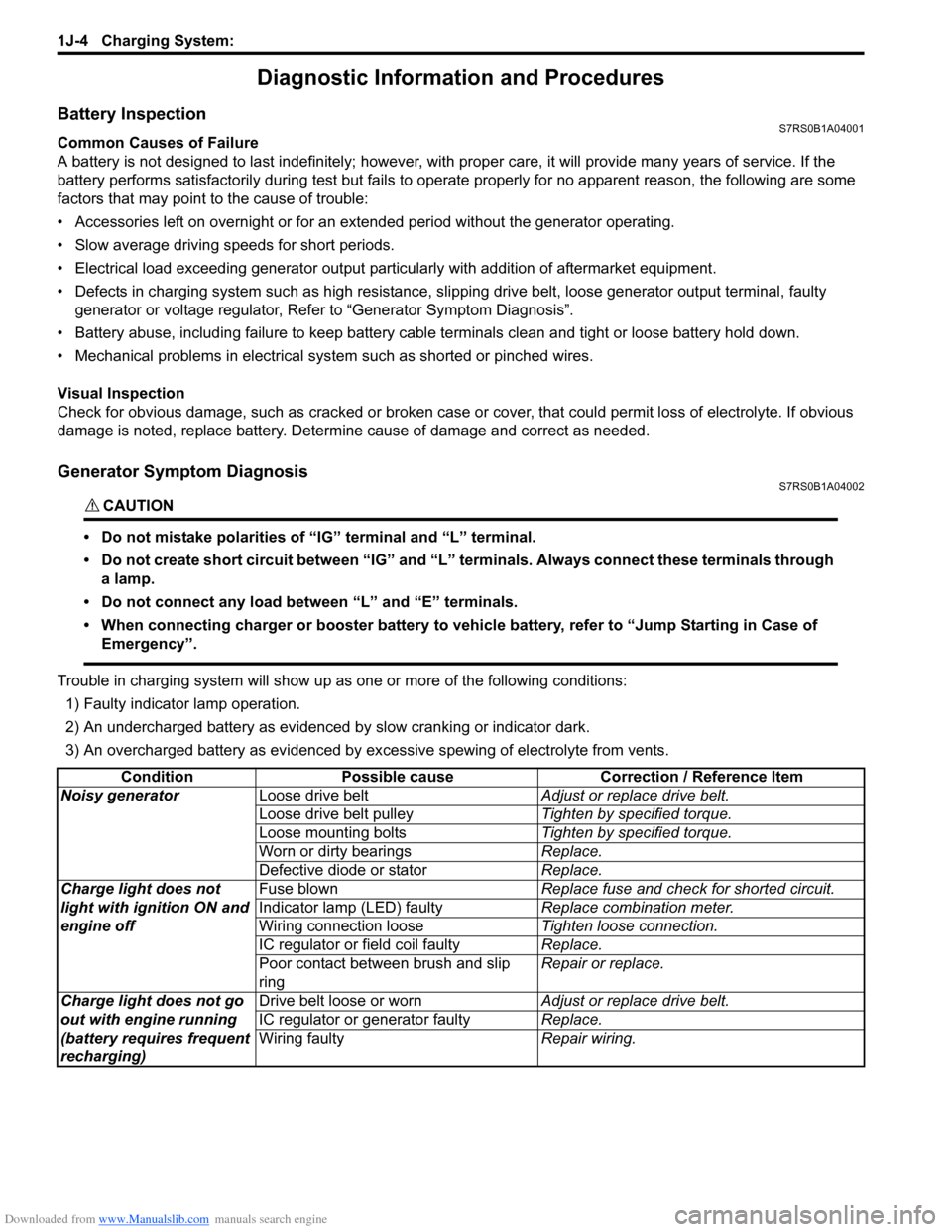
Battery InspectionS7RS0B1A04001
Common Causes of Failure
A battery is not designed to last indefinitely; however, with proper care, it will provide many years of service. If the
battery performs satisfactorily during te st but fails to operate properly for no apparent reason, the following are some
factors that may point to the cause of trouble:
• Accessories left on overnight or for an extended period without the generator operating.
• Slow average driving speeds for short periods.
• Electrical load exceeding generator output partic ularly with addition of aftermarket equipment.
• Defects in charging system such as high resistance, s lipping drive belt, loose generator output terminal, faulty
generator or voltage regulator, Refer to “Generator Symptom Diagnosis”.
• Battery abuse, including failure to keep battery cable terminals clean and tight or loose battery hold down.
• Mechanical problems in electrical sys tem such as shorted or pinched wires.
Visual Inspection
Check for obvious damage, such as cracked or broken case or cover, that could permit loss of electrolyte. If obvious
damage is noted, replace battery. Determine cause of damage and correct as needed.
Generator Symptom DiagnosisS7RS0B1A04002
CAUTION!
• Do not mistake polarities of “IG” terminal and “L” terminal.
• Do not create short circuit between “IG” and “L” terminals. Always connect these terminals through a lamp.
• Do not connect any load between “L” and “E” terminals.
• When connecting charger or booster battery to vehicle battery, refer to “Jump Starting in Case of Emergency”.
Trouble in charging system will show up as one or more of the following conditions:
1) Faulty indicator lamp operation.
2) An undercharged battery as evidenced by slow cranking or indicator dark.
3) An overcharged battery as evidenced by ex cessive spewing of electrolyte from vents.
Condition Possible cause Correction / Reference Item
Noisy generator Loose drive belt Adjust or replace drive belt.
Loose drive belt pulley Tighten by specified torque.
Loose mounting bolts Tighten by specified torque.
Worn or dirty bearings Replace.
Defective diode or stator Replace.
Charge light does not
light with ignition ON and
engine off Fuse blown
Replace fuse and check for shorted circuit.
Indicator lamp (LED) faulty Replace combination meter.
Wiring connection loose Tighten loose connection.
IC regulator or field coil faulty Replace.
Poor contact between brush and slip
ring Repair or replace.
Charge light does not go
out with engine running
(battery requires frequent
recharging) Drive belt loose or worn
Adjust or replace drive belt.
IC regulator or generator faulty Replace.
Wiring faulty Repair wiring.
Page 559 of 1496
Downloaded from www.Manualslib.com manuals search engine ABS: 4E-20
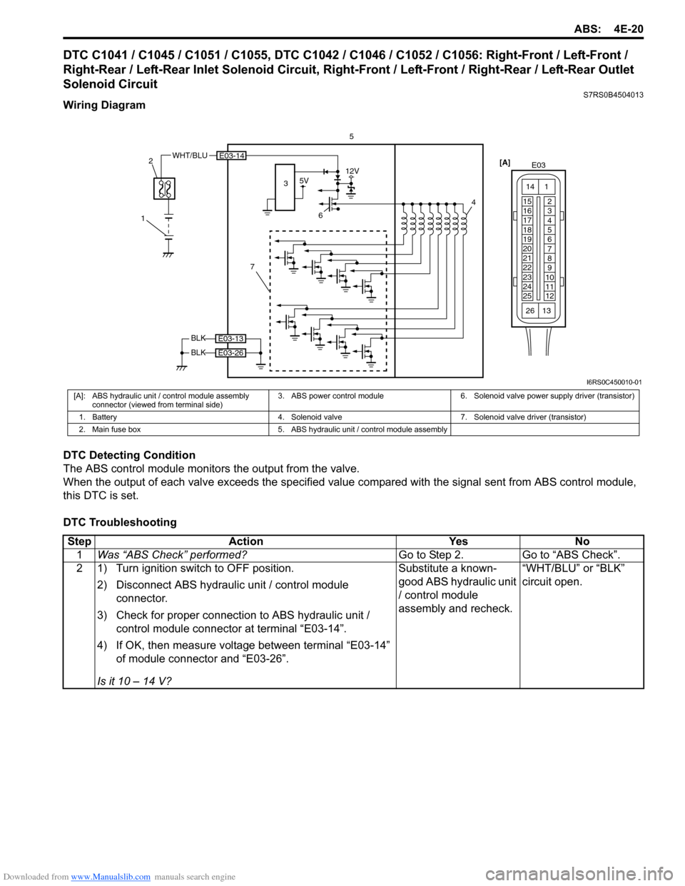
DTC C1041 / C1045 / C1051 / C1055, DTC C1042 / C1046 / C1052 / C1056: Right-Front / Left-Front /
Right-Rear / Left-Rear Inlet Solenoid Circuit, Right-Front / Left-Front / Right-Rear / Left-Rear Outlet
Solenoid Circuit
S7RS0B4504013
Wiring Diagram
DTC Detecting Condition
The ABS control module monitors the output from the valve.
When the output of each valve exceeds the specified value compared with the signal sent from ABS control module,
this DTC is set.
DTC Troubleshooting
6 4
E03-14
5V12V
7
3
WHT/BLU
1 2
5
BLK
BLK
E03-13
E03-26
[A]
E03
15
16
17
18
19
20
21
22
23
24
25 2
3
4
5
6
7
8
9
10
11
12
1
13
14
26
I6RS0C450010-01
[A]: ABS hydraulic unit / control module assembly
connector (viewed from terminal side) 3. ABS power control module 6. Solenoid valve power supply driver (transistor)
1. Battery 4. Solenoid valve 7. Solenoid valve driver (transistor)
2. Main fuse box 5. ABS hydraulic unit / control module assembly
Step Action YesNo
1 Was “ABS Check” performed? Go to Step 2.Go to “ABS Check”.
2 1) Turn ignition switch to OFF position.
2) Disconnect ABS hydraulic unit / control module connector.
3) Check for proper connection to ABS hydraulic unit / control module connector at terminal “E03-14”.
4) If OK, then measure voltage between terminal “E03-14” of module connector and “E03-26”.
Is it 10 – 14 V? Substitute a known-
good ABS hydraulic unit
/ control module
assembly and recheck.
“WHT/BLU” or “BLK”
circuit open.
Page 608 of 1496
Downloaded from www.Manualslib.com manuals search engine 4F-34 Electronic Stability Program:
DTC C1024: Steering Angle Sensor Circuit FailureS7RS0B4604029
DTC Detecting Condition and Trouble Area
DTC Troubleshooting
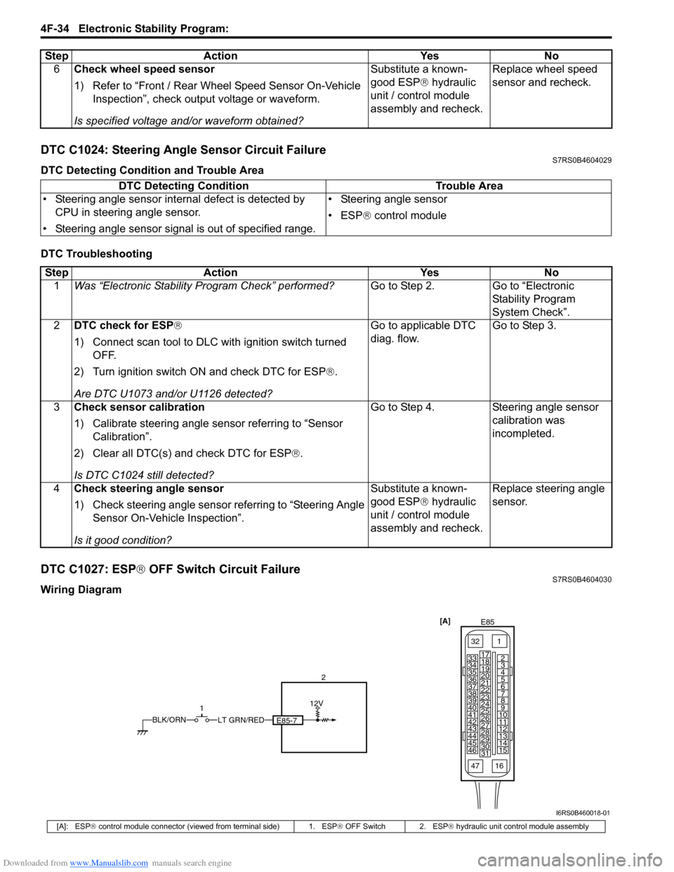
DTC C1027: ESP® OFF Switch Circuit FailureS7RS0B4604030
Wiring Diagram 6
Check wheel speed sensor
1) Refer to “Front / Rear Wheel Speed Sensor On-Vehicle
Inspection”, check output voltage or waveform.
Is specified voltage and/or waveform obtained? Substitute a known-
good ESP
® hydraulic
unit / control module
assembly and recheck. Replace wheel speed
sensor and recheck.
Step
Action YesNo
DTC Detecting Condition Trouble Area
• Steering angle sensor internal defect is detected by CPU in steering angle sensor.
• Steering angle sensor signal is out of specified range. • Steering angle sensor
• ESP
® control module
Step Action YesNo
1 Was “Electronic Stability Pr ogram Check” performed? Go to Step 2.Go to “Electronic
Stability Program
System Check”.
2 DTC check for ESP®
1) Connect scan tool to DLC with ignition switch turned
OFF.
2) Turn ignition switch ON and check DTC for ESP ®.
Are DTC U1073 and/or U1126 detected? Go to applicable DTC
diag. flow.
Go to Step 3.
3 Check sensor calibration
1) Calibrate steering angle sensor referring to “Sensor
Calibration”.
2) Clear all DTC(s) and check DTC for ESP ®.
Is DTC C1024 still detected? Go to Step 4.
Steering angle sensor
calibration was
incompleted.
4 Check steering angle sensor
1) Check steering angle sensor referring to “Steering Angle
Sensor On-Vehicle Inspection”.
Is it good condition? Substitute a known-
good ESP
® hydraulic
unit / control module
assembly and recheck. Replace steering angle
sensor.
[A]
E85
161
15
2
3
4
5
6
7
8
9
10
11
12
13
14
17
18
19
20
21
22
23
24
25
26
27
28
29
30
31
3233
34
35
36
37
38
39
40
41
42
43
44
45
46
47
LT GRN/REDBLK/ORN
12V
E85-7
1 2
I6RS0B460018-01
[A]: ESP
® control module connector (viewed from terminal side) 1. ESP ® OFF Switch 2. ESP ® hydraulic unit control module assembly
Page 614 of 1496
Downloaded from www.Manualslib.com manuals search engine 4F-40 Electronic Stability Program:
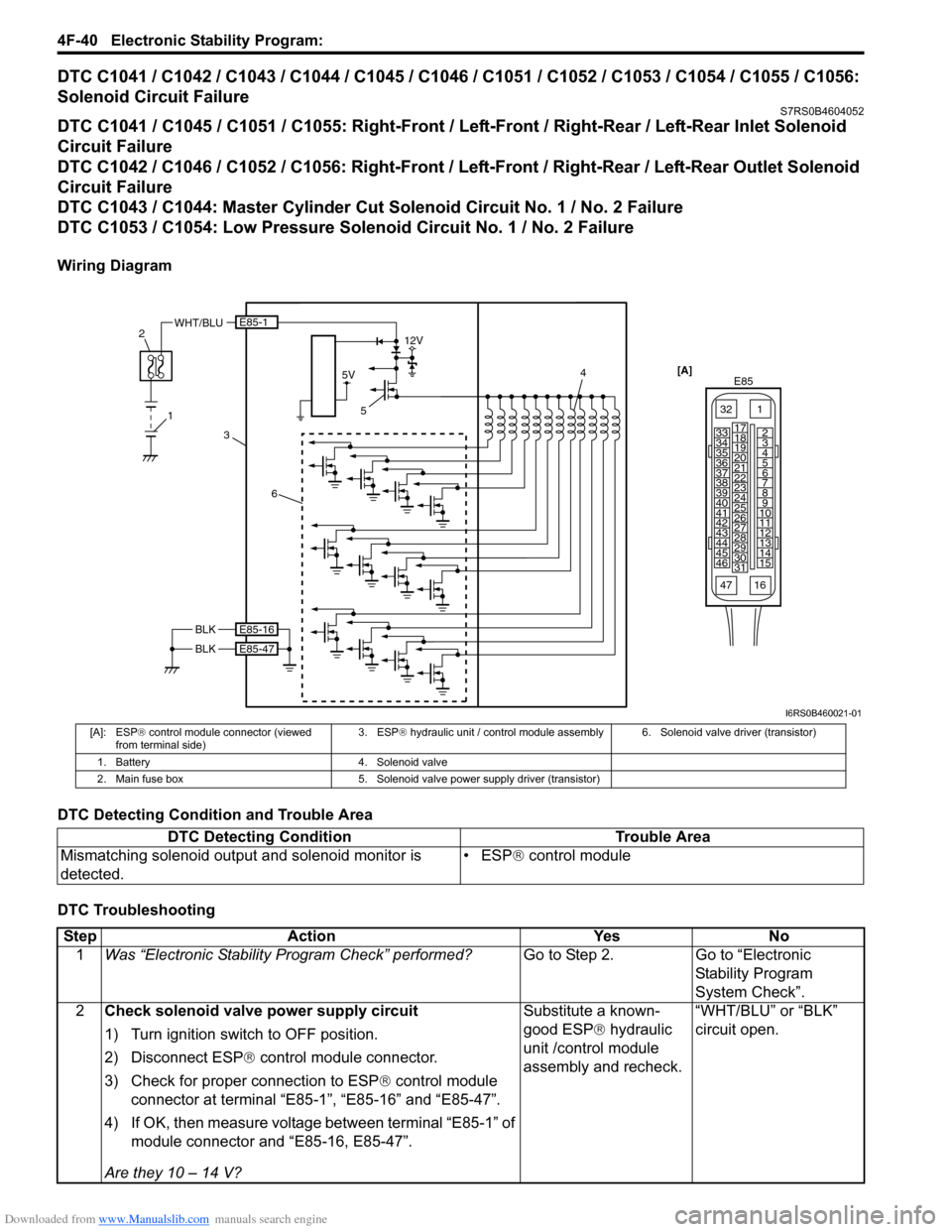
DTC C1041 / C1042 / C1043 / C1044 / C1045 / C1046 / C1051 / C1052 / C1053 / C1054 / C1055 / C1056:
Solenoid Circuit Failure
S7RS0B4604052
DTC C1041 / C1045 / C1051 / C1055: Right-Front / Left-Front / Right-Rear / Left-Rear Inlet Solenoid
Circuit Failure
DTC C1042 / C1046 / C1052 / C1056: Right-Front / Left-Front / Right-Rear / Left-Rear Outlet Solenoid
Circuit Failure
DTC C1043 / C1044: Master Cylinder Cut Solenoid Circuit No. 1 / No. 2 Failure
DTC C1053 / C1054: Low Pressure Solenoid Circuit No. 1 / No. 2 Failure
Wiring Diagram
DTC Detecting Condition and Trouble Area
DTC Troubleshooting
[A]E85
161
15
2
3
4
5
6
7
8
9
10
11
12
13
14
17
18
19
20
21
22
23
24
25
26
27
28
29
30
31
3233
34
35
36
37
38
39
40
41
42
43
44
45
46
47
WHT/BLU
1
2
54
BLK
BLK
5V
12V
E85-1
E85-16
E85-47
6
3
I6RS0B460021-01
[A]: ESP
® control module connector (viewed
from terminal side) 3. ESP
® hydraulic unit / control module assemb ly 6. Solenoid valve driver (transistor)
1. Battery 4. Solenoid valve
2. Main fuse box 5. Solenoid valve power supply driver (transistor)
DTC Detecting Condition Trouble Area
Mismatching solenoid output and solenoid monitor is
detected. • ESP
® control module
Step Action YesNo
1 Was “Electronic Stability Pr ogram Check” performed? Go to Step 2.Go to “Electronic
Stability Program
System Check”.
2 Check solenoid valve power supply circuit
1) Turn ignition switch to OFF position.
2) Disconnect ESP ® control module connector.
3) Check for proper connection to ESP ® control module
connector at terminal “E85-1”, “E85-16” and “E85-47”.
4) If OK, then measure voltage between terminal “E85-1” of module connector and “E85-16, E85-47”.
Are they 10 – 14 V? Substitute a known-
good ESP
® hydraulic
unit /control module
assembly and recheck. “WHT/BLU” or “BLK”
circuit open.
Page 617 of 1496
Downloaded from www.Manualslib.com manuals search engine Electronic Stability Program: 4F-43
DTC Troubleshooting
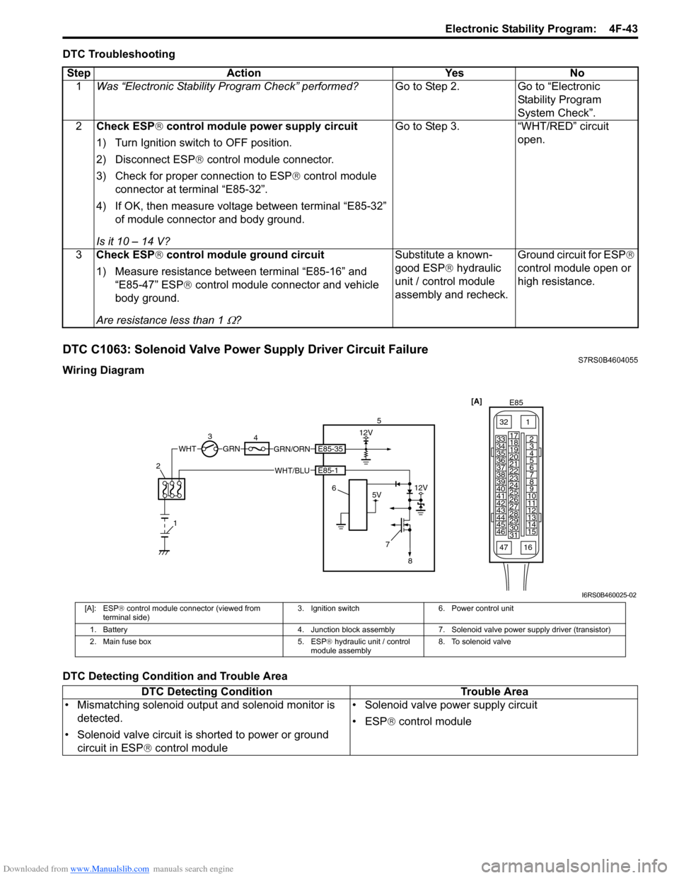
DTC C1063: Solenoid Valve Power Supply Driver Circuit FailureS7RS0B4604055
Wiring Diagram
DTC Detecting Condition and Trouble AreaStep Action Yes No
1 Was “Electronic Stability Pr ogram Check” performed? Go to Step 2. Go to “Electronic
Stability Program
System Check”.
2 Check ESP ® control module power supply circuit
1) Turn Ignition switch to OFF position.
2) Disconnect ESP ® control module connector.
3) Check for proper connection to ESP ® control module
connector at terminal “E85-32”.
4) If OK, then measure voltage between terminal “E85-32” of module connector and body ground.
Is it 10 – 14 V? Go to Step 3. “WHT/RED” circuit
open.
3 Check ESP ® control module ground circuit
1) Measure resistance between terminal “E85-16” and “E85-47” ESP ® control module connector and vehicle
body ground.
Are resistance less than 1
Ω? Substitute a known-
good ESP
® hydraulic
unit / control module
assembly and recheck. Ground circuit for ESP
®
control module open or
high resistance.
3 4 12V
GRN/ORNGRN
7
5V12V
WHTE85-35
E85-1WHT/BLU5
6
8
1
2
[A]
E85
161
15
2
3
4
5
6
7
8
9
10
11
12
13
14
17
18
19
20
21
22
23
24
25
26
27
28
29
30
31
3233
34
35
36
37
38
39
40
41
42
43
44
45
46
47
I6RS0B460025-02
[A]: ESP ® control module connector (viewed from
terminal side) 3. Ignition switch 6. Power control unit
1. Battery 4. Junction block assembly 7. Solenoid valve power supply driver (transistor)
2. Main fuse box 5. ESP® hydraulic unit / control
module assembly 8. To solenoid valve
DTC Detecting Condition
Trouble Area
• Mismatching solenoid output and solenoid monitor is detected.
• Solenoid valve circuit is shorted to power or ground circuit in ESP ® control module • Solenoid valve power supply circuit
• ESP
® control module
Page 641 of 1496
Downloaded from www.Manualslib.com manuals search engine Table of Contents 5- i
5
Section 5
CONTENTS
Transmission / Transaxle
Precautions ................................................. 5-1
Precautions............................................................. 5-1
Precautions on Transmission / Transaxle ............. 5-1
Automatic Transmission/Transaxle ....... 5A-1
Precautions........................................................... 5A-1Precautions in Diagnosing Trouble ..................... 5A-1
Precautions for Disassembly and Reassembly ...................................................... 5A-1
General Description ............................................. 5A-3 A/T Description ................................................... 5A-3
Clutch / Brake / Planetary Gear Function of Automatic Transaxle ......................................... 5A-6
Table of Component Operation ........................... 5A-7
Brake Interlock System Construction .................. 5A-8
A/T Diagnosis General Description ..................... 5A-8
On-Board Diagnostic System Description ........... 5A-8
CAN Communication System Description........... 5A-9
Schematic and Routing Diagram ...................... 5A-10 Transmission Control Module (TCM) Wiring
Diagram .......................................................... 5A-10
Automatic Gear Shift Table ............................... 5A-12
Component Locatio n ......................................... 5A-13
Electronic Shift Cont rol System Components
Location .......................................................... 5A-13
Diagnostic Information and Procedures .......... 5A-15 A/T System Check ............................................ 5A-15
Visual Inspection ............................................... 5A-18
Malfunction Indicator Lamp (MIL) Check .......... 5A-18
Transmission Warning Ligh t Check .................. 5A-18
DTC Table ......................................................... 5A-19
DTC Check ....................................................... 5A-20
DTC Clearance ................................................. 5A-20
Fail-Safe Table ................ .................................. 5A-21
Scan Tool Data ................................................. 5A-23
A/T Basic Check ............................................... 5A-26
Road Test ......................................................... 5A-27
Manual Road Test ........... .................................. 5A-29
Engine Brake Test ............................................ 5A-30
Stall Test ........................................................... 5A-30
Time Lag Test ................................................... 5A-31
Line Pressure Test .......... .................................. 5A-32
“P” Range Test.................................................. 5A-33
A/T Symptom Diagnosis ..... .............................. 5A-34 No Gear Shift to 4th gear .................................. 5A-41
No Lock-Up Occurs ........................................... 5A-42
Transmission Warning Light Circuit Check –
Light Does Not Come “ON” at Ignition Switch
ON ................................................................... 5A-43
Transmission Warning Light Circuit Check – Light Remains “ON” at Ignition Switch ON ...... 5A-43
DTC P0602: Control Module Programming Error ................................................................ 5A-44
DTC P0705: Transmission Range Sensor Circuit Malfunction (PRNDL input) .................. 5A-44
DTC P0707: Transmission Range Sensor Circuit Low ...................................................... 5A-46
DTC P0712: Transmission Fluid Temperature Sensor “A” Circuit Low ... ................................. 5A-48
DTC P0713: Transmission Fluid Temperature Sensor “A” Circuit High .. ................................. 5A-49
DTC P0717: Input / Turbine Speed Sensor “A” Circuit Malfunction........................................... 5A-51
DTC P0722: Output Speed Sensor Circuit No Signal .............................................................. 5A-52
DTC P0787: Shift / Timing Solenoid Low .......... 5A-54
DTC P0788: Shift / Timing Solenoid High ......... 5A-56
DTC P0961: Pressure Control Solenoid “A”
Control Circuit Range / Performance .............. 5A-58
DTC P0962: Pressure Control Solenoid “A”
Control Circuit Low .......................................... 5A-60
DTC P0963: Pressure Control Solenoid “A”
Control Circuit High ......................................... 5A-62
DTC P0973 / P0976: Shift Solenoid “A” Control Circuit Low / Shift Solenoid “B”
Control Circuit Low .......................................... 5A-64
DTC P0974 / P0977: Shift Solenoid “A” / Shift Solenoid “B” Control Circuit High .................... 5A-66
DTC P1702: Internal Co ntrol Module Memory
Check Sum Error............................................. 5A-68
DTC P1703: Can Invalid Data - TCM ................ 5A-68
DTC P1723: Range Select Switch Malfunction ...................................................... 5A-69
DTC P1774: CAN Communication Bus Off ....... 5A-71
DTC P1777: TCM Lost Communication with ECM (Reception Error).................................... 5A-73
DTC P1778: TCM Lost Communication with BCM (Reception Error).................................... 5A-74