engine size SUZUKI SWIFT 2007 2.G Service Owner's Manual
[x] Cancel search | Manufacturer: SUZUKI, Model Year: 2007, Model line: SWIFT, Model: SUZUKI SWIFT 2007 2.GPages: 1496, PDF Size: 34.44 MB
Page 476 of 1496
Downloaded from www.Manualslib.com manuals search engine 2D-9 Wheels and Tires:
2) Check tire if it can be repaired, referring to “Tire
Repair”. If it cannot be repaired, replace it with new
one.
3) Replace valve core of flat tire with new one if tire is reused after repairing.CAUTION!
Be sure to use new valve core. Otherwise, air
leak may occur due to sealant attached to
valve core.
4) Install tire to ri m of wheel, check that there is no air
leakage and adjust it to specified pressure shown on
tire placard.
Specifications
Wheels and Tires SpecificationsS7RS0B2407001
Tire size (Standard)
: 195/50R16 87V
Wheel size (Standard)
: 16x 6 J
Tightening torque
Wheel nut: 85 N·m (8.5 kgf-m, 61.5 lb-ft)
NOTE
• Tire inflation pressure should be checked when tires are cool.
• Specified tire inflation pressure should be found on tire placard or in owner’s manual which came
with the vehicle.
Tightening Torque SpecificationsS7RS0B2407002
Reference:
For the tightening torque of fastener not specified in this section, refer to “Fasteners Information in Section 0A”.
Fastening part
Tightening torque
Note
N ⋅mkgf-mlb-ft
Wheel nut 858.5 61.5 �) / �)
Page 841 of 1496
Downloaded from www.Manualslib.com manuals search engine Manual Transmission/Transaxle: 5B-27
3) Fit high speed synchronizer sleeve (4) to hub (3), insert 3 keys (2) in it and then set springs (1) as
shown in figure.
NOTE
• No specific direction is assigned to each key but it is assigned as sleeve & hub
assembly.
• Size of high speed synchronizer sleeve, hub, keys and springs is between those of
low speed and 5th speed ones.
Synchronizer key in stallation position
A = B
4) Drive in right bearing (1) to input shaft (2) using special tool and hammer.
Special tool
(A): 09951–16080
5) Install 3rd gear needle bearing, apply oil to it, then install 3rd gear (1) and synchronizer ring (2).
6) Drive in high speed synchronizer sleeve & hub assembly (3) using special tool and hammer, facing
long flange side of hub to 3rd gear.
NOTE
• While press-fitting sleeve & hub, make sure that synchronizer ring key slots are
aligned with keys in sleeve & hub
assembly.
• Check free rotation of 3rd gear after press- fitting sleeve & hub assembly.
• Synchronizer rings for 3rd and 4th are identical.
Special tool
(B): 09913–84510
7) Install circlip (1) and confirm that circlip is installed in
groove securely. Install needle bearing (2) of resin
cage type, apply oil to it and then install synchronizer
ring (3) and 4th gear (4).
[A]: 3rd gear side D: Key way
C: Long flange E: Projecting end
I3RM0B521022-01
(A)
1
2
I4RH01520031-01
[A]: 3rd gear side B: Long flange
A: Key way C: Projecting end
5. Input shaft
I3RM0B521023-01
I2RH01520052-01
Page 843 of 1496
Downloaded from www.Manualslib.com manuals search engine Manual Transmission/Transaxle: 5B-29
5) Apply bearing puller (3) to 1st gear (2) and drive out low speed synchronizer sleeve & hub assembly (1)
with 1st gear using hydraulic press.
CAUTION!
To avoid gear tooth from being damaged,
support it at flat side of bearing puller.
6) Disassemble low speed synchronizer sleeve & hub assembly.
7) Take out 1st gear needle bearing from shaft.
8) Remove right bearing cone (2) using bearing puller (3), metal stick (1) and hydraulic press.
Reassembly 1) Clean all components thor oughly, inspect them for
any abnormality and replace with new ones as
necessary.
2) To ensure lubrication of countershaft (1), air blow oil holes (2) and make sure that they are free from any
obstruction. 3) Fit low speed synchronizer sleeve (4) to hub (3),
insert 3 keys (2) in it and then set springs (1) as
shown in figure.
NOTE
• No specific direction is assigned to each key but it is assigned as sleeve & hub
assembly.
• Size of low speed synchronizer keys and springs are the largest compared with
those of high speed and 5th speed ones.
Synchronizer key installation position
A = B
4) Install right bearing cone (1) to countershaft (2) using special tool and hammer.
Special tool
(A): 09923–78210
I2RH01520057-01
I2RH01520058-01
I2RH01520060-01
[A]: 1st gear side D: Short flange
C: Key way
I3RM0A520051-01
I2RH01520062-01
Page 848 of 1496
Downloaded from www.Manualslib.com manuals search engine 5B-34 Manual Transmission/Transaxle:
Assembly
Judging from abnormality noted before disassembly and
what is found through visual check of component parts
after disassembly, prepare replacing parts and proceed
to reassembly. Make sure that all parts are clean.
1) Assemble differential gear and measure thrust play
of differential gear as follows.
Special tool
(A): 09900–20607
(B): 09900–20701
Differential gear thrust play
0.03 – 0.31 mm (0.001 – 0.012 in.)
Left side
1. Hold differential assembly with soft jawed vise and apply measuring tip of dial gauge to top
surface of gear (2).
2. Using 2 screwdrivers (1), move gear up and down and read movement of dial gauge pointer.
Right side
1. Using similar procedure to the left side, set dial gauge tip to gear (2) shoulder.
2. Move gear up and down by hand and read dial gauge.
2) If thrust play is out of sp ecification, select suitable
thrust washer from among the following available
size, install it and check again that specified gear
play is obtained.
Available thrust washer thickness
3) Drive in new differential pinion shaft pin (2) till the depth from differential case (3) surface is about 1
mm (0.04 in.).
4) Press-fit left bearing (2) using special tool and copper hammer.
Special tool
(A): 09913–76010
5) Support differential assembly (1) as illustrated so as to left bearing is floating , and then press-fit right
bearing (3) using special tools.
Special tool
(A): 09913–76010
(B): 09951–16060
0.85 mm (0.033 in.) 1.05 mm (0.041 in.)
0.90 mm (0.035 in.) 1.10 mm (0.043 in.)
0.95 mm (0.037 in.) 1.15 mm (0.045 in.)
1.00 mm (0.039 in.)
[A]: Left side
[B]: Right side
I3RH0A520083-01
1
(A)
3
2 (B)
I6RS0C520008-01
Page 981 of 1496
Downloaded from www.Manualslib.com manuals search engine Air Conditioning System: Manual Type 7B-33
Special Tools and Equipment
Recommended Service MaterialS7RS0B7218001
NOTE
Required service material is also described in the following.
“Precautions on Servicing A/C System”
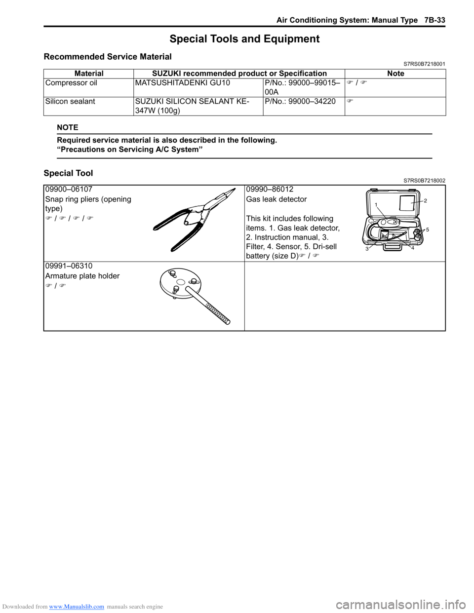
Special ToolS7RS0B7218002
Material SUZUKI recommended product or Specification Note
Compressor oil MATSUSHITADEN KI GU10 P/No.: 99000–99015–
00A �)
/ �)
Silicon sealant SUZUKI SILICON SEALANT KE-
347W (100g) P/No.: 99000–34220
�)
09900–06107 09990–86012
Snap ring pliers (opening
type) Gas leak detector
�) / �) / �) / �) This kit includes following
items. 1. Gas leak detector,
2. Instruction manual, 3.
Filter, 4. Sensor, 5. Dri-sell
battery (size D)�) / �)
09991–06310
Armature plate holder
�) / �)
1 2
3 4
5
Page 1035 of 1496
Downloaded from www.Manualslib.com manuals search engine Seat Belts: 8A-4
Front Seat Belt Removal and InstallationS7RS0B8106002
WARNING!
• Never attempt to disassemble or repair the seat belt pretensioner (retractor
assembly). If any abnormality is found, be
sure to replace it with new one as an
assembly.
• Be sure to read “Precautions on Service and Diagnosis of Seat Belt” before starting
to work and observe every precaution
during work. Ne glecting them may result in
personal injury or una ctivation of the seat
belt pretensioner when necessary.
Removal
1) Disconnect negative (–) cable at battery.
2) Disable air bag system. Refer to “Disabling Air Bag System in Section 8B”.
3) Remove center pillar lower trim.
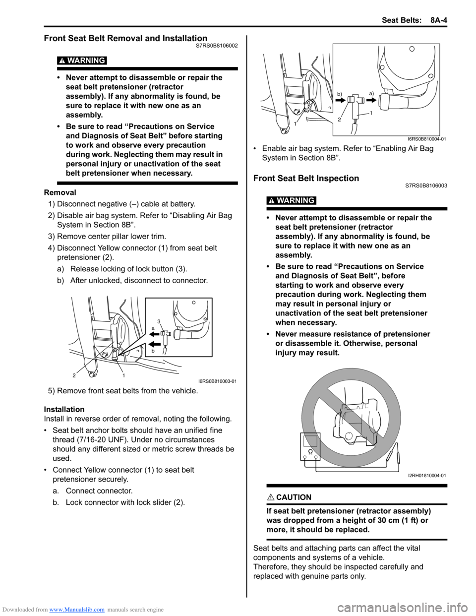
4) Disconnect Yellow connector (1) from seat belt pretensioner (2).
a) Release locking of lock button (3).
b) After unlocked, disconnect to connector.
5) Remove front seat belts from the vehicle.
Installation
Install in reverse order of removal, noting the following.
• Seat belt anchor bolts should have an unified fine thread (7/16-20 UNF). Under no circumstances
should any different sized or metric screw threads be
used.
• Connect Yellow connector (1) to seat belt pretensioner securely.
a. Connect connector.
b. Lock connector with lock slider (2). • Enable air bag system. Refer to “Enabling Air Bag
System in Section 8B”.
Front Seat Belt InspectionS7RS0B8106003
WARNING!
• Never attempt to disassemble or repair the seat belt pretensioner (retractor
assembly). If any abnormality is found, be
sure to replace it with new one as an
assembly.
• Be sure to read “Precautions on Service and Diagnosis of Seat Belt”, before
starting to work and observe every
precaution during work. Neglecting them
may result in personal injury or
unactivation of the seat belt pretensioner
when necessary.
• Never measure resistance of pretensioner or disassemble it. Otherwise, personal
injury may result.
CAUTION!
If seat belt pretensioner (retractor assembly)
was dropped from a height of 30 cm (1 ft) or
more, it should be replaced.
Seat belts and attaching parts can affect the vital
components and systems of a vehicle.
Therefore, they should be inspected carefully and
replaced with genuine parts only.
a
b
21 3I6RS0B810003-01
1
1
2
b)
a)
I6RS0B810004-01
I2RH01810004-01
Page 1038 of 1496
Downloaded from www.Manualslib.com manuals search engine 8A-7 Seat Belts:
Rear Seat Belt Removal and InstallationS7RS0B8106005
WARNING!
Be sure to read “Precautions on Service and
Diagnosis of Seat Belt” before starting to
work and observe every precaution during
work.
Removal1) Fold rear seats referring to “Folding Rear Seats” in Owners Manual.
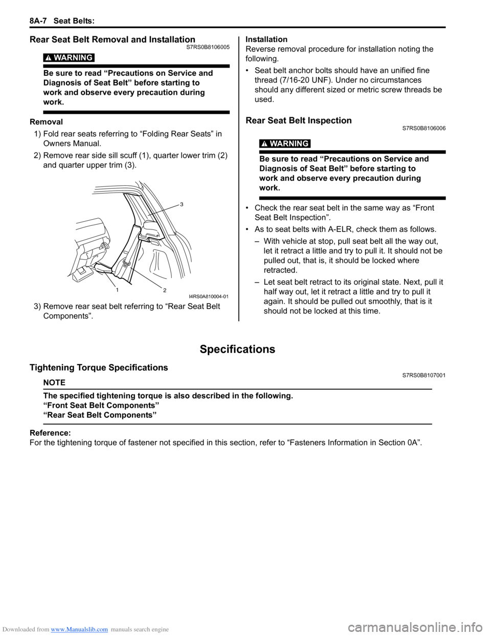
2) Remove rear side sill scuff (1), quarter lower trim (2)
and quarter upper trim (3).
3) Remove rear seat belt referring to “Rear Seat Belt Components”. Installation
Reverse removal procedure for installation noting the
following.
• Seat belt anchor bolts should have an unified fine
thread (7/16-20 UNF). Under no circumstances
should any different sized or metric screw threads be
used.Rear Seat Belt InspectionS7RS0B8106006
WARNING!
Be sure to read “Precautions on Service and
Diagnosis of Seat Belt” before starting to
work and observe every precaution during
work.
• Check the rear seat belt in the same way as “Front Seat Belt Inspection”.
• As to seat belts with A-ELR, check them as follows. – With vehicle at stop, pull seat belt all the way out, let it retract a little and try to pull it. It should not be
pulled out, that is, it should be locked where
retracted.
– Let seat belt retract to its original state. Next, pull it
half way out, let it retrac t a little and try to pull it
again. It should be pulled out smoothly, that is it
should not be locked at this time.
Specifications
Tightening Torque SpecificationsS7RS0B8107001
NOTE
The specified tightening torque is also described in the following.
“Front Seat Belt Components”
“Rear Seat Belt Components”
Reference:
For the tightening torque of fastener not specified in this section, refer to “Fasteners Information in Section 0A”.
3
2
1
I4RS0A810004-01
Page 1154 of 1496
Downloaded from www.Manualslib.com manuals search engine 8B-116 Air Bag System:
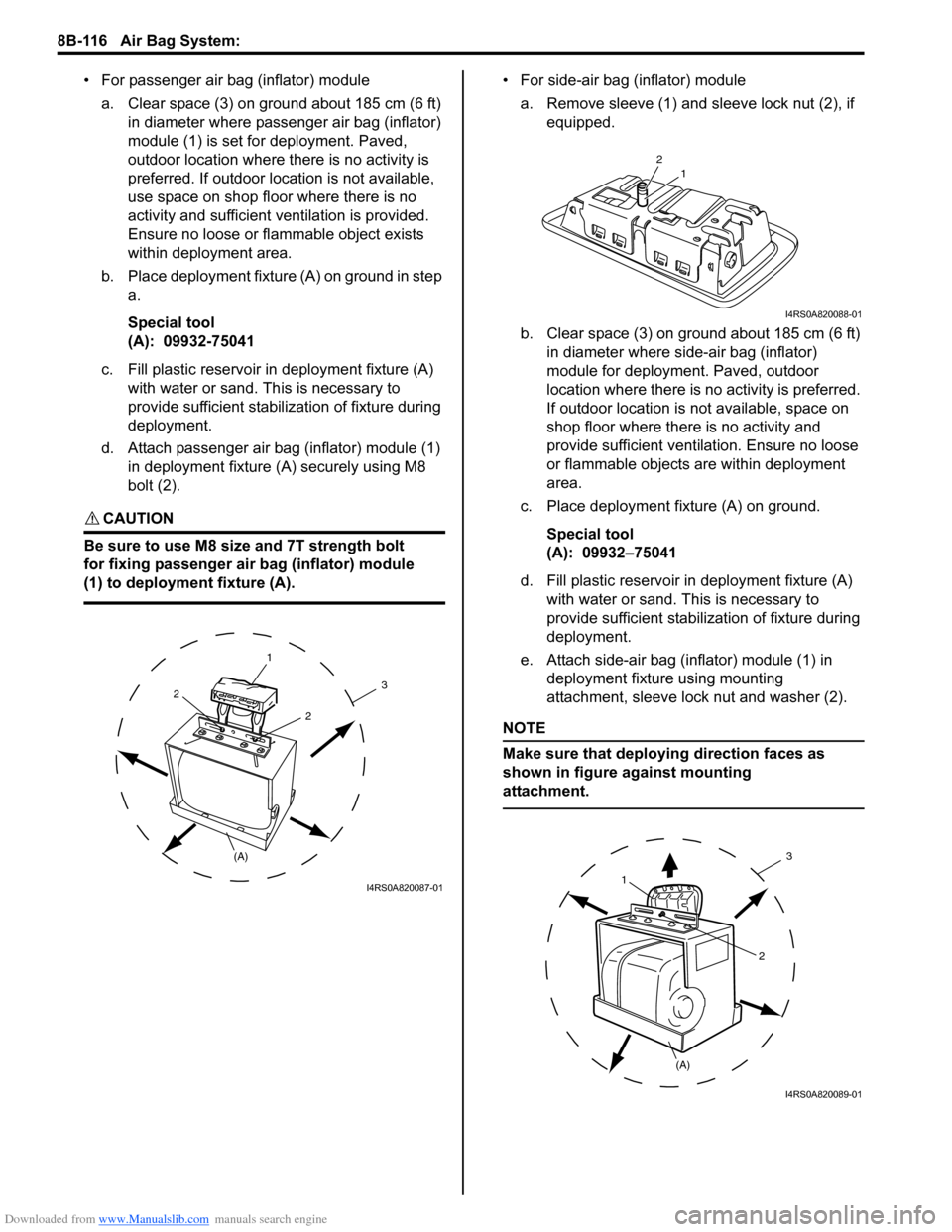
• For passenger air bag (inflator) modulea. Clear space (3) on ground about 185 cm (6 ft) in diameter where passenger air bag (inflator)
module (1) is set for deployment. Paved,
outdoor location where there is no activity is
preferred. If outdoor location is not available,
use space on shop floor where there is no
activity and sufficient ventilation is provided.
Ensure no loose or flammable object exists
within deployment area.
b. Place deployment fixture (A) on ground in step a.
Special tool
(A): 09932-75041
c. Fill plastic reservoir in deployment fixture (A) with water or sand. Th is is necessary to
provide sufficient stabilization of fixture during
deployment.
d. Attach passenger air bag (inflator) module (1) in deployment fixture (A ) securely using M8
bolt (2).
CAUTION!
Be sure to use M8 size and 7T strength bolt
for fixing passenger air bag (inflator) module
(1) to deployment fixture (A).
• For side-air bag (inflator) module
a. Remove sleeve (1) and sl eeve lock nut (2), if
equipped.
b. Clear space (3) on ground about 185 cm (6 ft) in diameter where side-air bag (inflator)
module for deployment. Paved, outdoor
location where there is no activity is preferred.
If outdoor location is not available, space on
shop floor where there is no activity and
provide sufficient ventilation. Ensure no loose
or flammable objects are within deployment
area.
c. Place deployment fixture (A) on ground.
Special tool
(A): 09932–75041
d. Fill plastic reservoir in deployment fixture (A) with water or sand. Th is is necessary to
provide sufficient stabiliz ation of fixture during
deployment.
e. Attach side-air bag (inflator) module (1) in deployment fixture using mounting
attachment, sleeve lock nut and washer (2).
NOTE
Make sure that deploying direction faces as
shown in figure against mounting
attachment.
1
(A)
2
2
3
I4RS0A820087-01
21
I4RS0A820088-01
1
(A) 2
3
I4RS0A820089-01