low SUZUKI SWIFT 2007 2.G Service Owner's Manual
[x] Cancel search | Manufacturer: SUZUKI, Model Year: 2007, Model line: SWIFT, Model: SUZUKI SWIFT 2007 2.GPages: 1496, PDF Size: 34.44 MB
Page 35 of 1496
Downloaded from www.Manualslib.com manuals search engine Maintenance and Lubrication: 0B-5
4) Screw new filter on oil filter stand by hand until the filter O-ring contacts mounting surface.
CAUTION!
To tighten oil filter prop erly, it is important to
accurately identify the position at which filter
O-ring first contacts mounting surface.
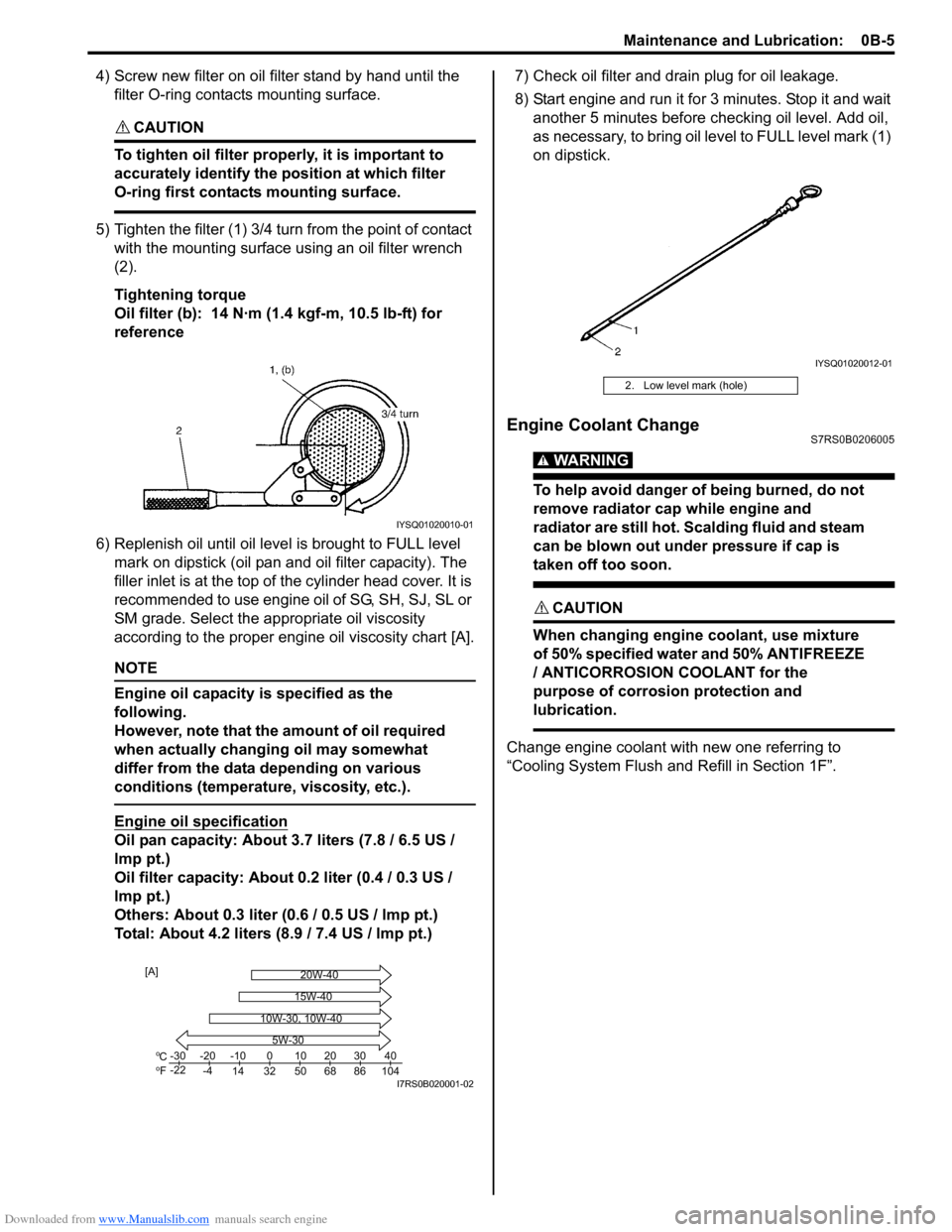
5) Tighten the filter (1) 3/4 tu rn from the point of contact
with the mounting surface using an oil filter wrench
(2).
Tightening torque
Oil filter (b): 14 N·m (1 .4 kgf-m, 10.5 lb-ft) for
reference
6) Replenish oil until oil leve l is brought to FULL level
mark on dipstick (oil pan and oil filter capacity). The
filler inlet is at the top of the cylinder head cover. It is
recommended to use engine oil of SG, SH, SJ, SL or
SM grade. Select the appropriate oil viscosity
according to the proper engine oil viscosity chart [A].
NOTE
Engine oil capacity is specified as the
following.
However, note that the amount of oil required
when actually changing oil may somewhat
differ from the data depending on various
conditions (temperature, viscosity, etc.).
Engine oil specification
Oil pan capacity: About 3.7 liters (7.8 / 6.5 US /
lmp pt.)
Oil filter capacity: About 0.2 liter (0.4 / 0.3 US /
lmp pt.)
Others: About 0.3 liter (0 .6 / 0.5 US / lmp pt.)
Total: About 4.2 liters (8.9 / 7.4 US / lmp pt.) 7) Check oil filter and drain plug for oil leakage.
8) Start engine and run it for 3 minutes. Stop it and wait
another 5 minutes before checking oil level. Add oil,
as necessary, to bring oil le vel to FULL level mark (1)
on dipstick.
Engine Coolant ChangeS7RS0B0206005
WARNING!
To help avoid danger of being burned, do not
remove radiator cap while engine and
radiator are still hot. Scalding fluid and steam
can be blown out under pressure if cap is
taken off too soon.
CAUTION!
When changing engine coolant, use mixture
of 50% specified water and 50% ANTIFREEZE
/ ANTICORROSION COOLANT for the
purpose of corrosion protection and
lubrication.
Change engine coolant with new one referring to
“Cooling System Flush and Refill in Section 1F”.
IYSQ01020010-01
Co
Fo-30
-22 -20
-4 -10
14 32 50 68 86 104 010203040
5W-30
20W-40
15W-40
10W-30, 10W-40
[A]
I7RS0B020001-02
2. Low level mark (hole)
IYSQ01020012-01
Page 36 of 1496
Downloaded from www.Manualslib.com manuals search engine 0B-6 Maintenance and Lubrication:
Exhaust System InspectionS7RS0B0206006
WARNING!
To avoid danger of being burned, do not
touch exhaust system when it is still hot.
Any service on exhaust system should be
performed when it is cool.
When carrying out periodic maintenance, or the vehicle
is raised for other service, check exhaust system as
follows:
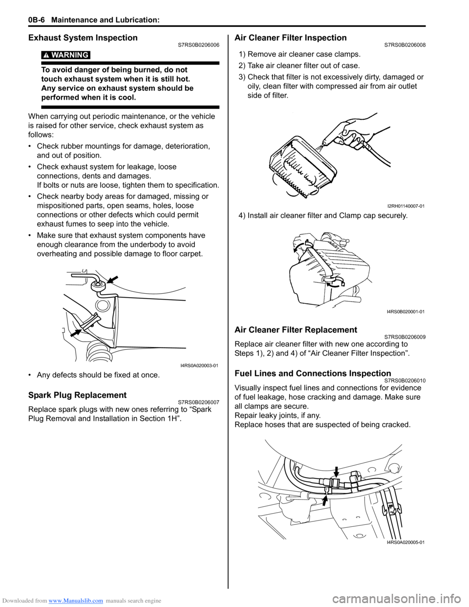
• Check rubber mountings for damage, deterioration, and out of position.
• Check exhaust system for leakage, loose connections, dents and damages.
If bolts or nuts are loose, tighten them to specification.
• Check nearby body areas for damaged, missing or mispositioned parts, ope n seams, holes, loose
connections or other defects which could permit
exhaust fumes to seep into the vehicle.
• Make sure that exhaust system components have enough clearance from the underbody to avoid
overheating and possible damage to floor carpet.
• Any defects should be fixed at once.
Spark Plug ReplacementS7RS0B0206007
Replace spark plugs with new ones referring to “Spark
Plug Removal and Installation in Section 1H”.
Air Cleaner Filter InspectionS7RS0B0206008
1) Remove air cleaner case clamps.
2) Take air cleaner filter out of case.
3) Check that filter is not excessively dirty, damaged or oily, clean filter with compressed air from air outlet
side of filter.
4) Install air cleaner filter and Clamp cap securely.
Air Cleaner Filter ReplacementS7RS0B0206009
Replace air cleaner filter with new one according to
Steps 1), 2) and 4) of “Air Cleaner Filter Inspection”.
Fuel Lines and Connections InspectionS7RS0B0206010
Visually inspect fuel lines and connections for evidence
of fuel leakage, hose cracking and damage. Make sure
all clamps are secure.
Repair leaky joints, if any.
Replace hoses that are suspected of being cracked.
I4RS0A020003-01
I2RH01140007-01
I4RS0B020001-01
I4RS0A020005-01
Page 38 of 1496
Downloaded from www.Manualslib.com manuals search engine 0B-8 Maintenance and Lubrication:
Brake Fluid InspectionS7RS0B0206035
1) Check around master cylinder and reservoir for fluid leakage. If found leaky, correct.
2) Check fluid level. If fluid level is lower than the minimum level of
reservoir, refilling is necessary. Fill reservoir with
specified brake fluid.
For the details, refer to “Brake Fluid Level Inspection
in Section 4A”.
CAUTION!
Since brake system of this vehicle is factory-
filled with brake fluid indicated on reservoir
tank cap, do not use or mix different type of
fluid when refilling; otherwise serious
damage will occur.
Do not use old or used brake fluid, or any
fluid from an unsealed container.
Brake fluid
Refer to reservoir cap of brake master cylinder.
Brake Fluid ReplacementS7RS0B0206017
Change brake fluid as follows.
Drain existing fluid from brake system completely, fill
system with specified fluid and carry out air purge
operation.
For air purging procedure, refer to“Air Bleeding of Brake
System in Section 4A”.
Brake Lever and Cable InspectionS7RS0B0206018
1) Inspect brake cable for damage and smooth movement.
Replace cable if it is in deteriorated condition. 2) Check tooth tip of each notch for damage or wear. If
any damage or wear is found, replace parking lever.
3) Check parking brake lever for proper operation and stroke, and adjust it if necessary.
For checking and adjusting procedures, refer to
“Parking Brake Inspection and Adjustment in Section
4D”.
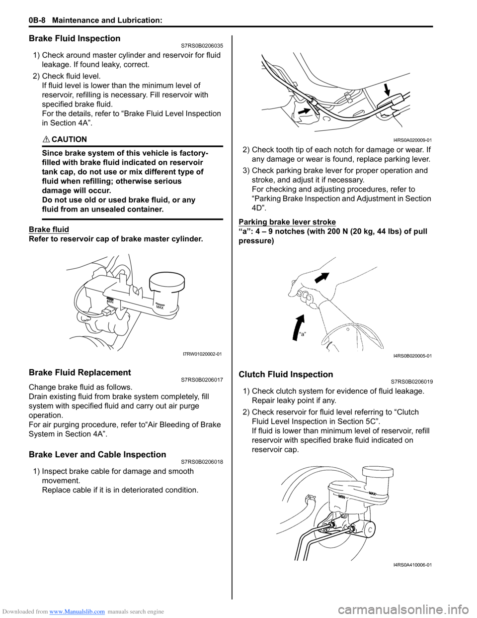
Parking brake lever stroke
“a”: 4 – 9 notches (with 200 N (20 kg, 44 lbs) of pull
pressure)
Clutch Fluid InspectionS7RS0B0206019
1) Check clutch system for evidence of fluid leakage. Repair leaky point if any.
2) Check reservoir for fluid level referring to “Clutch
Fluid Level Inspection in Section 5C”.
If fluid is lower than minimum level of reservoir, refill
reservoir with specified brake fluid indicated on
reservoir cap.
I7RW01020002-01
I4RS0A020009-01
I4RS0B020005-01
I4RS0A410006-01
Page 40 of 1496
Downloaded from www.Manualslib.com manuals search engine 0B-10 Maintenance and Lubrication:
Steering System InspectionS7RS0B0206024
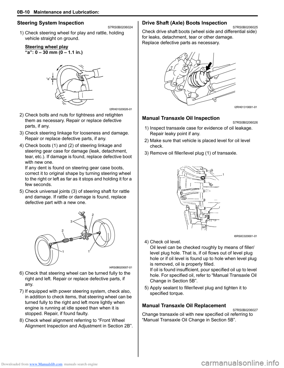
1) Check steering wheel for play and rattle, holding vehicle straight on ground.
Steering wheel play
“a”: 0 – 30 mm (0 – 1.1 in.)
2) Check bolts and nuts for tightness and retighten them as necessary. Repair or replace defective
parts, if any.
3) Check steering linkage for looseness and damage. Repair or replace defective parts, if any.
4) Check boots (1) and (2) of steering linkage and steering gear case for damage (leak, detachment,
tear, etc.). If damage is fo und, replace defective boot
with new one.
If any dent is found on steering gear case boots,
correct it to original shape by turning steering wheel
to the right or left as far as it stops and holding it for a
few seconds.
5) Check universal joints (3) of steering shaft for rattle and damage. If rattle or damage is found, replace
defective part with a new one.
6) Check that steering wheel can be turned fully to the
right and left. Repair or replace defective parts, if
any.
7) If equipped with power steering system, check also, in addition to check items, that steering wheel can be
turned fully to the right and left more lightly when
engine is running at idle speed than when it is
stopped. Repair, if found faulty.
8) Check wheel alignment referring to “Front Wheel Alignment Inspection and Adjustment in Section 2B”.
Drive Shaft (Axle) Boots InspectionS7RS0B0206025
Check drive shaft boots (wheel side and differential side)
for leaks, detachment, tear or other damage.
Replace defective parts as necessary.
Manual Transaxle Oil InspectionS7RS0B0206026
1) Inspect transaxle case for evidence of oil leakage. Repair leaky point if any.
2) Make sure that vehicle is placed level for oil level
check.
3) Remove oil filler/leve l plug (1) of transaxle.
4) Check oil level. Oil level can be checked roughly by means of filler/
level plug hole. That is, if oil flows out of level plug
hole or if oil level is found up to hole when level plug
is removed, oil is properly filled.
If oil is found insufficient, po ur specified oil up to level
hole. For specified oil, refe r to “Manual Transaxle Oil
Change in Section 5B”.
5) Apply sealant to filler/leve l plug and tighten it to
specified torque.
Manual Transaxle Oil ReplacementS7RS0B0206027
Change transaxle oil with new specified oil referring to
“Manual Transaxle Oil Change in Section 5B”.
I2RH01020026-01
2
3
2
1
1
I4RS0B020007-01
I2RH01310001-01
I6RS0C020001-01
Page 41 of 1496
Downloaded from www.Manualslib.com manuals search engine Maintenance and Lubrication: 0B-11
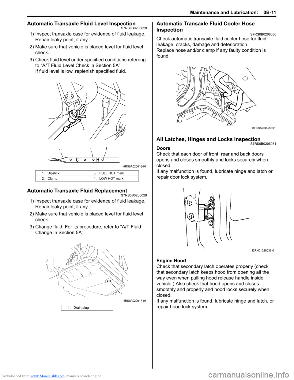
Automatic Transaxle Fluid Level InspectionS7RS0B0206028
1) Inspect transaxle case for evidence of fluid leakage.Repair leaky point, if any.
2) Make sure that vehicle is placed level for fluid level check.
3) Check fluid level under spec ified conditions referring
to “A/T Fluid Level Check in Section 5A”.
If fluid level is low, replenish specified fluid.
Automatic Transaxle Fluid ReplacementS7RS0B0206029
1) Inspect transaxle case for evidence of fluid leakage. Repair leaky point, if any.
2) Make sure that vehicle is placed level for fluid level check.
3) Change fluid. For its procedure, refer to “A/T Fluid Change in Section 5A”.
Automatic Transaxle Fluid Cooler Hose
Inspection
S7RS0B0206030
Check automatic transaxle fluid cooler hose for fluid
leakage, cracks, damage and deterioration.
Replace hose and/or clamp if any faulty condition is
found.
All Latches, Hinges and Locks InspectionS7RS0B0206031
Doors
Check that each door of front, rear and back doors
opens and closes smoothly and locks securely when
closed.
If any malfunction is found, lubricate hinge and latch or
repair door lock system.
Engine Hood
Check that secondary latch operates properly (check
that secondary latch keeps hood from opening all the
way even when pulling hood release handle inside
vehicle.) Also check that hood opens and closes
smoothly and properly and hood locks securely when
closed.
If any malfunction is found, l ubricate hinge and latch, or
repair hood lock system.
1. Dipstick 3. FULL HOT mark
2. Clamp 4. LOW HOT mark
1. Drain plug
I4RS0A020016-01
I4RS0A020017-01
I4RS0A020020-01
I2RH01020033-01
Page 42 of 1496
Downloaded from www.Manualslib.com manuals search engine 0B-12 Maintenance and Lubrication:
HVAC Air Filter (If Equipped) InspectionS7RS0B0206032
1) Remove HVAC air filter from HVAC unit referring to
“HVAC Air Filter Removal and Installation (If
Equipped) in Section 7A”.
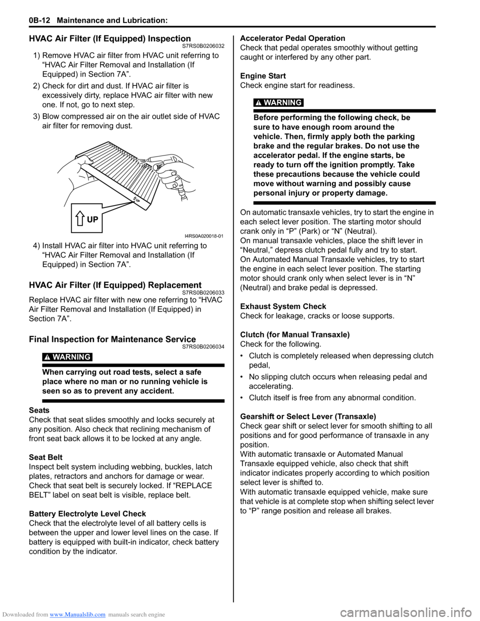
2) Check for dirt and dust. If HVAC air filter is excessively dirty, replace HVAC air filter with new
one. If not, go to next step.
3) Blow compressed air on the air outlet side of HVAC air filter for removing dust.
4) Install HVAC air filter in to HVAC unit referring to
“HVAC Air Filter Removal and Installation (If
Equipped) in Section 7A”.
HVAC Air Filter (If Equipped) ReplacementS7RS0B0206033
Replace HVAC air filter with new one referring to “HVAC
Air Filter Removal and Installation (If Equipped) in
Section 7A”.
Final Inspection for Maintenance ServiceS7RS0B0206034
WARNING!
When carrying out road tests, select a safe
place where no man or no running vehicle is
seen so as to prevent any accident.
Seats
Check that seat slides smoot hly and locks securely at
any position. Also check that reclining mechanism of
front seat back allows it to be locked at any angle.
Seat Belt
Inspect belt system including webbing, buckles, latch
plates, retractors and anchors for damage or wear.
Check that seat belt is securely locked. If “REPLACE
BELT” label on seat belt is visible, replace belt.
Battery Electrolyte Level Check
Check that the electrolyte le vel of all battery cells is
between the upper and lower level lines on the case. If
battery is equipped with built-in indicator, check battery
condition by the indicator. Accelerator Pedal Operation
Check that pedal operates
smoothly without getting
caught or interfered by any other part.
Engine Start
Check engine start for readiness.
WARNING!
Before performing th e following check, be
sure to have enough room around the
vehicle. Then, firmly apply both the parking
brake and the regular brakes. Do not use the
accelerator pedal. If the engine starts, be
ready to turn off the ignition promptly. Take
these precautions because the vehicle could
move without warning and possibly cause
personal injury or property damage.
On automatic transaxle vehicles, try to start the engine in
each select lever position. The starting motor should
crank only in “P” (Park) or “N” (Neutral).
On manual transaxle vehicles, place the shift lever in
“Neutral,” depress clutch pedal fully and try to start.
On Automated Manual Transaxl e vehicles, try to start
the engine in each select le ver position. The starting
motor should crank only when select lever is in “N”
(Neutral) and brake pedal is depressed.
Exhaust System Check
Check for leakage, cracks or loose supports.
Clutch (for Manual Transaxle)
Check for the following.
• Clutch is completely released when depressing clutch pedal,
• No slipping clutch occurs when releasing pedal and accelerating.
• Clutch itself is free fr om any abnormal condition.
Gearshift or Select Lever (Transaxle)
Check gear shift or select lever for smooth shifting to all
positions and for good performance of transaxle in any
position.
With automatic transaxle or Automated Manual
Transaxle equipped vehicle, also check that shift
indicator indicates properly according to which position
select lever is shifted to.
With automatic transaxle equipped vehicle, make sure
that vehicle is at complete stop when shifting select lever
to “P” range position and release all brakes.
I4RS0A020018-01
Page 43 of 1496
Downloaded from www.Manualslib.com manuals search engine Maintenance and Lubrication: 0B-13
Brake
Foot brake
Check the following:
• that brake pedal has proper travel,
• that brake works properly,
• that it is free from noise,
• that vehicle does not pull to one side when brake is applied.
• and that brake do not drag.
Parking brake
Check that lever has proper travel.
WARNING!
With vehicle parked on a fairly steep slope,
make sure nothing is in the way downhill to
avoid any personal injury or property
damage. Be prepared to apply regular brake
quickly even if vehicle should start to move.
Check to ensure that parking brake is fully effective
when the vehicle is stopped on the safe slope and brake
lever is pulled all the way.
Steering
• Check to ensure that steering wheel is free from instability, or abnormally heavy feeling. • Check that the vehicle does not wander or pull to one
side.
Engine
• Check that engine responds readily at all speeds.
• Check that engine is free from abnormal noise and abnormal vibration.
Body, Wheels and Power Transmitting System
Check that body, wheels and power transmitting system
are free from abnormal noise and abnormal vibration or
any other abnormal condition.
Meters and Gauge
Check that speedometer, odometer, fuel meter,
temperature gauge, etc. are operating accurately.
Lights
Check that all lights operate properly.
Windshield Defroster
Periodically check that ai r comes out from defroster
outlet when operating heater or air conditioning.
Set mode control lever to defroster position and fan
switch lever to “HI” position for this check.
Specifications
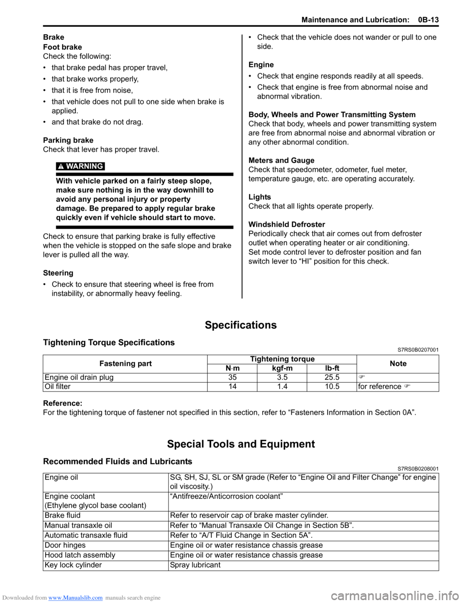
Tightening Torque SpecificationsS7RS0B0207001
Reference:
For the tightening torque of fastener not specified in this section, refer to “Fasteners Information in Section 0A”.
Special Tools and Equipment
Recommended Fluids and LubricantsS7RS0B0208001
Fastening part Tightening torque
Note
N ⋅mkgf-mlb-ft
Engine oil drain plug 35 3.5 25.5 )
Oil filter 14 1.4 10.5 for reference )
Engine oilSG, SH, SJ, SL or SM grade (Refer to “Engine Oil and Filter Change” for engine
oil viscosity.)
Engine coolant
(Ethylene glycol base coolant) “Antifreeze/Antico
rrosion coolant”
Brake fluid Refer to reservoir cap of brake master cylinder.
Manual transaxle oil Refer to “Manual Transaxle Oil Change in Section 5B”.
Automatic transaxle fluid Refer to “A/T Fluid Change in Section 5A”.
Door hinges Engine oil or water resistance chassis grease
Hood latch assembly Engine oil or water resistance chassis grease
Key lock cylinder Spray lubricant
Page 45 of 1496
Downloaded from www.Manualslib.com manuals search engine Table of Contents 1- i
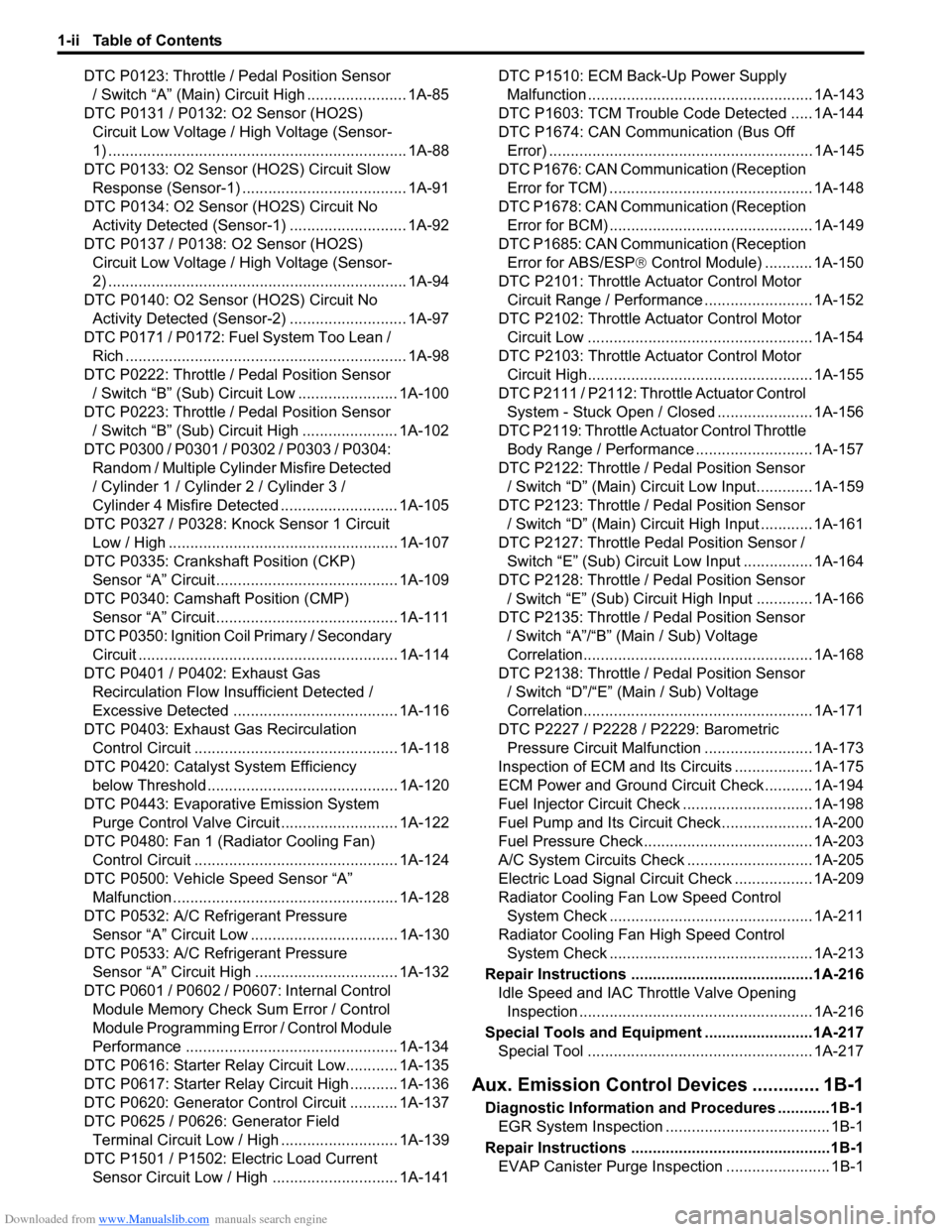
1
Section 1
CONTENTS
Engine
Precautions ................................................. 1-1
Precautions............................................................. 1-1
Precautions for Engine .......................................... 1-1
Engine General Information and
Diagnosis ............. .................................... 1A-1
Precautions........................................................... 1A-1
Precautions on Engine Service ........................... 1A-1
Precaution on On-Board Diagnostic (OBD) System .............................................................. 1A-1
Precautions in Diagnosing Trouble ..................... 1A-1
Precautions of ECM Circuit Inspection................ 1A-2
Precautions of Electric Throttle Body System
Calibration ......................................................... 1A-2
General Description ............................................. 1A-2 Statement on Cleanliness and Care ................... 1A-2
Engine Diagnosis General Description ............... 1A-3
On-Board Diagnostic System Description ........... 1A-3
Data Link Connector (DLC) ................................. 1A-6
Engine and Emission Control System Description ........................................................ 1A-6
CAN Communication System Description........... 1A-7
Air Intake System Description ............................. 1A-9
Description of Electric Throttle Body System ...... 1A-9
Description of Electric Throttle Body System Calibration ....................................................... 1A-10
Fuel Cut Control Description ............................. 1A-10
Generator Control System Description ............. 1A-11
Electronic Control System Description .............. 1A-12
Engine and Emission Control Input / Output Table ............................................................... 1A-18
Schematic and Routing Diagram ...................... 1A-19 Engine and Emission Control System Diagram .......................................................... 1A-19
Component Locatio n ......................................... 1A-21
Electronic Control System Components Location .......................................................... 1A-21
Diagnostic Information and Procedures .......... 1A-22 Engine and Emission Control System Check.... 1A-22
Malfunction Indicator Lamp (MIL) Check .......... 1A-25
DTC Check ....................................................... 1A-26
DTC Clearance ................................................. 1A-27
DTC Table ......................................................... 1A-27
Fail-Safe Table ................ .................................. 1A-31 Scan Tool Data ................................................. 1A-33
Visual Inspection ............................................... 1A-37
Engine Basic Inspection .................................... 1A-38
Engine Symptom Diagnosis .............................. 1A-41
MIL Does Not Come ON with Ignition Switch
ON and Engine Stop (but Engine Can Be
Started) ........................................................... 1A-47
Malfunction Indicator Lamp Remains ON after Engine Starts................................................... 1A-48
DTC P0010: “A” Camshaft Position Actuator Circuit .............................................................. 1A-49
DTC P0011 / P0012: “A” Camshaft Position - Timing Over-Advanced or System
Performance / -Retarded................................. 1A-52
DTC P0031 / P0032: HO2S Heater Control Circuit Low / High (Sensor-1) .......................... 1A-54
DTC P0037 / P0038: HO2S Heater Control Circuit Low / High (Sensor-2) .......................... 1A-56
DTC P0101: Mass or Volume Air Flow Circuit Range / Performance ...................................... 1A-58
DTC P0102: Mass or Volume Air Flow Circuit Low Input......................................................... 1A-61
DTC P0103: Mass or Volume Air Flow Circuit High Input ........................................................ 1A-63
DTC P0106: Manifold Absolute Pressure /
Barometric Pressure Circuit Range /
Performance.................................................... 1A-64
DTC P0107: Manifold Absolute Pressure /
Barometric Pressure Circ uit Low Input............ 1A-66
DTC P0108: Manifold Absolute Pressure /
Barometric Pressure Circ uit High Input ........... 1A-67
DTC P0111: Intake Air Temperature Sensor 1 Circuit Range / Performance ........................... 1A-69
DTC P0112: Intake Air Temperature Sensor 1 Circuit Low ...................................................... 1A-72
DTC P0113: Intake Air Temperature 1 Sensor Circuit High...................................................... 1A-74
DTC P0116: Engine Coolant Temperature Circuit Range / Performance ........................... 1A-76
DTC P0117: Engine Coolant Temperature Circuit Low ...................................................... 1A-79
DTC P0118: Engine Coolant Temperature Circuit High...................................................... 1A-81
DTC P0122: Throttle / Pedal Position Sensor / Switch “A” (Main) Circuit Low ........................ 1A-83
Page 46 of 1496
Downloaded from www.Manualslib.com manuals search engine 1-ii Table of Contents
DTC P0123: Throttle / Pedal Position Sensor / Switch “A” (Main) Circuit High ....................... 1A-85
DTC P0131 / P0132: O2 Sensor (HO2S) Circuit Low Voltage / High Voltage (Sensor-
1) ..................................................................... 1A-88
DTC P0133: O2 Sensor (HO2S) Circuit Slow
Response (Sensor- 1) ...................................... 1A-91
DTC P0134: O2 Sensor (HO2S) Circuit No Activity Detected (Sensor -1) ........................... 1A-92
DTC P0137 / P0138: O2 Sensor (HO2S) Circuit Low Voltage / High Voltage (Sensor-
2) ..................................................................... 1A-94
DTC P0140: O2 Sensor (HO2S) Circuit No Activity Detected (Sensor -2) ........................... 1A-97
DTC P0171 / P0172: Fuel System Too Lean / Rich ................................................................. 1A-98
DTC P0222: Throttle / Pedal Position Sensor / Switch “B” (Sub) Circuit Low ....................... 1A-100
DTC P0223: Throttle / Pedal Position Sensor / Switch “B” (Sub) Circuit High ...................... 1A-102
DTC P0300 / P0301 / P0302 / P0303 / P0304: Random / Multiple Cylin der Misfire Detected
/ Cylinder 1 / Cylinder 2 / Cylinder 3 /
Cylinder 4 Misfire Detected ........................... 1A-105
DTC P0327 / P0328: Knoc k Sensor 1 Circuit
Low / High ..................................................... 1A-107
DTC P0335: Crankshaft Position (CKP) Sensor “A” Circuit .......................................... 1A-109
DTC P0340: Camshaft Position (CMP) Sensor “A” Circuit .......................................... 1A-111
DTC P0350: Ignition Coil Primary / Secondary Circuit ............................................................ 1A-114
DTC P0401 / P0402: Exhaust Gas Recirculation Flow Insufficient Detected /
Excessive Detected ...................................... 1A-116
DTC P0403: Exhaust Gas Recirculation Control Circuit ................... ............................ 1A-118
DTC P0420: Catalyst System Efficiency
below Threshold ................ ............................ 1A-120
DTC P0443: Evaporativ e Emission System
Purge Control Valve Circuit ........................... 1A-122
DTC P0480: Fan 1 (Radiator Cooling Fan) Control Circuit ................... ............................ 1A-124
DTC P0500: Vehicle Speed Sensor “A” Malfunction .................................................... 1A-128
DTC P0532: A/C Refrigerant Pressure Sensor “A” Circuit Low ... ............................... 1A-130
DTC P0533: A/C Refrigerant Pressure Sensor “A” Circuit High ................................. 1A-132
DTC P0601 / P0602 / P0607: Internal Control Module Memory Check Sum Error / Control
Module Programming Error / Control Module
Performance ................................................. 1A-134
DTC P0616: Starter Relay Circuit Low............ 1A-135
DTC P0617: Starter Relay Circuit High ........... 1A-136
DTC P0620: Generator Control Circuit ........... 1A-137
DTC P0625 / P0626: Generator Field Terminal Circuit Low / High . .......................... 1A-139
DTC P1501 / P1502: Electric Load Current Sensor Circuit Low / High . ............................ 1A-141 DTC P1510: ECM Back-Up Power Supply
Malfunction .................................................... 1A-143
DTC P1603: TCM Trouble Code Detected ..... 1A-144
DTC P1674: CAN Communication (Bus Off Error) ............................................................. 1A-145
DTC P1676: CAN Communication (Reception Error for TCM) ............................................... 1A-148
DTC P1678: CAN Communication (Reception Error for BCM) ............................................... 1A-149
DTC P1685: CAN Communication (Reception Error for ABS/ESP ® Control Module) ........... 1A-150
DTC P2101: Throttle Actuator Control Motor Circuit Range / Performance ......................... 1A-152
DTC P2102: Throttle Actuator Control Motor Circuit Low .................................................... 1A-154
DTC P2103: Throttle Actuator Control Motor Circuit High.................................................... 1A-155
DTC P2111 / P2112: Throttle Actuator Control System - Stuck Open / Closed ...................... 1A-156
DTC P2119: Throttle Actu ator Control Throttle
Body Range / Performance ........................... 1A-157
DTC P2122: Throttle / Pedal Position Sensor / Switch “D” (Main) Circuit Low Input............. 1A-159
DTC P2123: Throttle / Pedal Position Sensor / Switch “D” (Main) Circuit High Input ............ 1A-161
DTC P2127: Throttle Pedal Position Sensor / Switch “E” (Sub) Circuit Low Input ................ 1A-164
DTC P2128: Throttle / Pedal Position Sensor
/ Switc
h “E” (Sub) Circuit High Input ............. 1A-166
DTC P2135: Throttle / Pedal Position Sensor / Switch “A”/“B” (Main / Sub) Voltage
Correlation..................................................... 1A-168
DTC P2138: Throttle / Pedal Position Sensor / Switch “D”/“E” (Main / Sub) Voltage
Correlation..................................................... 1A-171
DTC P2227 / P2228 / P2229: Barometric Pressure Circuit Malfunction ......................... 1A-173
Inspection of ECM and Its Circuits .................. 1A-175
ECM Power and Ground Circuit Check........... 1A-194
Fuel Injector Circuit Check .............................. 1A-198
Fuel Pump and Its Circuit Check..................... 1A-200
Fuel Pressure Check....................................... 1A-203
A/C System Circuits Check ............................. 1A-205
Electric Load Signal Circuit Check .................. 1A-209
Radiator Cooling Fan Low Speed Control System Check ............................................... 1A-211
Radiator Cooling Fan High Speed Control System Check ............................................... 1A-213
Repair Instructions ......... .................................1A-216
Idle Speed and IAC Throttle Valve Opening Inspection ...................................................... 1A-216
Special Tools and Equipmen t .........................1A-217
Special Tool .................................................... 1A-217
Aux. Emission Control Devices ............. 1B-1
Diagnostic Information and Procedures ............1B-1
EGR System Inspection ...................................... 1B-1
Repair Instructions ............ ..................................1B-1
EVAP Canister Purge Inspec tion ........................ 1B-1
Page 51 of 1496
Downloaded from www.Manualslib.com manuals search engine Engine General Information and Diagnosis: 1A-1
Engine
Engine General Information and Diagnosis
Precautions
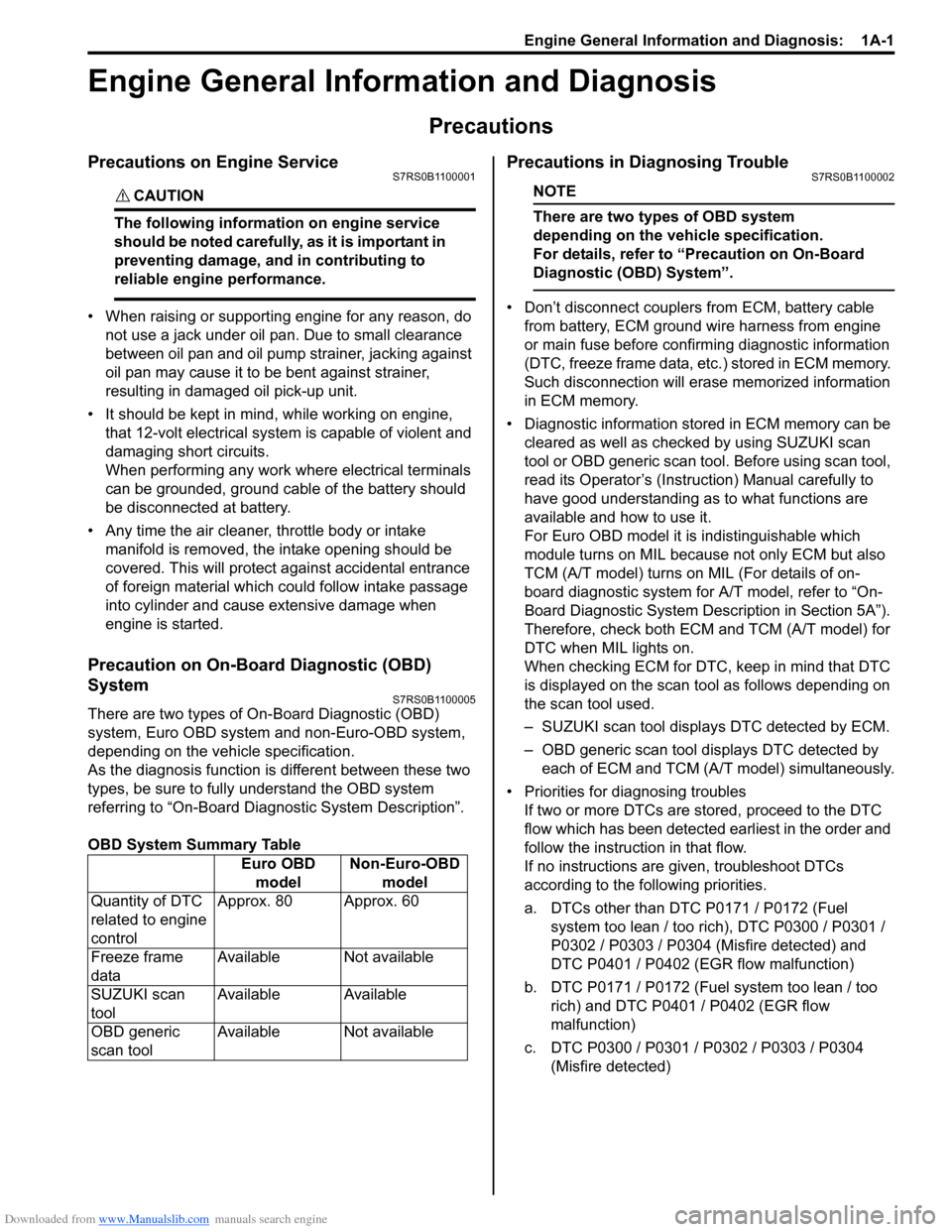
Precautions on Engine ServiceS7RS0B1100001
CAUTION!
The following information on engine service
should be noted carefully, as it is important in
preventing damage, and in contributing to
reliable engine performance.
• When raising or supporting engine for any reason, do
not use a jack under oil pan. Due to small clearance
between oil pan and oil pump strainer, jacking against
oil pan may cause it to be bent against strainer,
resulting in damaged oil pick-up unit.
• It should be kept in mind , while working on engine,
that 12-volt electrical syste m is capable of violent and
damaging short circuits.
When performing any work where electrical terminals
can be grounded, ground cable of the battery should
be disconnected at battery.
• Any time the air cleaner, throttle body or intake manifold is removed, the intake opening should be
covered. This will protect against accidental entrance
of foreign material which could follow intake passage
into cylinder and cause extensive damage when
engine is started.
Precaution on On-Board Diagnostic (OBD)
System
S7RS0B1100005
There are two types of On -Board Diagnostic (OBD)
system, Euro OBD system and non-Euro-OBD system,
depending on the vehicle specification.
As the diagnosis function is different between these two
types, be sure to fully understand the OBD system
referring to “On-Board Diagnostic System Description”.
OBD System Summary Table
Precautions in Diagnosing TroubleS7RS0B1100002
NOTE
There are two types of OBD system
depending on the vehicle specification.
For details, refer to “Precaution on On-Board
Diagnostic (OBD) System”.
• Don’t disconnect couplers from ECM, battery cable
from battery, ECM ground wire harness from engine
or main fuse before confirming diagnostic information
(DTC, freeze frame data, etc.) stored in ECM memory.
Such disconnection will erase memorized information
in ECM memory.
• Diagnostic information stored in ECM memory can be cleared as well as checke d by using SUZUKI scan
tool or OBD generic scan tool. Before using scan tool,
read its Operator’s (Instruction) Manual carefully to
have good understanding as to what functions are
available and how to use it.
For Euro OBD model it is indistinguishable which
module turns on MIL because not only ECM but also
TCM (A/T model) turns on MIL (For details of on-
board diagnostic system for A/T model, refer to “On-
Board Diagnostic System Description in Section 5A”).
Therefore, check both ECM and TCM (A/T model) for
DTC when MIL lights on.
When checking ECM for DTC, keep in mind that DTC
is displayed on the scan tool as follows depending on
the scan tool used.
– SUZUKI scan tool displays DTC detected by ECM.
– OBD generic scan tool displays DTC detected by each of ECM and TCM (A/T model) simultaneously.
• Priorities for diagnosing troubles If two or more DTCs are stored, proceed to the DTC
flow which has been detected earliest in the order and
follow the instructi on in that flow.
If no instructions are given, troubleshoot DTCs
according to the following priorities.
a. DTCs other than DTC P0171 / P0172 (Fuel system too lean / too rich), DTC P0300 / P0301 /
P0302 / P0303 / P0304 (Misfire detected) and
DTC P0401 / P0402 (EGR flow malfunction)
b. DTC P0171 / P0172 (Fuel system too lean / too rich) and DTC P0401 / P0402 (EGR flow
malfunction)
c. DTC P0300 / P0301 / P0302 / P0303 / P0304 (Misfire detected)
Euro OBD
model Non-Euro-OBD
model
Quantity of DTC
related to engine
control Approx. 80 Approx. 60
Freeze frame
data Available Not available
SUZUKI scan
tool Available Available
OBD generic
scan tool Available Not available