spark SUZUKI SWIFT 2007 2.G Service Owner's Manual
[x] Cancel search | Manufacturer: SUZUKI, Model Year: 2007, Model line: SWIFT, Model: SUZUKI SWIFT 2007 2.GPages: 1496, PDF Size: 34.44 MB
Page 393 of 1496
Downloaded from www.Manualslib.com manuals search engine Ignition System: 1H-1
Engine
Ignition System
General Description
Ignition System ConstructionS7RS0B1801001
The ignition system is an electronic (distributorless) ignition system. It consists of the parts as described below.
• ECM
It detects the engine and vehicle conditions through the si gnals from the sensors, determines the most suitable
ignition timing and time for electricity to flow to the primar y coil and sends a signal to the ignitor (power unit) in the
ignition coil assembly.
• Ignition coil assembly (including an ignitor)
The ignition coil assembly has a built -in ignitor which turns ON and OFF the current flow to the primary coil
according to the signal from ECM. When the current flow to the primary coil is turned OFF, a high voltage is induced
in the secondary coil.
• High-tension cords and spark plugs
• CMP sensor (Camshaft position sensor) and CKP sensor (Crankshaft position sensor)
Using signals from these sensors, ECM identifies the specific cylinder whose piston is in the compression stroke,
detects the crank angle and adjusts in itial ignition timing automatically.
• TP sensor, ECT sensor, MAP sensor, MAF sensor, IAT sensor, knock sensor and other sensors / switches
Although this ignition system does not have a distributor, it has two ignition coil assemblies (one is for No.1 and No.4
spark plugs and the other is for No.2 and No.3 spark plugs). W hen an ignition signal is sent from ECM to the ignitor in
the ignition coil assembly for No.1 and No.4 spark plugs, a high voltage is induced in the secondary coil and that
passes through the high-tension cords and causes No.1 and No.4 spark plugs to spark simultaneously. Likewise,
when an ignition signal is sent to the ignitor in the ot her ignition coil assembly, No.2 and No.3 spark plugs spark
simultaneously.
Page 394 of 1496
Downloaded from www.Manualslib.com manuals search engine 1H-2 Ignition System:
Schematic and Routing Diagram
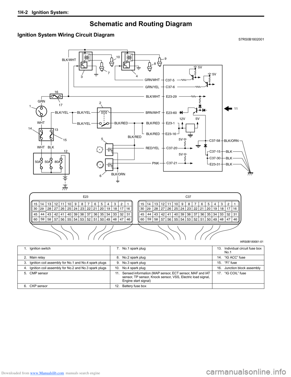
Ignition System Wiring Circuit DiagramS7RS0B1802001
E23-60
E23-29 12V 5V
5V
E23-1
E23-16
BLK/WHT
BLK/RED
BLK/RED BLK/RED
BLK/YELBLK/YEL
BLK/YEL
GRN
BLKWHT
WHT
BRN/WHT
BLK/ORN
BLK
BLK
C37-20
BLK/RED
PNK
5V
C37-21
BLK/WHT
7
3 4
1
12 5
6
2
11
8
9
10
GRN/YEL
GRN/WHT
C37-6
C37-5 5V
5V
RED/YEL
C37-58
C37-15
C37-30
E23
C37
34
1819
567
1011
17
20
47 46
495051
2122
52 16
25 9
24
14
29
55
57 54 53
59
60 58 2
262728
15
30
56 4832 31
34353637
40
42 39 38
44
45 43 41 331
1213
238
34
1819
567
1011
17
20
47 46
495051
2122
52 16
25 9
24
14
29
55
57 54 53
59
60 58 2
262728
15
30
56 4832 31
34353637
40
42 39 38
44
45 43 41 331
1213
238
13
14
15
16
17
50A50A80A
BLK/ORN
E23-31 BLK
I4RS0B180001-01
1. Ignition switch 7. No.1 spark plug 13. Individual circuit fuse box
No.1
2. Main relay 8. No.2 spark plug 14. “IG ACC” fuse
3. Ignition coil assembly for No.1 and No.4 spark plugs 9. No.3 spark plug 15. “FI” fuse
4. Ignition coil assembly for No.2 and No.3 spark plugs 10. No.4 spark plug 16. Junction block assembly
5. CMP sensor 11. Sensed information (MAP sensor, ECT sensor, MAF and IAT
sensor, TP sensor, Knock sensor, VSS, Electric load signal,
Engine start signal) 17. “IG COIL” fuse
6. CKP sensor 12. Battery fuse box
Page 395 of 1496
Downloaded from www.Manualslib.com manuals search engine Ignition System: 1H-3
Component Location
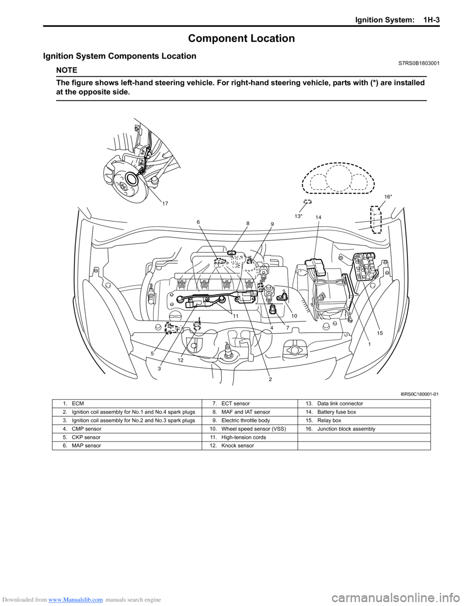
Ignition System Components LocationS7RS0B1803001
NOTE
The figure shows left-hand steering vehicle. For right-hand steering vehicle, parts with (*) are installed
at the opposite side.
16*
1
2
14
7
5 12 11
410
6
89
3 13*
15
17
I6RS0C180001-01
1. ECM 7. ECT sensor13. Data link connector
2. Ignition coil assembly for No.1 and No.4 spark plugs 8. MAF and IAT sensor 14. Battery fuse box
3. Ignition coil assembly for No.2 and No.3 spark plugs 9. Electric throttle body 15. Relay box
4. CMP sensor 10. Wheel speed sensor (VSS) 16. Junction block assembly
5. CKP sensor 11. High-tension cords
6. MAP sensor 12. Knock sensor
Page 396 of 1496
Downloaded from www.Manualslib.com manuals search engine 1H-4 Ignition System:
Diagnostic Information and Procedures
Ignition System Symptom DiagnosisS7RS0B1804001
Reference Waveform of Ignition SystemS7RS0B1804002
Refer to “Reference waveform No.5”, “Reference waveform No.6” and “Reference waveform No.7” under “Inspection
of ECM and Its Circuits in Section 1A” for waveform of Ignition trigger signal.
Ignition System CheckS7RS0B1804003
Condition Possible cause Correction / Reference Item
Engine cranks, but will
not start or hard to start
(No spark) Blown fuse for ignition coil
Replace.
Loose connection or disconnection of
lead wire or high-tension cord(s) Connect securely.
Faulty high-tension cord(s) Replace.
Faulty spark plug(s) Replace.
Faulty ignition coil Replace ignition coil assembly.
Faulty CKP sensor or CKP sensor plate Clean, tighten or replace.
Faulty CMP sensor or sensor rotor tooth
of camshaft Clean, tighten or replace.
Faulty ECM Replace.
Poor fuel economy or
engine performance Incorrect ignition timing
Check related sensors and CKP sensor plate.
Faulty spark plug(s) or high-tension
cord(s) Adjust, clean or replace.
Faulty ignition coil assembly Replace.
Faulty CKP sensor or CKP sensor plate Clean, tighten or replace.
Faulty CMP sensor or sensor rotor tooth
of camshaft Clean, tighten or replace.
Faulty knock sensor Replace.
Faulty ECM Replace.
StepAction YesNo
1 Was “Engine and Emission Control System Check”
performed? Go to Step 2.
Go to “Engine and
Emission Control
System Check in
Section 1A”.
2 Ignition spark test
1) Check all spark plugs for condition and type referring to
“Spark Plug Inspection”.
2) If OK, perform ignition spark test referring to “Ignition Spar k Tes t”.
Is spark emitted from all spark plugs? Go to Step 13. Go to Step 3.
3 DTC check
1) Perform DTC check referring to “DTC Check in Section
1A”.
Is DTC stored in ECM? Go to applicable DTC
diag. flow.
Go to Step 4.
4 Electrical connection check
1) Check ignition coil assemblies and high-tension cords
for electrical connection.
Are they connected securely? Go to Step 5.
Connect securely.
5 High-tension cords check
1) Check high-tension cord for resistance referring to
“High-Tension Cord Inspection”.
Is check result satisfactory? Go to Step 6.
Replace high-tension
cord(s).
Page 398 of 1496
Downloaded from www.Manualslib.com manuals search engine 1H-6 Ignition System:
Ignition Spark TestS7RS0B1804004
1) Remove air cleaner assembly with air intake pipe.
2) Disconnect all injector couplers from injectors.
WARNING!
Without disconnection of injector couplers,
combustible gas may come out from spark
plug holes during this test and may get
ignited in engine room.
3) Remove spark plug and check it for condition and
type referring to “Spark Plug Inspection”.
4) If OK, connect ignition coil coupler to ignition coil assembly and connect spark plug to ignition coil
assembly or high-tension cord. Ground spark plug. 5) Crank engine and check if each spark plug sparks.
6) If no spark is emitted, inspect the related parts as
described in “Ignition System Symptom Diagnosis”.
Repair Instructions
High-Tension Cord Removal and InstallationS7RS0B1806001
Removal
1) Remove air cleaner assembly with air intake pipe and cylinder head upper cover.
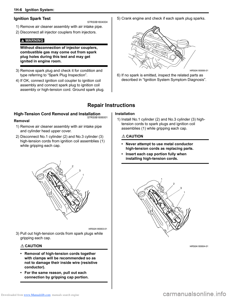
2) Disconnect No.1 cylinder (2) and No.3 cylinder (3)
high-tension cords from ignition coil assemblies (1)
while gripping each cap.
3) Pull out high-tension cords from spark plugs while gripping each cap.
CAUTION!
• Removal of high-tension cords together with clamps will be recommended so as
not to damage their inside wire (resistive
conductor).
• For the same reason, pull out each connection by gripping cap portion.
Installation
1) Install No.1 cylinder (2) and No.3 cylinder (3) high-
tension cords to spark plugs and ignition coil
assemblies (1) while gripping each cap.
CAUTION!
• Never attempt to use metal conductor high-tension cords as replacing parts.
• Insert each cap portion fully when installing high-tension cords.
I4RS0A180006-01
I4RS0A180003-01
I4RS0A180004-01
Page 399 of 1496
Downloaded from www.Manualslib.com manuals search engine Ignition System: 1H-7
High-Tension Cord InspectionS7RS0B1806002
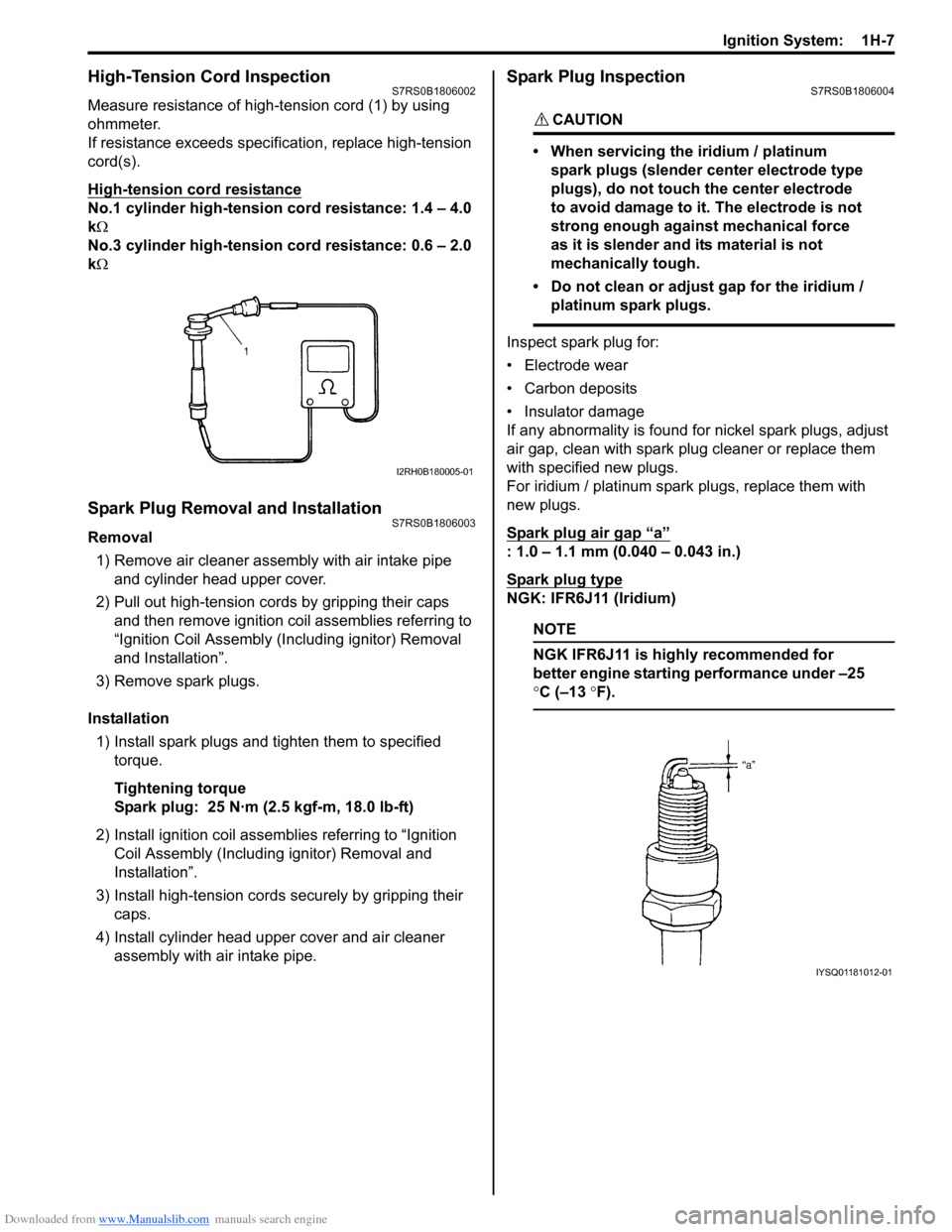
Measure resistance of high-tension cord (1) by using
ohmmeter.
If resistance exceeds specification, replace high-tension
cord(s).
High-tension cord resistance
No.1 cylinder high-tension cord resistance: 1.4 – 4.0
k Ω
No.3 cylinder high-tension cord resistance: 0.6 – 2.0
k Ω
Spark Plug Removal and InstallationS7RS0B1806003
Removal
1) Remove air cleaner assembly with air intake pipe and cylinder head upper cover.
2) Pull out high-tension cords by gripping their caps and then remove ignition coil assemblies referring to
“Ignition Coil Assembly (Inc luding ignitor) Removal
and Installation”.
3) Remove spark plugs.
Installation 1) Install spark plugs and tighten them to specified torque.
Tightening torque
Spark plug: 25 N·m (2.5 kgf-m, 18.0 lb-ft)
2) Install ignition coil assemblies referring to “Ignition Coil Assembly (Including ignitor) Removal and
Installation”.
3) Install high-tension cords securely by gripping their caps.
4) Install cylinder head upper cover and air cleaner assembly with air intake pipe.
Spark Plug InspectionS7RS0B1806004
CAUTION!
• When servicing the iridium / platinum
spark plugs (slender center electrode type
plugs), do not touch the center electrode
to avoid damage to it. The electrode is not
strong enough against mechanical force
as it is slender and its material is not
mechanically tough.
• Do not clean or adjust gap for the iridium / platinum spark plugs.
Inspect spark plug for:
• Electrode wear
• Carbon deposits
• Insulator damage
If any abnormality is found for nickel spark plugs, adjust
air gap, clean with spark plug cleaner or replace them
with specified new plugs.
For iridium / platinum spark plugs, replace them with
new plugs.
Spark plug air gap
“a”
: 1.0 – 1.1 mm (0.040 – 0.043 in.)
Spark plug type
NGK: IFR6J11 (Iridium)
NOTE
NGK IFR6J11 is highly recommended for
better engine starting performance under –25
°C (–13 °F).
I2RH0B180005-01
IYSQ01181012-01
Page 400 of 1496

Downloaded from www.Manualslib.com manuals search engine 1H-8 Ignition System:
Ignition Coil Assembly (Including ignitor)
Removal and Installation
S7RS0B1806005
Removal1) Disconnect negative (–) cable at battery.
2) Remove air cleaner assembly with air intake pipe and cylinder head upper cover.
3) Disconnect ignition coil coupler.
4) Disconnect high-tension cord (3) from ignition coil assembly (2).
5) Remove ignition coil bolts (1) and then pull out ignition coil assembly.
Installation 1) Install ignition coil assembly (2).
2) Tighten ignition coil bolts (1) to specified torque, and then connect igni tion coil coupler.
Tightening torque
Ignition coil bolt (a): 10 N·m (1.0 kgf-m, 7.5 lb-ft)
3) Install high-tension cord (3) to ignition coil assembly while gripping its cap.
4) Install cylinder head upper cover and air cleaner assembly with air intake pipe.
5) Connect negative (–) cable to battery.
Ignition Coil Assembly (Including ignitor)
Inspection
S7RS0B1806006
Measure secondary coil for resistance.
If resistance is out of specification, replace ignition coil
assembly.
Secondary coil resistance
7.5 – 10.3 k Ω at 20 °C, 68 ° F
Ignition Timing InspectionS7RS0B1806007
NOTE
• Ignition timing is not adjustable. If ignition
timing is out of specification, check
system related parts.
• Before starting engine, place transmission gear shift lever in “Neutral” (shift selector
lever to “P” range for A/T model), and set
parking brake.
1) Connect scan tool to DLC (1) with ignition switch OFF.
Special tool
(A): SUZUKI scan tool
2) Start engine and warm it up to normal operating temperature.
3) Make sure that all of electrical loads except ignition are switched off.
4) Check to be sure that idle speed is within specification referring to “Idle Speed and IAC
Throttle Valve Opening Inspection in Section 1A”
5) Fix ignition timing by using “Fixed Spark” of “Misc Test” mode on scan tool.
I2RH0B180006-01
I3RM0A180004-01
I2RH0B180007-01
(A)
1
I4RS0B180003-01
Page 401 of 1496
Downloaded from www.Manualslib.com manuals search engine Ignition System: 1H-9
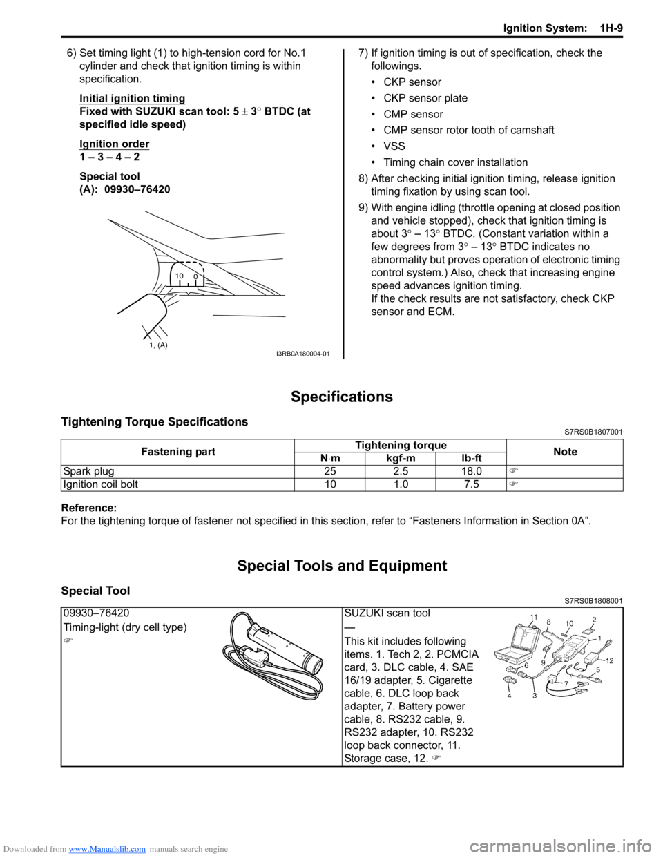
6) Set timing light (1) to high-tension cord for No.1 cylinder and check that ignition timing is within
specification.
Initial ignition timing
Fixed with SUZUKI scan tool: 5 ± 3° BTDC (at
specified idle speed)
Ignition order
1 – 3 – 4 – 2
Special tool
(A): 09930–76420 7) If ignition timing is out
of specification, check the
followings.
• CKP sensor
• CKP sensor plate
• CMP sensor
• CMP sensor rotor tooth of camshaft
• VSS
• Timing chain cover installation
8) After checking initial igniti on timing, release ignition
timing fixation by using scan tool.
9) With engine idling (throttl e opening at closed position
and vehicle stopped), check that ignition timing is
about 3 ° – 13° BTDC. (Constant variation within a
few degrees from 3 ° – 13° BTDC indicates no
abnormality but proves operation of electronic timing
control system.) Also, check that increasing engine
speed advances ignition timing.
If the check results are not satisfactory, check CKP
sensor and ECM.
Specifications
Tightening Torque SpecificationsS7RS0B1807001
Reference:
For the tightening torque of fastener not specified in this section, refer to “Fasteners Information in Section 0A”.
Special Tools and Equipment
Special ToolS7RS0B1808001
1, (A)10
0I3RB0A180004-01
Fastening part Tightening torque
Note
N ⋅mkgf-mlb-ft
Spark plug 25 2.5 18.0 �)
Ignition coil bolt 10 1.0 7.5 �)
09930–76420SUZUKI scan tool
Timing-light (dry cell type) —
�) This kit includes following
items. 1. Tech 2, 2. PCMCIA
card, 3. DLC cable, 4. SAE
16/19 adapter, 5. Cigarette
cable, 6. DLC loop back
adapter, 7. Battery power
cable, 8. RS232 cable, 9.
RS232 adapter, 10. RS232
loop back connector, 11.
Storage case, 12. �)
Page 416 of 1496
Downloaded from www.Manualslib.com manuals search engine 1J-6 Charging System:
Generator Test (Overcharged Battery Check)S7RS0B1A04004
1) To determine battery condition, refer to “Battery Description”.
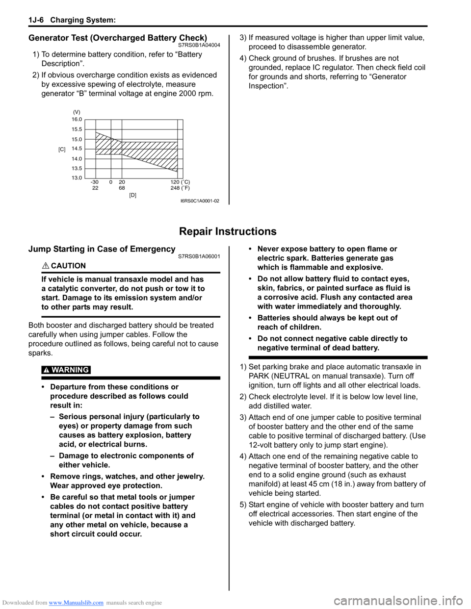
2) If obvious overcharge condition exists as evidenced by excessive spewing of electrolyte, measure
generator “B” terminal voltage at engine 2000 rpm. 3) If measured voltage is higher than upper limit value,
proceed to disassemble generator.
4) Check ground of brushes. If brushes are not grounded, replace IC regulator. Then check field coil
for grounds and shorts, referring to “Generator
Inspection”.
Repair Instructions
Jump Starting in Case of EmergencyS7RS0B1A06001
CAUTION!
If vehicle is manual transaxle model and has
a catalytic converter, do not push or tow it to
start. Damage to its emission system and/or
to other parts may result.
Both booster and discharged battery should be treated
carefully when using ju mper cables. Follow the
procedure outlined as follows, being careful not to cause
sparks.
WARNING!
• Departure from these conditions or procedure described as follows could
result in:
– Serious personal injury (particularly to eyes) or property damage from such
causes as battery explosion, battery
acid, or electrical burns.
– Damage to electronic components of either vehicle.
• Remove rings, watches, and other jewelry. Wear approved eye protection.
• Be careful so that metal tools or jumper cables do not contact positive battery
terminal (or metal in contact with it) and
any other metal on vehicle, because a
short circuit could occur. • Never expose battery to open flame or
electric spark. Batteries generate gas
which is flammable and explosive.
• Do not allow battery fluid to contact eyes, skin, fabrics, or painted surface as fluid is
a corrosive acid. Flush any contacted area
with water immediately and thoroughly.
• Batteries should always be kept out of reach of children.
• Do not connect negative cable directly to negative terminal of dead battery.
1) Set parking brake and place automatic transaxle in PARK (NEUTRAL on manual transaxle). Turn off
ignition, turn off lights and all other electrical loads.
2) Check electrolyte level. If it is below low level line, add distilled water.
3) Attach end of one jumper cable to positive terminal of booster battery and the other end of the same
cable to positive terminal of discharged battery. (Use
12-volt battery only to jump start engine).
4) Attach one end of the remaining negative cable to negative terminal of booster battery, and the other
end to a solid engine ground (such as exhaust
manifold) at least 45 cm (18 in.) away from battery of
vehicle being started.
5) Start engine of vehicle with booster battery and turn off electrical accessories. Then start engine of the
vehicle with discharged battery.
16.0
15.5
15.0
14.5
14.0
13.5
13.0 -30 0 20
[C]
[D]
68
22120 (˚C)
248 (˚F)
(V)
I6RS0C1A0001-02
Page 417 of 1496
Downloaded from www.Manualslib.com manuals search engine Charging System: 1J-7
With Charging Equipment
CAUTION!
When jump starting engine with charging
equipment, be sure equipment used is 12-
volt and negative ground. Do not use 24-volt
charging equipment. Using such equipment
can cause serious damage to electrical
system or electronic parts.
Battery Dismounting and RemountingS7RS0B1A06002
WARNING!
When handling battery, following safety
precautions should be followed:
• Hydrogen gas is produced by battery. A flame or spark near battery may cause the
gas to ignite.
• Battery fluid is highly acidic. Avoid spilling on clothing or other fabric. Any spilled
electrolyte should be flushed with large
quantity of water and cleaned immediately.
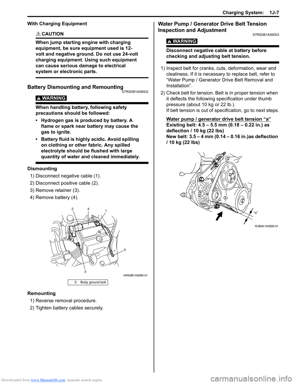
Dismounting
1) Disconnect negative cable (1).
2) Disconnect positive cable (2).
3) Remove retainer (3).
4) Remove battery (4).
Remounting 1) Reverse removal procedure.
2) Tighten battery cables securely.
Water Pump / Generator Drive Belt Tension
Inspection and Adjustment
S7RS0B1A06003
WARNING!
Disconnect negative cable at battery before
checking and adjusting belt tension.
1) Inspect belt for cranks, cuts, deformation, wear and clealiness. If it is necessary to replace belt, refer to
“Water Pump / Generator Drive Belt Removal and
Installation”.
2) Check belt for tension. Belt is in proper tension when it deflects the following specification under thumb
pressure (about 10 kg or 22 lb.).
If belt tension is out of spec ification, go to next steps.
Water pump / generator drive belt tension
“a”
Existing belt: 4.5 – 5.5 mm (0.18 – 0.22 in.) as
deflection / 10 kg (22 lbs)
New belt: 3.5 – 4 mm (0.14 – 0.16 in.)as deflection
/ 10 kg (22 lbs)
5. Body ground bolt
1
3 5
2
4
I4RS0B1A0006-01
“a”
I5JB0A1A0008-01