low SUZUKI SWIFT 2007 2.G Service Workshop Manual
[x] Cancel search | Manufacturer: SUZUKI, Model Year: 2007, Model line: SWIFT, Model: SUZUKI SWIFT 2007 2.GPages: 1496, PDF Size: 34.44 MB
Page 435 of 1496
Downloaded from www.Manualslib.com manuals search engine Front Suspension: 2B-2
Front Wheel Alignment ConstructionS7RS0B2201002
Among factors for front wheel alignment, only toe setting
can be adjusted. Camber and caster are not adjustable.
Therefore, should camber or caster be out of
specification due to the damage caused by hazardous
road conditions or collision, whether the damage is in
body or in suspension should be determined and
damaged body should be repaired or damaged
suspension should be replaced.
Preliminary Checks Prior to Adjustment Front Wheel
Alignment
Steering and vibration complaints are not always the
result of improper wheel alignment. An additional item to
be checked is the possibility of tire lead due to worn or
improperly manufactured tires. “Lead” is the vehicle
deviation from a straight path on a level road without
hand pressure on the steering wheel. Refer to “Radial
Tire Lead / Pull Description in Section 2D” in order to
determine if the vehicle has a tire lead problem. Before
making any adjustment affecting wheel alignment, the
following checks and inspections should be made to
ensure correctness of alignment readings and alignment
adjustments:
• Check all tires for proper inflation pressures and approximately the same tread wear. • Check for loose of ball join
ts. Check tie-rod ends; if
excessive looseness is noted, it must be corrected
before adjusting.
• Check for run-out of wheels and tires.
• Check vehicle trim heights; if it is out of limit and a
correction is needed, it must be done before adjusting
toe.
• Check for loose of suspension control arms.
• Check for loose or missin g stabilizer bar attachments.
• Consideration must be given to excess loads, such as
tool boxes. If this excess load is normally carried in
vehicle, it should remain in vehicle during alignment
checks.
• Consider condition of equipment being used to check alignment and follow manufa cturer’s instructions.
• Regardless of equipment used to check alignment, vehicle must be placed on a level surface.
NOTE
To prevent possible incorrect reading of toe,
camber or caster, vehicle front and rear end
must be moved up and down a few times
before inspection.
Repair Instructions
Front Wheel Alignment Inspection and
Adjustment
S7RS0B2206001
Toe Inspection and Adjustment
Preparation for toe inspection and adjustment.
• Place vehicle in unloaded state on level surface.
• Set steering wheel in straight state.
• Check that inflation pressure of each tire is adjusted properly and wheel is free from deflection.
• Check that each suspension part is free from bend, dent, wear or damage in any other form.
• Check that ground clearance at the right and left is just about the same.
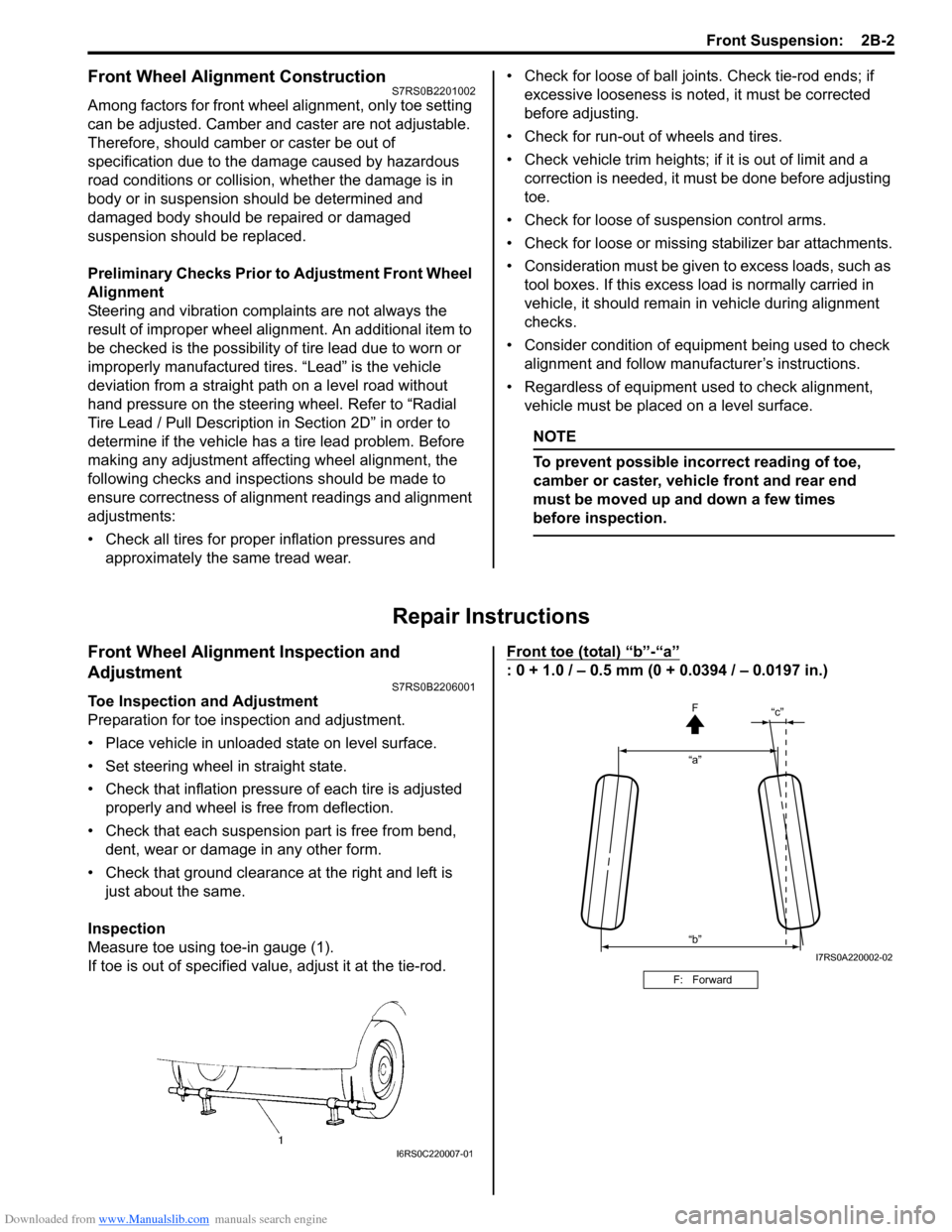
Inspection
Measure toe using toe-in gauge (1).
If toe is out of specified value, adjust it at the tie-rod. Front toe (total) “b”-“a”
: 0 + 1.0 / – 0.5 mm (0 + 0.0394 / – 0.0197 in.)
I6RS0C220007-01
F: Forward
“a”
“c”
“b” F
I7RS0A220002-02
Page 436 of 1496
Downloaded from www.Manualslib.com manuals search engine 2B-3 Front Suspension:
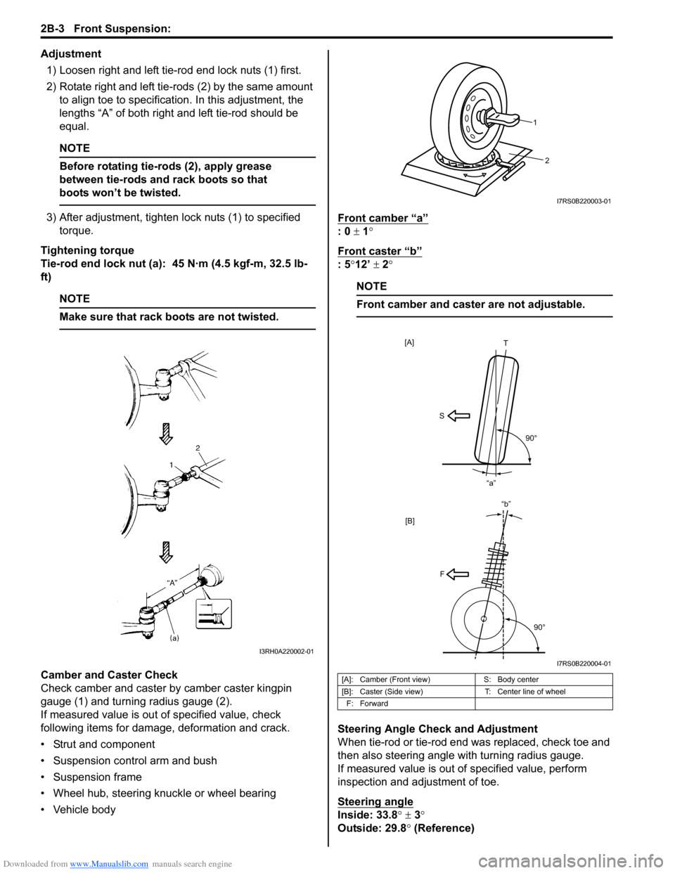
Adjustment1) Loosen right and left tie-rod end lock nuts (1) first.
2) Rotate right and left tie-rods (2) by the same amount to align toe to specification. In this adjustment, the
lengths “A” of both right and left tie-rod should be
equal.
NOTE
Before rotating tie-rods (2), apply grease
between tie-rods and rack boots so that
boots won’t be twisted.
3) After adjustment, tighten lock nuts (1) to specified torque.
Tightening torque
Tie-rod end lock nut (a): 45 N·m (4.5 kgf-m, 32.5 lb-
ft)
NOTE
Make sure that rack boots are not twisted.
Camber and Caster Check
Check camber and caster by camber caster kingpin
gauge (1) and turning radius gauge (2).
If measured value is out of specified value, check
following items for damage, deformation and crack.
• Strut and component
• Suspension control arm and bush
• Suspension frame
• Wheel hub, steering knuckle or wheel bearing
• Vehicle body Front camber “a”
: 0
± 1°
Front caster “b”
: 5 °12’ ± 2°
NOTE
Front camber and caster are not adjustable.
Steering Angle Check and Adjustment
When tie-rod or tie-rod end was replaced, check toe and
then also steering angle with turning radius gauge.
If measured value is out of specified value, perform
inspection and adjustment of toe.
Steering angle
Inside: 33.8 ° ± 3 °
Outside: 29.8 ° (Reference)
I3RH0A220002-01
[A]: Camber (Front view) S: Body center
[B]: Caster (Side view) T: Center line of wheel
F: Forward
2
1
I7RS0B220003-01
[B]
S T
90°
“a”
[A]
F
90°
“b”
I7RS0B220004-01
Page 437 of 1496
Downloaded from www.Manualslib.com manuals search engine Front Suspension: 2B-4
Reference Information
Side slip
When checked with side slip tester, side slip should
satisfy following specification.Side slip
0 to IN 3.0 mm/m (0 to IN 0.118 in/3.3 ft)
If side slip is greatly di
fferent, toe or front wheel
alignment may not be correct.
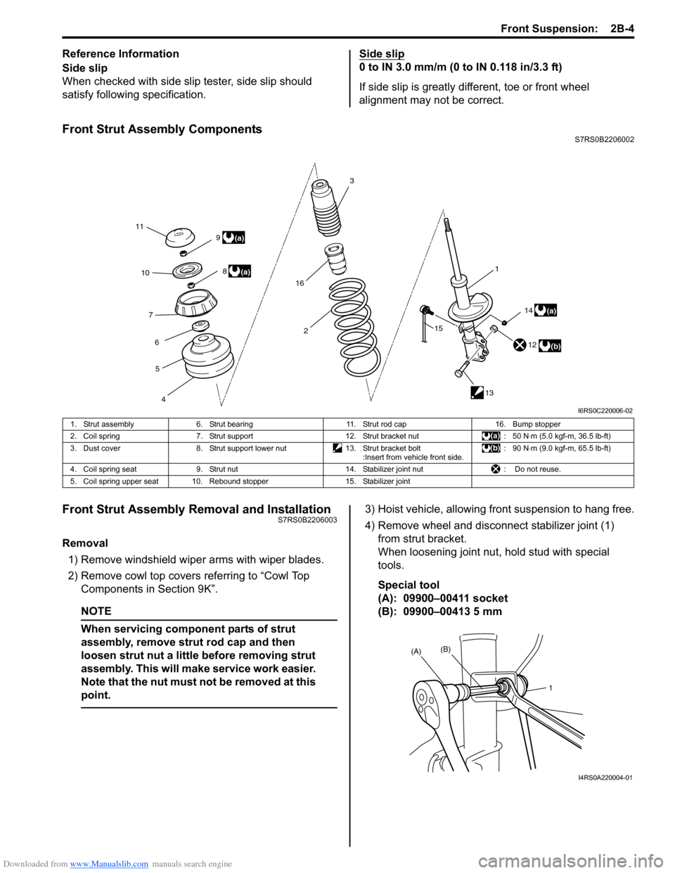
Front Strut Assembly ComponentsS7RS0B2206002
Front Strut Assembly Removal and InstallationS7RS0B2206003
Removal
1) Remove windshield wipe r arms with wiper blades.
2) Remove cowl top covers referring to “Cowl Top
Components in Section 9K”.
NOTE
When servicing component parts of strut
assembly, remove stru t rod cap and then
loosen strut nut a little before removing strut
assembly. This will make service work easier.
Note that the nut must not be removed at this
point.
3) Hoist vehicle, allowing front suspension to hang free.
4) Remove wheel and disconn ect stabilizer joint (1)
from strut bracket.
When loosening joint nu t, hold stud with special
tools.
Special tool
(A): 09900–00411 socket
(B): 09900–00413 5 mm
11 3
2 1
12
13
4
5
6
7
10
8(a)
(b)
9
(a)
14
15(a)
16
I6RS0C220006-02
1. Strut assembly
6. Strut bearing 11. Strut rod cap16. Bump stopper
2. Coil spring 7. Strut support 12. Strut bracket nut : 50 N⋅m (5.0 kgf-m, 36.5 lb-ft)
3. Dust cover 8. Strut support lower nut 13. Strut bracket bolt
:Insert from vehicle front side. : 90 N
⋅m (9.0 kgf-m, 65.5 lb-ft)
4. Coil spring seat 9. Strut nut 14. Stabilizer joint nut : Do not reuse.
5. Coil spring upper seat 10. Rebound stopper 15. Stabilizer joint
1
(A)
(B)
I4RS0A220004-01
Page 438 of 1496
Downloaded from www.Manualslib.com manuals search engine 2B-5 Front Suspension:
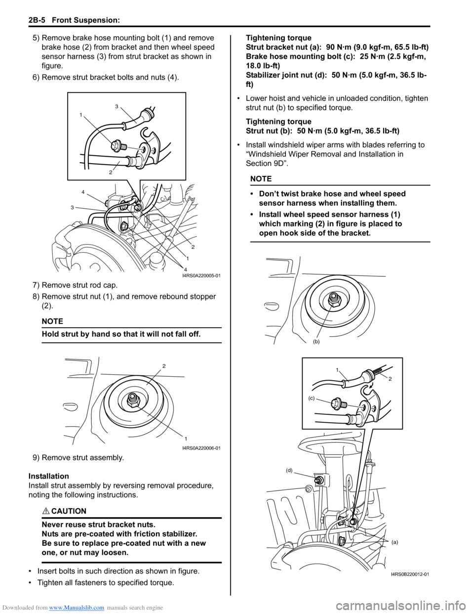
5) Remove brake hose mounting bolt (1) and remove brake hose (2) from bracket and then wheel speed
sensor harness (3) from strut bracket as shown in
figure.
6) Remove strut bracket bolts and nuts (4).
7) Remove strut rod cap.
8) Remove strut nut (1), and remove rebound stopper (2).
NOTE
Hold strut by hand so th at it will not fall off.
9) Remove strut assembly.
Installation
Install strut assembly by reversing removal procedure,
noting the following instructions.
CAUTION!
Never reuse strut bracket nuts.
Nuts are pre-coated with friction stabilizer.
Be sure to replace pre-coated nut with a new
one, or nut may loosen.
• Insert bolts in such direction as shown in figure.
• Tighten all fasteners to specified torque. Tightening torque
Strut bracket nut (a): 90 N·m (9.0 kgf-m, 65.5 lb-ft)
Brake hose mounting bolt (c): 25 N·m (2.5 kgf-m,
18.0 lb-ft)
Stabilizer joint nut (d): 50 N·m (5.0 kgf-m, 36.5 lb-
ft)
• Lower hoist and vehicle in unloaded condition, tighten strut nut (b) to specified torque.
Tightening torque
Strut nut (b): 50 N·m (5.0 kgf-m, 36.5 lb-ft)
• Install windshield wiper arms with blades referring to
“Windshield Wiper Removal and Installation in
Section 9D”.
NOTE
• Don’t twist brake hose and wheel speed sensor harness when installing them.
• Install wheel speed sensor harness (1) which marking (2) in figure is placed to
open hook side of the bracket.
1 3
2
2
1
4
4
3
I4RS0A220005-01
2
1
I4RS0A220006-01
(d) (a)
(b)
(c)
1
2
I4RS0B220012-01
Page 439 of 1496
Downloaded from www.Manualslib.com manuals search engine Front Suspension: 2B-6
• Tighten wheel nuts to specified torque.
Tightening torque
Wheel nut: 85 N·m (8.5 kgf-m, 61.5 lb-ft)
• After installation, confirm front wheel alignment.
Front Strut Assembly Disassembly and
Assembly
S7RS0B2206004
WARNING!
Use a regular coil spring compressor and
follow the operation procedure described in
the Instruction Manual.
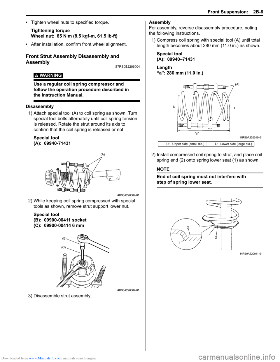
Disassembly 1) Attach special tool (A) to coil spring as shown. Turn special tool bolts alternat ely until coil spring tension
is released. Rotate the strut around its axis to
confirm that the coil spring is released or not.
Special tool
(A): 09940-71431
2) While keeping coil spring compressed with special
tools as shown, remove strut support lower nut.
Special tool
(B): 09900-00411 socket
(C): 09900-00414 6 mm
3) Disassemble strut assembly. Assembly
For assembly, reverse disassembly procedure, noting
the following instructions.
1) Compress coil spring with special tool (A) until total
length becomes about 280 mm (11.0 in.) as shown.
Special tool
(A): 09940–71431
Length
“a”: 280 mm (11.0 in.)
2) Install compressed coil spring to strut, and place coil
spring end (2) onto spring lower seat (1) as shown.
NOTE
End of coil spring must not interfere with
step of spring lower seat.
I4RS0A220009-01
(B)
(C)
I4RS0A220007-01
U: Upper side (small dia.) L: Lower side (large dia.)
I4RS0A220010-01
I4RS0A220011-01
Page 440 of 1496
Downloaded from www.Manualslib.com manuals search engine 2B-7 Front Suspension:
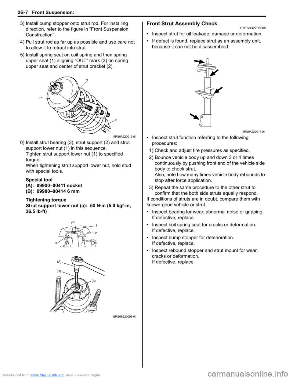
3) Install bump stopper onto strut rod. For installing
direction, refer to the figure in “Front Suspension
Construction”.
4) Pull strut rod as far up as possible and use care not to allow it to re tract into strut.
5) Install spring seat on coil spring and then spring upper seat (1) aligning “OUT” mark (3) on spring
upper seat and center of strut bracket (2).
6) Install strut bearing (3), strut support (2) and strut
support lower nut (1) in this sequence.
Tighten strut support lower nut (1) to specified
torque.
When tightening strut support lower nut, hold stud
with special tools.
Special tool
(A): 09900–00411 socket
(B): 09900–00414 6 mm
Tightening torque
Strut support lower nut (a): 50 N·m (5.0 kgf-m,
36.5 lb-ft)Front Strut Assembly CheckS7RS0B2206005
• Inspect strut for oil leakage, damage or deformation.
• If defect is found, replace strut as an assembly unit, because it can not be disassembled.
• Inspect strut function re ferring to the following
procedures:
1) Check and adjust tire pressures as specified.
2) Bounce vehicle body up and down 3 or 4 times continuously by pushing front end of the vehicle side
body to check strut.
Also, note how many times vehicle body rebounds to
stop after force application.
3) Repeat the same procedure to the other strut to confirm that the both side struts equally respond.
If conditions of struts are in doubt, compare them with
known-good vehicle or strut.
• Inspect bearing for wear, abnormal noise or gripping. If defective, replace.
• Inspect coil spring seat for cracks or deformation.
If defective, replace.
• Inspect bump stopper for deterioration. If defective, replace.
• Inspect rebound stopper and strut mount for wear, cracks or deformation.
If defective, replace.
I4RS0A220012-01
I6RS0B220006-01
I4RS0A220014-01
Page 442 of 1496
Downloaded from www.Manualslib.com manuals search engine 2B-9 Front Suspension:
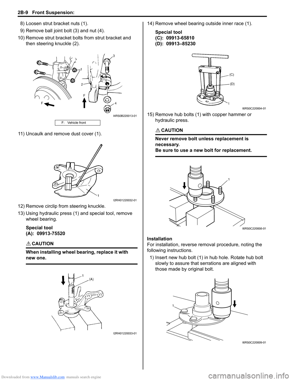
8) Loosen strut bracket nuts (1).
9) Remove ball joint bolt (3) and nut (4).
10) Remove strut bracket bolt s from strut bracket and
then steering knuckle (2).
11) Uncaulk and remove dust cover (1).
12) Remove circlip from steering knuckle.
13) Using hydraulic press (1) and special tool, remove wheel bearing.
Special tool
(A): 09913-75520
CAUTION!
When installing wheel bearing, replace it with
new one.
14) Remove wheel bearing outside inner race (1).
Special tool
(C): 09913-65810
(D): 09913–85230
15) Remove hub bolts (1) with copper hammer or hydraulic press.
CAUTION!
Never remove bolt unle ss replacement is
necessary.
Be sure to use a new bolt for replacement.
Installation
For installation, reverse removal procedure, noting the
following instructions.
1) Insert new hub bolt (1) in hub hole. Rotate hub bolt slowly to assure that serrations are aligned with
those made by original bolt.
F: Vehicle front
I4RS0B220013-01
I2RH01220032-01
I2RH01220033-01
I6RS0C220004-01
1
I6RS0C220008-01
1
I6RS0C220009-01
Page 446 of 1496
Downloaded from www.Manualslib.com manuals search engine 2B-13 Front Suspension:
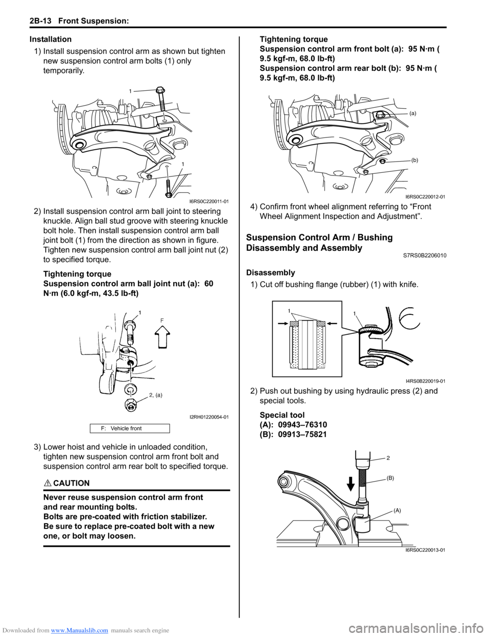
Installation1) Install suspension control arm as shown but tighten new suspension contro l arm bolts (1) only
temporarily.
2) Install suspensi on control arm ball joint to steering
knuckle. Align ball stud gr oove with steering knuckle
bolt hole. Then install su spension control arm ball
joint bolt (1) from the direction as shown in figure.
Tighten new suspension cont rol arm ball joint nut (2)
to specified torque.
Tightening torque
Suspension control arm ball joint nut (a): 60
N·m (6.0 kgf-m, 43.5 lb-ft)
3) Lower hoist and vehicle in unloaded condition, tighten new suspension control arm front bolt and
suspension control arm rear bolt to specified torque.
CAUTION!
Never reuse suspension control arm front
and rear mounting bolts.
Bolts are pre-coated with friction stabilizer.
Be sure to replace pre-coated bolt with a new
one, or bolt may loosen.
Tightening torque
Suspension control arm front bolt (a): 95 N·m (
9.5 kgf-m, 68.0 lb-ft)
Suspension control arm re ar bolt (b): 95 N·m (
9.5 kgf-m, 68.0 lb-ft)
4) Confirm front wheel alignment referring to “Front Wheel Alignment Inspection and Adjustment”.
Suspension Control Arm / Bushing
Disassembly and Assembly
S7RS0B2206010
Disassembly
1) Cut off bushing flange (rubber) (1) with knife.
2) Push out bushing by using hydraulic press (2) and special tools.
Special tool
(A): 09943–76310
(B): 09913–75821
F: Vehicle front
1
1
I6RS0C220011-01
I2RH01220054-01
(a)(b)
I6RS0C220012-01
I4RS0B220019-01
2
(A)
(B)
I6RS0C220013-01
Page 448 of 1496
Downloaded from www.Manualslib.com manuals search engine 2B-15 Front Suspension:
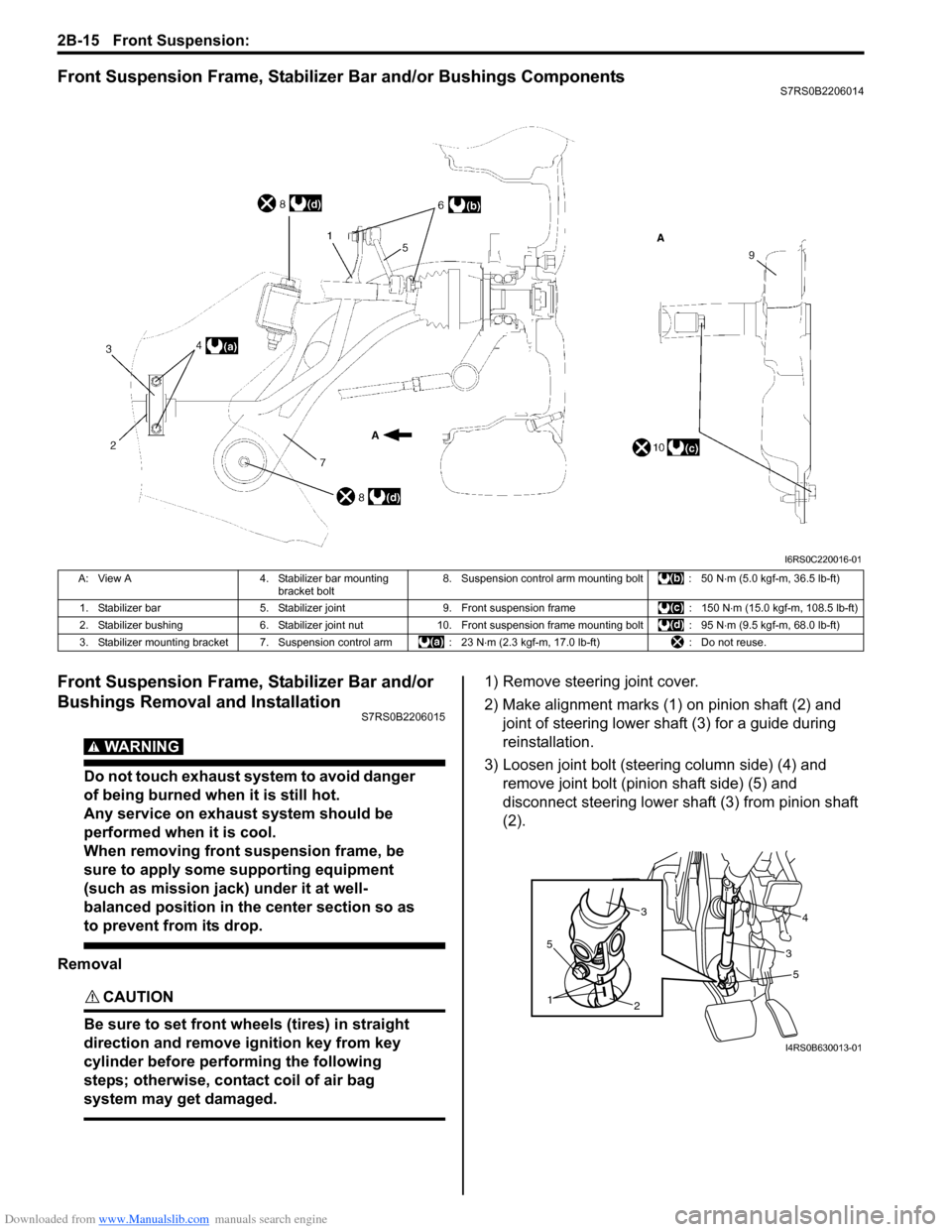
Front Suspension Frame, Stabilizer Bar and/or Bushings ComponentsS7RS0B2206014
Front Suspension Frame, Stabilizer Bar and/or
Bushings Removal and Installation
S7RS0B2206015
WARNING!
Do not touch exhaust system to avoid danger
of being burned when it is still hot.
Any service on exhaust system should be
performed when it is cool.
When removing front suspension frame, be
sure to apply some supporting equipment
(such as mission jack) under it at well-
balanced position in the center section so as
to prevent from its drop.
Removal
CAUTION!
Be sure to set front wheels (tires) in straight
direction and remove ignition key from key
cylinder before performing the following
steps; otherwise, contact coil of air bag
system may get damaged.
1) Remove steering joint cover.
2) Make alignment marks (1) on pinion shaft (2) and joint of steering lower shaft (3) for a guide during
reinstallation.
3) Loosen joint bolt (steering column side) (4) and remove joint bolt (pin ion shaft side) (5) and
disconnect steering lower shaft (3) from pinion shaft
(2).
I6RS0C220016-01
A: View A 4. Stabilizer bar mounting
bracket bolt 8. Suspension control arm mounting bolt : 50 N
⋅m (5.0 kgf-m, 36.5 lb-ft)
1. Stabilizer bar 5. Stabilizer joint 9. Front suspension frame : 150 N⋅m (15.0 kgf-m, 108.5 lb-ft)
2. Stabilizer bushing 6. Stabilizer joint nut10. Front suspension frame mounting bolt : 95 N ⋅m (9.5 kgf-m, 68.0 lb-ft)
3. Stabilizer mounting bracket 7. Suspension control arm : 23 N⋅m (2.3 kgf-m, 17.0 lb-ft) : Do not reuse.
5
2
1
5
34
3
I4RS0B630013-01
Page 449 of 1496
Downloaded from www.Manualslib.com manuals search engine Front Suspension: 2B-16
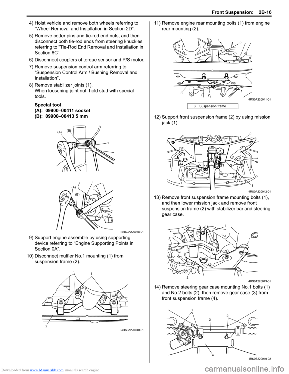
4) Hoist vehicle and remove both wheels referring to “Wheel Removal and Installation in Section 2D”.
5) Remove cotter pins and tie-rod end nuts, and then disconnect both tie-rod ends from steering knuckles
referring to “Tie-Rod End Re moval and Installation in
Section 6C”.
6) Disconnect couplers of torque sensor and P/S motor.
7) Remove suspension control arm referring to “Suspension Control Arm / Bushing Removal and
Installation”.
8) Remove stabilizer joints (1). When loosening joint nu t, hold stud with special
tools.
Special tool
(A): 09900–00411 socket
(B): 09900–00413 5 mm
9) Support engine assemble by using supporting device referring to “Engine Supporting Points in
Section 0A”.
10) Disconnect muffler No.1 mounting (1) from suspension frame (2). 11) Remove engine rear mounting bolts (1) from engine
rear mounting (2).
12) Support front suspension frame (2) by using mission jack (1).
13) Remove front suspension frame mounting bolts (1), and then lower mission jack and remove front
suspension frame (2) with st abilizer bar and steering
gear case.
14) Remove steering gear case mounting No.1 bolts (1) and No.2 bolts (2), then remove gear case (3) from
front suspensio n frame (4).
11
(A)
(A)
(B)
(B)
I4RS0A220038-01
1
2
I4RS0A220040-01
3. Suspension frame
2
3 1
I4RS0A220041-01
2
1
I4RS0A220042-01
1
2 1
I4RS0A220043-01
1
3
4 2
I4RS0B220010-02