air SUZUKI SWIFT 2007 2.G Service Workshop Manual
[x] Cancel search | Manufacturer: SUZUKI, Model Year: 2007, Model line: SWIFT, Model: SUZUKI SWIFT 2007 2.GPages: 1496, PDF Size: 34.44 MB
Page 737 of 1496
Downloaded from www.Manualslib.com manuals search engine Automatic Transmission/Transaxle: 5A-93
Select Cable AdjustmentS7RS0B5106013
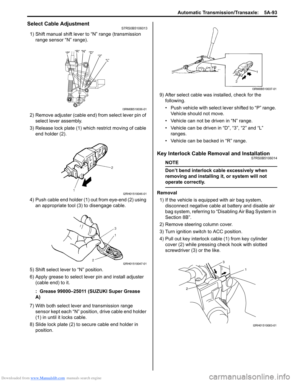
1) Shift manual shift lever to “N” range (transmission range sensor “N” range).
2) Remove adjuster (cable end) from select lever pin of select lever assembly.
3) Release lock plate (1) which restrict moving of cable end holder (2).
4) Push cable end holder (1) out from eye-end (2) using an appropriate tool (3) to disengage cable.
5) Shift select lever to “N” position.
6) Apply grease to select lever pin and install adjuster (cable end) to it.
: Grease 99000–25011 (SUZUKI Super Grease
A)
7) With both select lever and transmission range sensor kept each “N” position, drive cable end holder
(1) in until it locks cable.
8) Slide lock plate (2) to secure cable end holder in position. 9) After select cable was
installed, check for the
following.
• Push vehicle with select lever shifted to “P” range. Vehicle should not move.
• Vehicle can not be driven in “N” range.
• Vehicle can be driven in “D”, “3”, “2” and “L” ranges.
• Vehicle can be backed in “R” range.
Key Interlock Cable Removal and InstallationS7RS0B5106014
NOTE
Don’t bend interlock cable excessively when
removing and installing it, or system will not
operate correctly.
Removal
1) If the vehicle is equipped with air bag system, disconnect negative cable at battery and disable air
bag system, referring to “Disabling Air Bag System in
Section 8B”.
2) Remove steering column cover.
3) Turn ignition switch to ACC position.
4) Pull out key interlock cable (1) from key cylinder cover (2) while pressing check hook with slotted
screwdriver (3) or the like.
“P” “R”
“N”
“D”
“2”
“L”
I3RM0B510036-01
I2RH01510046-01
I2RH01510047-01
I3RM0B510037-01
1
2 3
I2RH01510083-01
Page 739 of 1496
Downloaded from www.Manualslib.com manuals search engine Automatic Transmission/Transaxle: 5A-95
5) Shift select lever to “N” position.
NOTE
If select lever is in “P” position, shift select
lever referring to “Select Lever Inspection”.
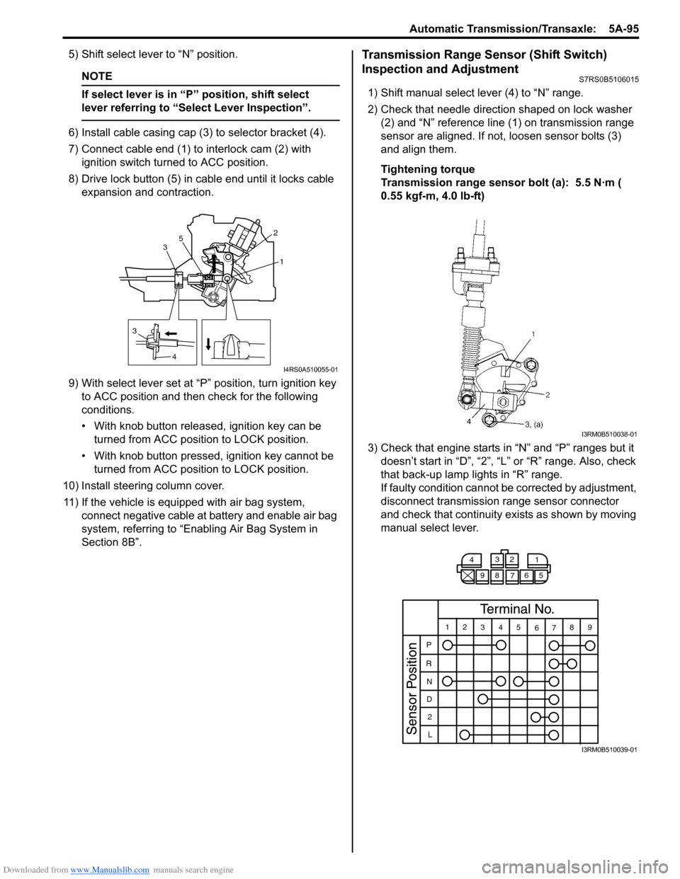
6) Install cable casing cap (3) to selector bracket (4).
7) Connect cable end (1) to interlock cam (2) with ignition switch turned to ACC position.
8) Drive lock button (5) in cable end until it locks cable expansion and contraction.
9) With select lever set at “P ” position, turn ignition key
to ACC position and then check for the following
conditions.
• With knob button released, ignition key can be turned from ACC position to LOCK position.
• With knob button pressed, ignition key cannot be
turned from ACC position to LOCK position.
10) Install steering column cover. 11) If the vehicle is equipped with air bag system, connect negative cable at battery and enable air bag
system, referring to “Enabling Air Bag System in
Section 8B”.
Transmission Range Sensor (Shift Switch)
Inspection and Adjustment
S7RS0B5106015
1) Shift manual select lever (4) to “N” range.
2) Check that needle direction shaped on lock washer (2) and “N” reference line (1) on transmission range
sensor are aligned. If not, loosen sensor bolts (3)
and align them.
Tightening torque
Transmission range sensor bolt (a): 5.5 N·m (
0.55 kgf-m, 4.0 lb-ft)
3) Check that engine starts in “N” and “P” ranges but it doesn’t start in “D”, “2”, “L” or “R” range. Also, check
that back-up lamp lights in “R” range.
If faulty condition cannot be corrected by adjustment,
disconnect transmission range sensor connector
and check that continuity ex ists as shown by moving
manual select lever.
3
4 1
2
3 5
I4RS0A510055-01
I3RM0B510038-01
4
3
2
1
98 76 5
12 345
6789
P
R N
D 2
L
I3RM0B510039-01
Page 744 of 1496
Downloaded from www.Manualslib.com manuals search engine 5A-100 Automatic Transmission/Transaxle:
Operation Check
Shift solenoid valve-A (No.1) and -B (No.2)
CAUTION!
• Do not insert air gun against strainer installed on inlet of solenoid valve too
deeply, when blowing air into solenoid
valve. If not, the strainer will be damaged.
• Be very careful as dust etc. does not enter when solenoid valves are inspected.
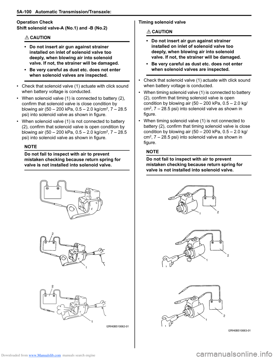
• Check that solenoid valve (1) actuate with click sound when battery voltage is conducted.
• When solenoid valve (1) is connected to battery (2), confirm that solenoid valve is close condition by
blowing air (50 – 200 kPa, 0.5 – 2.0 kg/cm
2, 7 – 28.5
psi) into solenoid valve as shown in figure.
• When solenoid valve (1) is not connected to battery (2), confirm that solenoid valve is open condition by
blowing air (50 – 200 kPa, 0.5 – 2.0 kg/cm
2, 7 – 28.5
psi) into solenoid valve as shown in figure.
NOTE
Do not fail to inspect with air to prevent
mistaken checking because return spring for
valve is not installe d into solenoid valve.
Timing solenoid valve
CAUTION!
• Do not insert air gun against strainer
installed on inlet of solenoid valve too
deeply, when blowing air into solenoid
valve. If not, the strainer will be damaged.
• Be very careful as dust etc. does not enter when solenoid valves are inspected.
• Check that solenoid valve (1) actuate with click sound
when battery voltage is conducted.
• When timing solenoid valve (1 ) is connected to battery
(2), confirm that timing solenoid valve is open
condition by blowing air (50 – 200 kPa, 0.5 – 2.0 kg/
cm
2, 7 – 28.5 psi) into solenoid valve as shown in
figure.
• When timing solenoid valve (1) is not connected to battery (2), confirm that timi ng solenoid valve is close
condition by blowing air (50 – 200 kPa, 0.5 – 2.0 kg/
cm
2, 7 – 28.5 psi) into solenoid valve as shown in
figure.
NOTE
Do not fail to inspect with air to prevent
mistaken checking because return spring for
valve is not installed into solenoid valve.
I2RH0B510062-01I2RH0B510063-01
Page 746 of 1496
Downloaded from www.Manualslib.com manuals search engine 5A-102 Automatic Transmission/Transaxle:
Operation Check
Check pressure control solenoid valves (Pressure
control solenoid and TCC pressure control solenoid)
operation in the either manner of the following.
Using regulated DC power supply
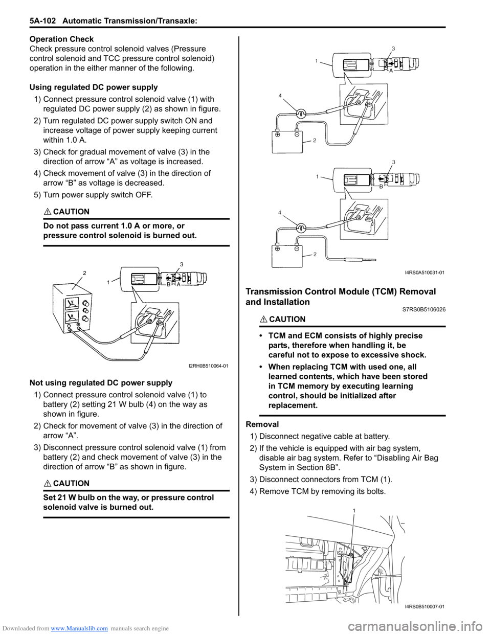
1) Connect pressure contro l solenoid valve (1) with
regulated DC power supply (2) as shown in figure.
2) Turn regulated DC power supply switch ON and increase voltage of power supply keeping current
within 1.0 A.
3) Check for gradual movement of valve (3) in the direction of arrow “A” as voltage is increased.
4) Check movement of valve (3) in the direction of arrow “B” as voltage is decreased.
5) Turn power supply switch OFF.
CAUTION!
Do not pass current 1.0 A or more, or
pressure control solenoid is burned out.
Not using regulated DC power supply 1) Connect pressure control solenoid valve (1) to battery (2) setting 21 W bulb (4) on the way as
shown in figure.
2) Check for movement of valve (3) in the direction of arrow “A”.
3) Disconnect pressure control solenoid valve (1) from battery (2) and check movement of valve (3) in the
direction of arrow “B” as shown in figure.
CAUTION!
Set 21 W bulb on the way, or pressure control
solenoid valve is burned out.
Transmission Control Module (TCM) Removal
and Installation
S7RS0B5106026
CAUTION!
• TCM and ECM consists of highly precise
parts, therefore when handling it, be
careful not to expose to excessive shock.
• When replacing TCM with used one, all learned contents, which have been stored
in TCM memory by executing learning
control, should be initialized after
replacement.
Removal
1) Disconnect negative cable at battery.
2) If the vehicle is equipped with air bag system, disable air bag system. Refer to “Disabling Air Bag
System in Section 8B”.
3) Disconnect connectors from TCM (1).
4) Remove TCM by removing its bolts.
I2RH0B510064-01
I4RS0A510031-01
1
I4RS0B510007-01
Page 747 of 1496
Downloaded from www.Manualslib.com manuals search engine Automatic Transmission/Transaxle: 5A-103
Installation
Reverse removal procedure noting the following.
• Connect TCM connectors securely.
• If the vehicle is equipped with air bag system, be sure to enable air bag system after TCM is back in place.
Refer to “Enabling Air Bag System in Section 8B”.
A/T Relay InspectionS7RS0B5106027
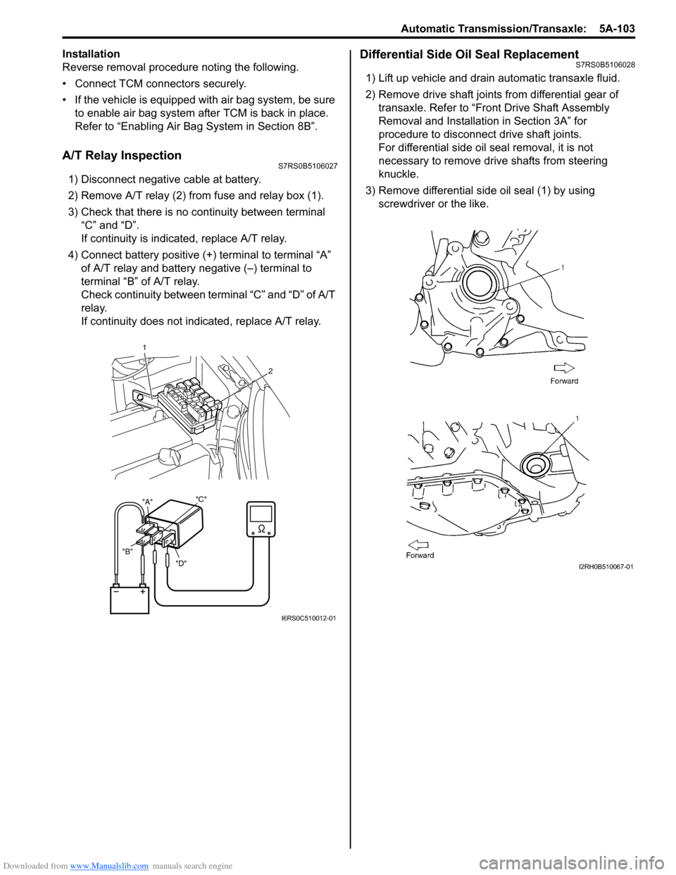
1) Disconnect negative cable at battery.
2) Remove A/T relay (2) from fuse and relay box (1).
3) Check that there is no continuity between terminal “C” and “D”.
If continuity is indicated, replace A/T relay.
4) Connect battery positive (+ ) terminal to terminal “A”
of A/T relay and battery negative (–) terminal to
terminal “B” of A/T relay.
Check continuity between terminal “C” and “D” of A/T
relay.
If continuity does not indicated, replace A/T relay.
Differential Side Oil Seal ReplacementS7RS0B5106028
1) Lift up vehicle and drain automatic transaxle fluid.
2) Remove drive shaft joints from differential gear of transaxle. Refer to “Front Drive Shaft Assembly
Removal and Installation in Section 3A” for
procedure to disconnect drive shaft joints.
For differential side oil seal removal, it is not
necessary to remove drive shafts from steering
knuckle.
3) Remove differential side oil seal (1) by using screwdriver or the like.
"D"
"B" "A"
"C"
1
2
I6RS0C510012-01
I2RH0B510067-01
Page 756 of 1496
Downloaded from www.Manualslib.com manuals search engine 5A-112 Automatic Transmission/Transaxle:
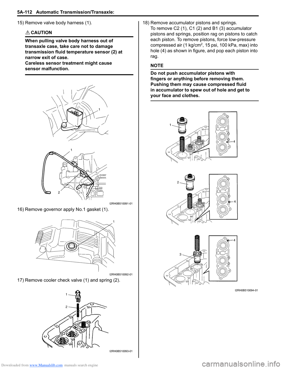
15) Remove valve body harness (1).
CAUTION!
When pulling valve body harness out of
transaxle case, take care not to damage
transmission fluid temperature sensor (2) at
narrow exit of case.
Careless sensor treatment might cause
sensor malfunction.
16) Remove governor apply No.1 gasket (1).
17) Remove cooler check valve (1) and spring (2).18) Remove accumulator pistons and springs.
To remove C2 (1), C1 (2) and B1 (3) accumulator
pistons and springs, position rag on pistons to catch
each piston. To remove pistons, force low-pressure
compressed air (1 kg/cm
2, 15 psi, 100 kPa, max) into
hole (4) as shown in figure, and pop each piston into
rag.
NOTE
Do not push accumulator pistons with
fingers or anything before removing them.
Pushing them may cause compressed fluid
in accumulator to spew out of hole and get to
your face and clothes.
I2RH0B510091-01
I2RH0B510092-01
I2RH0B510093-01
I2RH0B510094-01
Page 762 of 1496
Downloaded from www.Manualslib.com manuals search engine 5A-118 Automatic Transmission/Transaxle:
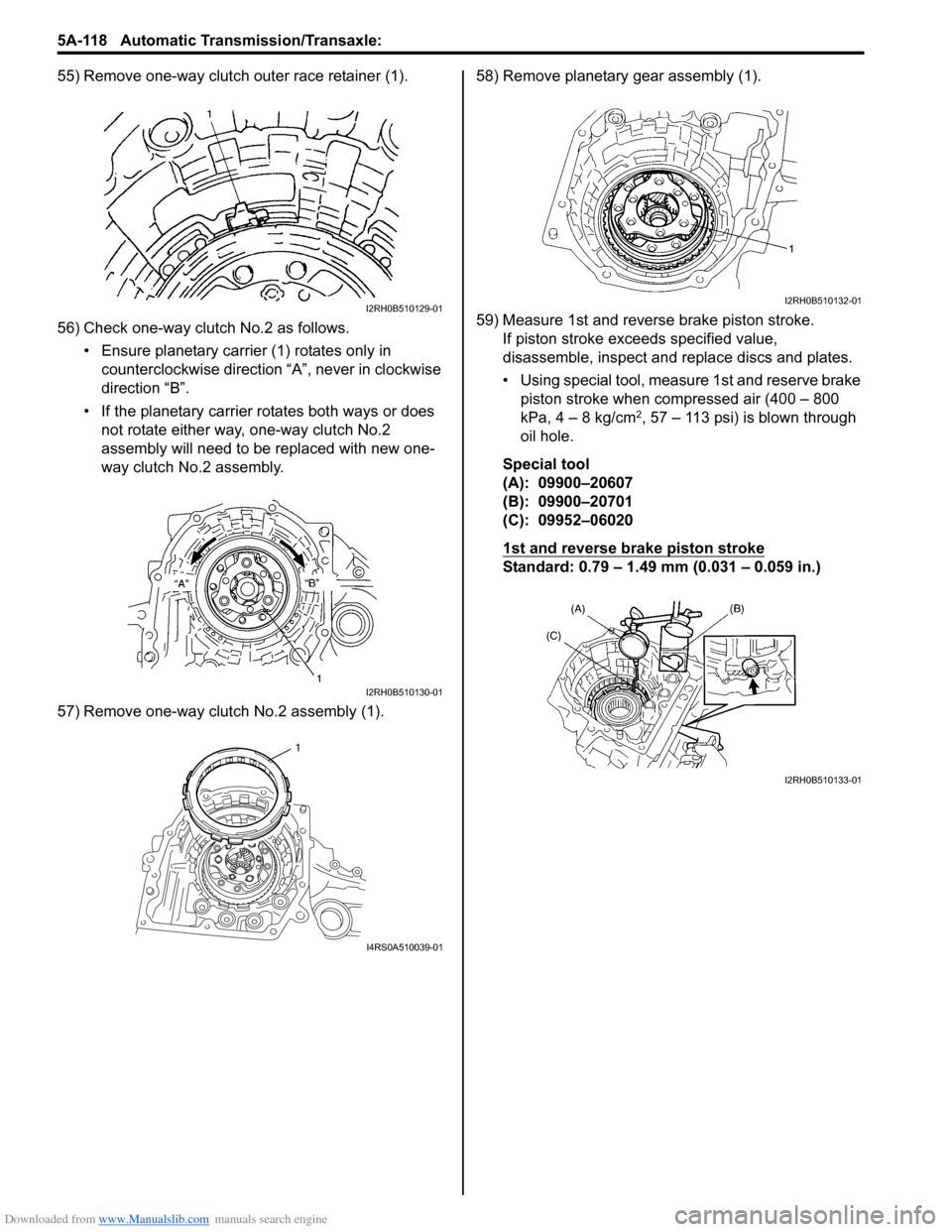
55) Remove one-way clutch outer race retainer (1).
56) Check one-way clutch No.2 as follows.• Ensure planetary carrier (1) rotates only in counterclockwise direction “A”, never in clockwise
direction “B”.
• If the planetary carrier rotates both ways or does not rotate either way, one-way clutch No.2
assembly will need to be replaced with new one-
way clutch No.2 assembly.
57) Remove one-way clutch No.2 assembly (1). 58) Remove planetary gear assembly (1).
59) Measure 1st and reverse brake piston stroke.
If piston stroke exce eds specified value,
disassemble, inspect and replace discs and plates.
• Using special tool, measure 1st and reserve brake piston stroke when compressed air (400 – 800
kPa, 4 – 8 kg/cm
2, 57 – 113 psi) is blown through
oil hole.
Special tool
(A): 09900–20607
(B): 09900–20701
(C): 09952–06020
1st and reverse brake piston stroke
Standard: 0.79 – 1.49 mm (0.031 – 0.059 in.)
I2RH0B510129-01
I2RH0B510130-01
1
I4RS0A510039-01
I2RH0B510132-01
I2RH0B510133-01
Page 764 of 1496
Downloaded from www.Manualslib.com manuals search engine 5A-120 Automatic Transmission/Transaxle:
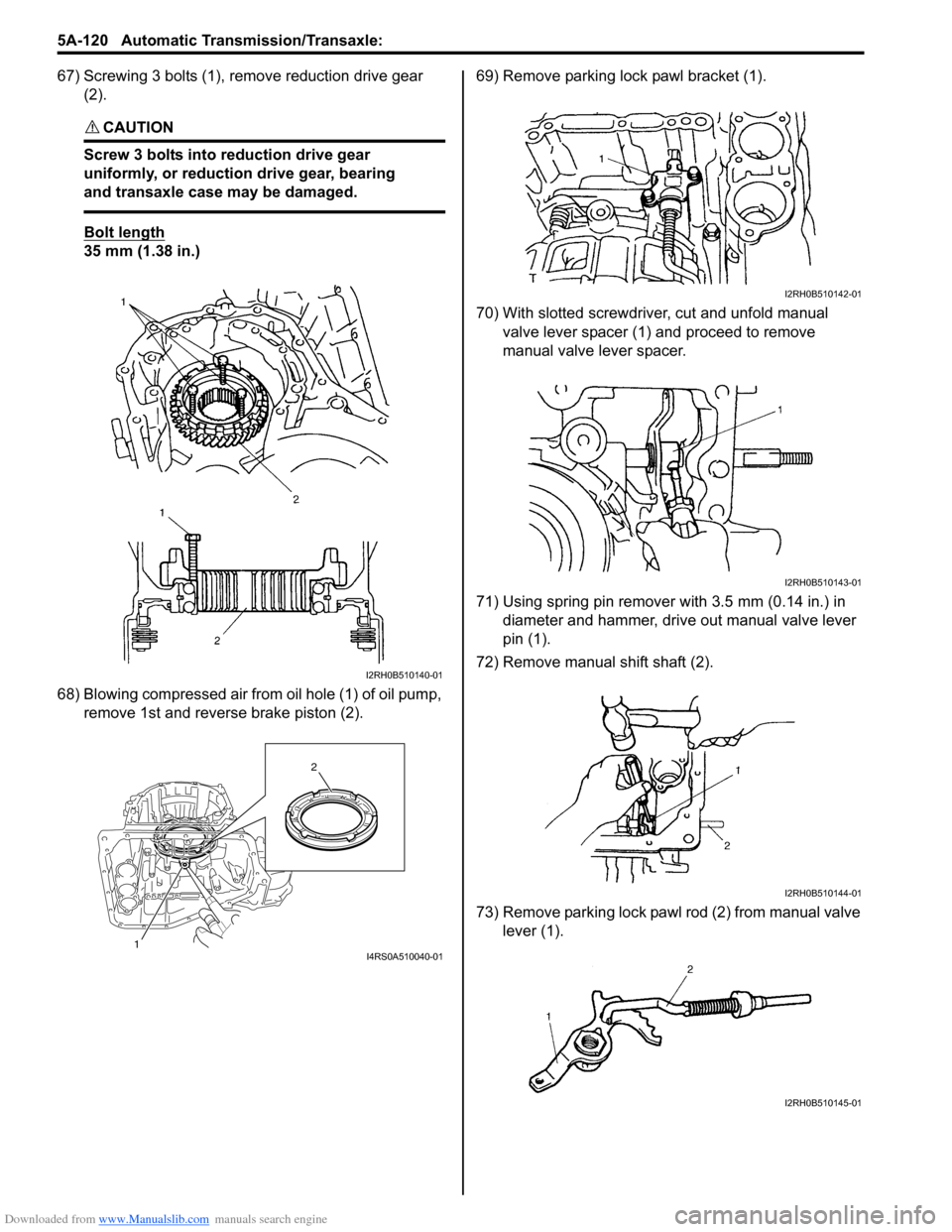
67) Screwing 3 bolts (1), remove reduction drive gear (2).
CAUTION!
Screw 3 bolts into reduction drive gear
uniformly, or reduction drive gear, bearing
and transaxle case may be damaged.
Bolt length
35 mm (1.38 in.)
68) Blowing compressed air from oil hole (1) of oil pump,
remove 1st and reverse brake piston (2). 69) Remove parking lock pawl bracket (1).
70) With slotted screwdriver, cut and unfold manual
valve lever spacer (1) and proceed to remove
manual valve lever spacer.
71) Using spring pin remover with 3.5 mm (0.14 in.) in diameter and hammer, drive out manual valve lever
pin (1).
72) Remove manual shift shaft (2).
73) Remove parking lock pawl rod (2) from manual valve lever (1).
I2RH0B510140-01
1 2I4RS0A510040-01
I2RH0B510142-01
I2RH0B510143-01
I2RH0B510144-01
I2RH0B510145-01
Page 768 of 1496
Downloaded from www.Manualslib.com manuals search engine 5A-124 Automatic Transmission/Transaxle:
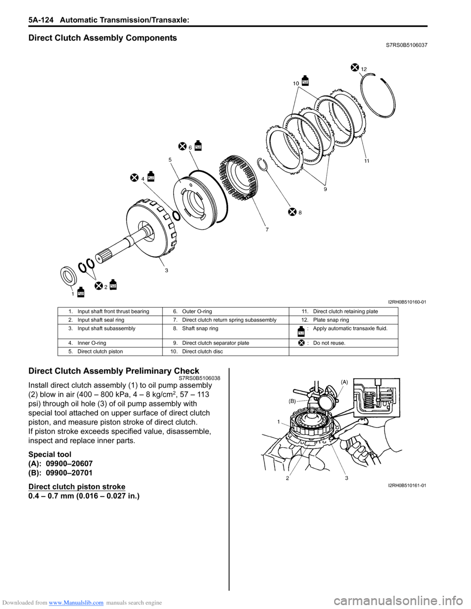
Direct Clutch Assembly ComponentsS7RS0B5106037
Direct Clutch Assembly Preliminary CheckS7RS0B5106038
Install direct clutch assembly (1) to oil pump assembly
(2) blow in air (400 – 800 kPa, 4 – 8 kg/cm2, 57 – 113
psi) through oil hole (3) of oil pump assembly with
special tool attached on uppe r surface of direct clutch
piston, and measure piston stroke of direct clutch.
If piston stroke exceeds sp ecified value, disassemble,
inspect and replace inner parts.
Special tool
(A): 09900–20607
(B): 09900–20701
Direct clutch piston stroke
0.4 – 0.7 mm (0.016 – 0.027 in.)
I2RH0B510160-01
1. Input shaft front thrust bearing 6. Outer O-ring 11. Direct clutch retaining plate
2. Input shaft seal ring 7. Direct clutch return spring subassembly 12. Plate snap ring
3. Input shaft subassembly 8. Shaft snap ring : Apply automatic transaxle fluid.
4. Inner O-ring 9. Direct clutch separator plate : Do not reuse.
5. Direct clutch piston 10. Direct clutch disc
I2RH0B510161-01
Page 769 of 1496
Downloaded from www.Manualslib.com manuals search engine Automatic Transmission/Transaxle: 5A-125
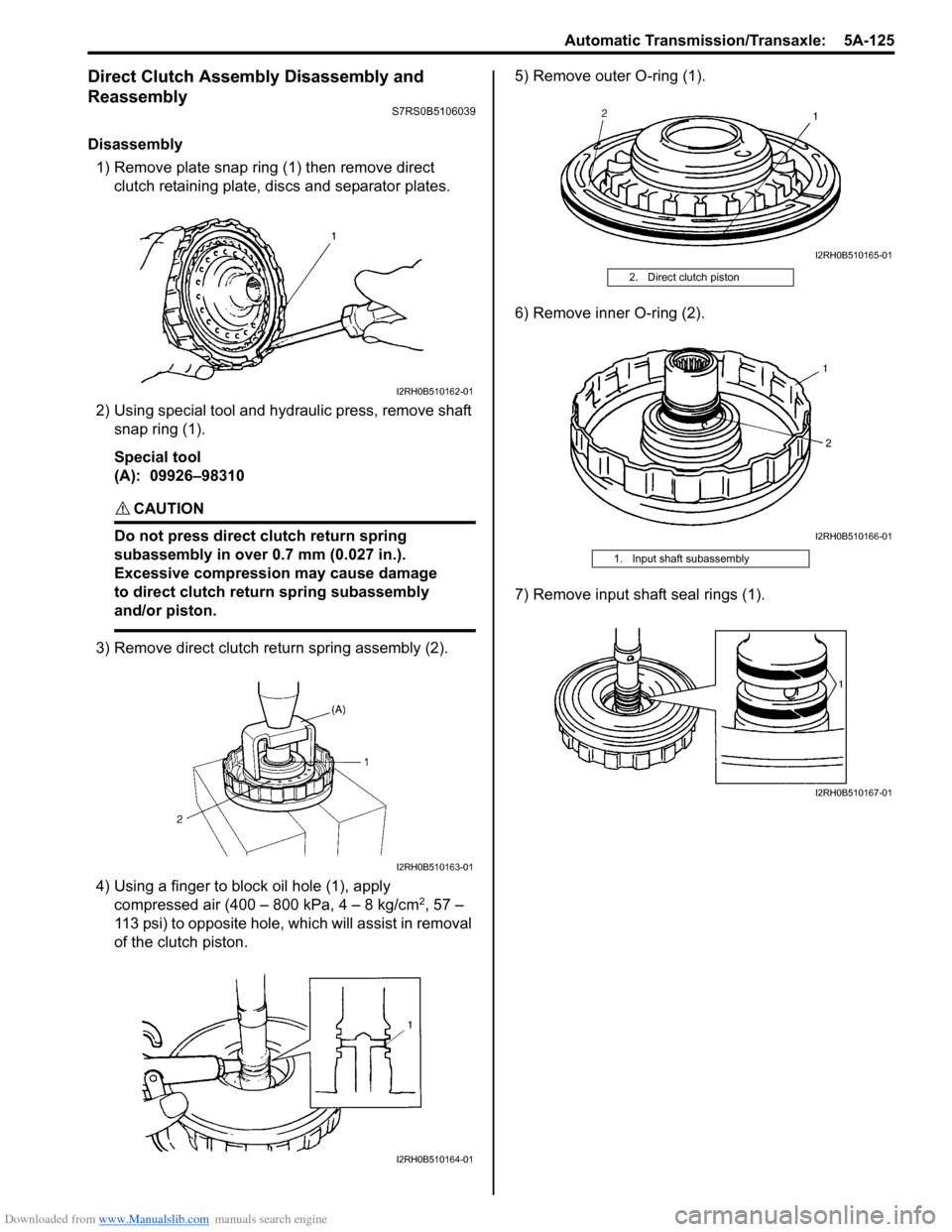
Direct Clutch Assembly Disassembly and
Reassembly
S7RS0B5106039
Disassembly1) Remove plate snap ring (1) then remove direct clutch retaining plate, discs and separator plates.
2) Using special tool and hydraulic press, remove shaft snap ring (1).
Special tool
(A): 09926–98310
CAUTION!
Do not press direct clutch return spring
subassembly in over 0.7 mm (0.027 in.).
Excessive compression may cause damage
to direct clutch return spring subassembly
and/or piston.
3) Remove direct clutch re turn spring assembly (2).
4) Using a finger to block oil hole (1), apply compressed air (400 – 800 kPa, 4 – 8 kg/cm
2, 57 –
113 psi) to opposite hole, which will assist in removal
of the clutch piston. 5) Remove outer O-ring (1).
6) Remove inner O-ring (2).
7) Remove input shaft seal rings (1).
I2RH0B510162-01
I2RH0B510163-01
I2RH0B510164-01
2. Direct clutch piston
1. Input shaft subassembly
I2RH0B510165-01
I2RH0B510166-01
I2RH0B510167-01