Engine diagnos SUZUKI SWIFT 2007 2.G Service Workshop Manual
[x] Cancel search | Manufacturer: SUZUKI, Model Year: 2007, Model line: SWIFT, Model: SUZUKI SWIFT 2007 2.GPages: 1496, PDF Size: 34.44 MB
Page 728 of 1496
Downloaded from www.Manualslib.com manuals search engine 5A-84 Automatic Transmission/Transaxle:
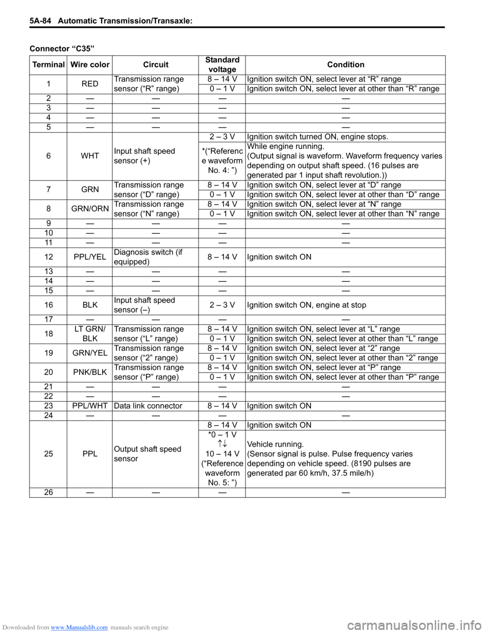
Connector “C35”
Terminal Wire color Circuit Standard
voltage Condition
1RED Transmission range
sensor (“R” range) 8 – 14 V Ignition switch ON, select lever at “R” range
0 – 1 V Ignition switch ON, select lever at other than “R” range
2— — — —
3— — — —
4— — — —
5— — — —
6WHT Input shaft speed
sensor (+) 2 – 3 V Ignition switch turned ON, engine stops.
*(“Referenc
e waveform No. 4: ”) While engine running.
(Output signal is waveform. Waveform frequency varies
depending on output shaft speed. (16 pulses are
generated par 1 input shaft revolution.))
7GRN Transmission range
sensor (“D” range) 8 – 14 V Ignition switch ON, select lever at “D” range
0 – 1 V Ignition switch ON, select lever at other than “D” range
8 GRN/ORN Transmission range
sensor (“N” range) 8 – 14 V Ignition switch ON, select lever at “N” range
0 – 1 V Ignition switch ON, select lever at other than “N” range
9— — — —
10 — — — — 11 — — — —
12 PPL/YEL Diagnosis switch (if
equipped) 8 – 14 V Ignition switch ON
13 — — — —
14 — — — —
15 — — — —
16 BLK Input shaft speed
sensor (–) 2 – 3 V Ignition switch ON, engine at stop
17 — — — —
18 LT G R N /
BLK Transmission range
sensor (“L” range) 8 – 14 V Ignition switch ON, select lever at “L” range
0 – 1 V Ignition switch ON, select lever at other than “L” range
19 GRN/YEL Transmission range
sensor (“2” range) 8 – 14 V Ignition switch ON, select lever at “2” range
0 – 1 V Ignition switch ON, select lever at other than “2” range
20 PNK/BLK Transmission range
sensor (“P” range) 8 – 14 V Ignition switch ON, select lever at “P” range
0 – 1 V Ignition switch ON, select lever at other than “P” range
21 — — — —
22 — — — —
23 PPL/WHT Data link connector 8 – 14 V Ignition switch ON
24 — — — —
25 PPL Output shaft speed
sensor 8 – 14 V Ignition switch ON
*0 – 1 V ↑↓
10 – 14 V
(“Reference waveform No. 5: ”) Vehicle running.
(Sensor signal is pulse. Pulse frequency varies
depending on vehicle speed. (8190 pulses are
generated par 60 km/h, 37.5 mile/h)
26 — — — —
Page 817 of 1496
Downloaded from www.Manualslib.com manuals search engine Manual Transmission/Transaxle: 5B-3
Diagnostic Information and Procedures
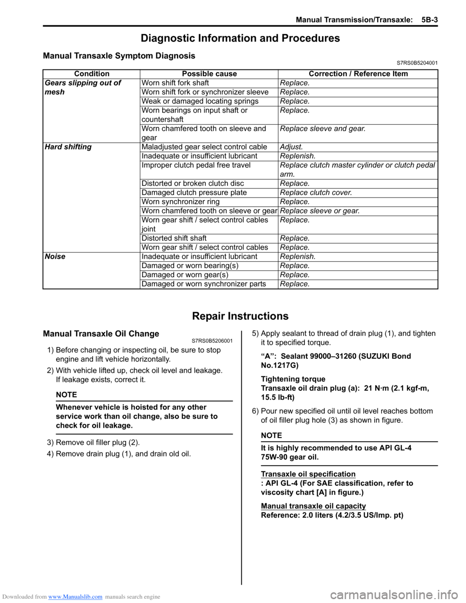
Manual Transaxle Symptom DiagnosisS7RS0B5204001
Repair Instructions
Manual Transaxle Oil ChangeS7RS0B5206001
1) Before changing or inspecting oil, be sure to stop engine and lift vehicle horizontally.
2) With vehicle lifted up, check oil level and leakage. If leakage exists, correct it.
NOTE
Whenever vehicle is hoisted for any other
service work than oil change, also be sure to
check for oil leakage.
3) Remove oil filler plug (2).
4) Remove drain plug (1), and drain old oil. 5) Apply sealant to thread of drain plug (1), and tighten
it to specified torque.
“A”: Sealant 99000–31260 (SUZUKI Bond
No.1217G)
Tightening torque
Transaxle oil drain plug (a): 21 N·m (2.1 kgf-m,
15.5 lb-ft)
6) Pour new specified oil unt il oil level reaches bottom
of oil filler plug hole (3) as shown in figure.NOTE
It is highly recommended to use API GL-4
75W-90 gear oil.
Transaxle oil specification
: API GL-4 (For SAE classification, refer to
viscosity chart [A] in figure.)
Manual transaxle oil capacity
Reference: 2.0 liters (4.2/3.5 US/Imp. pt)
Condition Possible cause Correction / Reference Item
Gears slipping out of
mesh Worn shift fork shaft
Replace.
Worn shift fork or synchronizer sleeve Replace.
Weak or damaged locating springs Replace.
Worn bearings on input shaft or
countershaft Replace.
Worn chamfered tooth on sleeve and
gear Replace sleeve and gear.
Hard shifting Maladjusted gear select control cable Adjust.
Inadequate or insufficient lubricant Replenish.
Improper clutch pedal free travel Replace clutch master cylinder or clutch pedal
arm.
Distorted or broken clutch disc Replace.
Damaged clutch pressure plate Replace clutch cover.
Worn synchronizer ring Replace.
Worn chamfered tooth on sleeve or gear Replace sleeve or gear.
Worn gear shift / select control cables
joint Replace.
Distorted shift shaft Replace.
Worn gear shift / select control cables Replace.
Noise Inadequate or insufficient lubricant Replenish.
Damaged or worn bearing(s) Replace.
Damaged or worn gear(s) Replace.
Damaged or worn synchronizer parts Replace.
Page 854 of 1496
Downloaded from www.Manualslib.com manuals search engine 5C-2 Clutch:
Diagnostic Information and Procedures
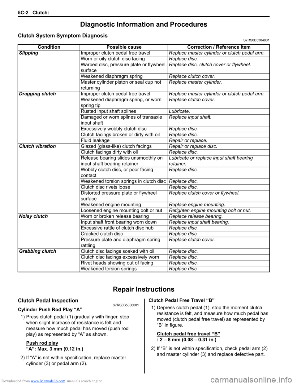
Clutch System Symptom DiagnosisS7RS0B5304001
Repair Instructions
Clutch Pedal InspectionS7RS0B5306001
Cylinder Push Rod Play “A”1) Press clutch pedal (1) gradually with finger, stop when slight increase of resistance is felt and
measure how much pedal has moved (push rod
play) as represented by “A” as shown.
Push rod play
“A”: Max. 3 mm (0.12 in.)
2) If “A” is not within specification, replace master cylinder (3) or pedal arm (2). Clutch Pedal Free Travel “B”
1) Depress clutch pedal (1), stop the moment clutch resistance is felt, and measure how much pedal has
moved (clutch pedal free travel) as represented by
“B” in figure.
Clutch pedal free travel
“B”
: 2 – 8 mm (0.08 – 0.31 in.)
2) If “B” is not within specification, check pedal arm (2) and master cylinder (3) and replace defective part.
Condition Possible cause Correction / Reference Item
Slipping Improper clutch pedal free travel Replace master cylinder or clutch pedal arm.
Worn or oily clutch disc facing Replace disc.
Warped disc, pressure plate or flywheel
surface Replace disc, clutch cover or flywheel.
Weakened diaphragm spring Replace clutch cover.
Master cylinder piston or seal cup not
returning Replace master cylinder.
Dragging clutch Improper clutch pedal free travel Replace master cylinder or clutch pedal arm.
Weakened diaphragm spring, or worn
spring tip Replace clutch cover.
Rusted input shaft splines Lubricate.
Damaged or worn splines of transaxle
input shaft Replace input shaft.
Excessively wobbly clutch disc Replace disc.
Clutch facings broken or dirty with oil Replace disc.
Fluid leakage Repair or replace.
Clutch vibration Glazed (glass-like) clutch facings Repair or replace disc.
Clutch facings dirty with oil Replace disc.
Release bearing slides unsmoothly on
input shaft bearing retainer Lubricate or replace input shaft bearing
retainer.
Wobbly clutch disc, or poor facing
contact Replace disc.
Weakened torsion springs in clutch disc Replace disc.
Clutch disc rivets loose Replace disc.
Distorted pressure plate or flywheel
surface Replace clutch cover or flywheel.
Weakened engine mounting Replace engine mounting.
Loosened engine mounting bolt or nut Retighten engine mounting bolt or nut.
Noisy clutch Worn or broken release bearing Replace release bearing.
Input shaft front bearing worn down Replace input shaft bearing.
Excessive rattle of clutch disc hub Replace disc.
Cracked clutch disc Replace disc.
Pressure plate and diaphragm spring
rattling Replace clutch cover.
Grabbing clutch Clutch disc facings soaked with oil Replace disc.
Clutch disc facings excessively worn Replace disc.
Rivet heads showing out of facing Replace disc.
Weakened torsion springs Replace disc.
Page 867 of 1496

Downloaded from www.Manualslib.com manuals search engine Table of Contents 6- i
6
Section 6
CONTENTS
Steering
Precautions ................................................. 6-1
Precautions............................................................. 6-1
Precautions on Steering........................................ 6-1
Steering General Diagnosi s.................... 6A-1
Precautions........................................................... 6A-1
Precautions for Steering Diagnosis ..................... 6A-1
Diagnostic Information and Procedures ............ 6A-2 Steering Symptom Diagnosis .............................. 6A-2
Steering Wheel and Column ................... 6B-1
Precautions........................................................... 6B-1
Service Precautions of Steering Wheel and Column.............................................................. 6B-1
General Description ............................................. 6B-1 Steering Wheel and Column Construction .......... 6B-1
Diagnostic Information and Procedures ............ 6B-2 Checking Steering Column for Accident Damage ............................................................ 6B-2
Repair Instructions .............................................. 6B-3 Steering Wheel and Column Construction .......... 6B-3
Steering Wheel Removal and Installation ........... 6B-4
Contact Coil Cable Assembly Removal and Installation ......................................................... 6B-5
Centering Contact Coil Cable Assembly ............. 6B-6
Contact Coil Cable Assembly Inspection ............ 6B-6
Steering Angle Sensor Removal and Installation ......................................................... 6B-6
Steering Angle Sensor Inspection ....................... 6B-6
Steering Column Removal and Installation ......... 6B-7
Steering Column Inspecti on ................................ 6B-8
Ignition Switch Cylinder Assembly Removal and Installation (Non- Keyless Start Model)...... 6B-9
Steering Lock Assembly (Ignition Switch) Removal and Installation................................... 6B-9
Steering Lower Shaft Removal and Installation ....................................................... 6B-10
Specifications ..................................................... 6B-11
Tightening Torque Specifications ...................... 6B-11
Special Tools and Equipmen t ........................... 6B-11
Special Tool ...................................................... 6B-11
Power Assisted Steering System........... 6C-1
Precautions........................................................... 6C-1 Steering System Note .........................................6C-1
Precautions in Diagnosing Troubles ...................6C-1
General Description .............................................6C-2 P/S System Description ......................................6C-2
EPS Diagnosis General Descr iption ...................6C-3
On-Board Diagnostic System Description ...........6C-3
Schematic and Routing Diagram ........................6C-4 EPS System Wiring Circuit Diagram ...................6C-4
Diagnostic Information and Procedures ............6C-5 EPS System Check .............. ...............................6C-5
“EPS” Warning Light Check . ...............................6C-8
DTC Check..........................................................6C-8
DTC Clearance ...................................................6C-9
DTC Table ...........................................................6C-9
Scan Tool Data .................................................6C-11
Visual Inspection ...............................................6C-12
P/S System Symptom Diagnosis ......................6C-12
Serial Data Link Circuit Check ..........................6C-13
“EPS” Warning Light Do es Not Come ON with
Ignition Switch Turn ed ON before Engine
Starts ...............................................................6C-15
“EPS” Warning Light Remains ON Steady after Engine Starts ..........................................6C-16
DTC C1113: Steering Torque Sensor (Main and Sub) Circuit Correlation ............................6C-17
DTC C1114: Steering Torque Sensor Reference Power Supply Circuit .....................6C-19
DTC C1117: Steering Torque Sensor Failure Signal Circuit Low ...........................................6C-21
DTC C1118: Steering Torque Sensor Failure Signal Circuit High...........................................6C-22
DTC C1119: Steering Torque Sensor Power Supply Circuit ..................................................6C-24
DTC C1121 / C1123 / C1124: VSS Circuit
Failure .............................................................6C-26
DTC C1122: Engine Speed Signal....................6C-28
DTC C1141 / C1142 / C1143 / C1145: P/S Motor Circuit Failure ........................................6C-30
DTC C1153: P/S Control Module Power Supply Circuit Voltage Low .............................6C-32
DTC C1155: P/S Control Module Failure ..........6C-33
P/S Control Module Power Supply and Ground Circuit Check ......................................6C-34
Inspection of P/S Control Module and Its Circuits ............................................................6C-35
Page 869 of 1496
Downloaded from www.Manualslib.com manuals search engine Precautions: 6-1
Steeri ng
Precautions
Precautions
Precautions on SteeringS7RS0B6000001
Air Bag Warning
Refer to “Air Bag Warning in Section 00”.
Air Bag System Service Warning
Refer to “Air Bag System Service Warning in Section 00”.
Precautions for Steering Diagnosis
Refer to “Precautions for Steering Diagnosis in Section 6A”.
Service Precautions of Steering Wheel and Column
Refer to “Service Precautions of Steering Wheel and Column in Section 6B”.
P/S System Note
Refer to “Steering System Note in Section 6C”.
Page 870 of 1496
Downloaded from www.Manualslib.com manuals search engine 6A-1 Steering General Diagnosis:
Steeri ng
Steering General Diagnosis
Precautions
Precautions for Steering DiagnosisS7RS0B6100001
Since the problems in steering involve several systems, they must all be considered when diagnosing a complaint. To
avoid using the wrong symptom, always road test the vehicl e first. Proceed with the following preliminary inspection
and correct any defects which are found.
1) Inspect tires for proper pressure and uneven wear.
2) Raise vehicle on a hoist and inspect steering system for loose or damaged parts.
3) Spin front wheels. Inspect for out-of-round tires, out- of-balance tires, bent rims, loosen and/or rough wheel
bearings.
Page 871 of 1496

Downloaded from www.Manualslib.com manuals search engine Steering General Diagnosis: 6A-2
Diagnostic Information and Procedures
Steering Symptom DiagnosisS7RS0B6104001
ConditionPossible cause Correction / Reference Item
Hard steering Tire not adequately inflated Inflate tires to proper pressure.
Malfunction of power steering system Check and correct.
Bind in tie-rod end ball studs or lower
ball joints Replace tie-rod end or front suspension arm.
Disturbed front wheel alignment Check and adjust front wheel alignment.
Bind in steering column Repair or replace steering column.
Rack and pinion adjustment Check and adjustment rack and pinion torque.
Too much play in steering Wheel bearings worn Replace wheel bearing.
Loose steering gear case bolts Tighten gear case bolts.
Faulty steering gear case assembly Replace steering gear case assembly.
Worn steering shaft joints Replace joint.
Worn tie-rod ends or tie-rod inside ball
joints Replace tie-rod end or tie-rod.
Worn lower ball joints Replace front suspension control arm.
Rack and pinion adjustment Check and adjustment rack and pinion torque.
Poor return ability Bind in tie-rod end ball studs Replace tie-rod end.
Bind in ball joints Replace front suspension control arm.
Bind in steering column Repair or replace steering column.
Disturbed front end alignment Check and adjust front end alignment.
Faulty steering gear case assembly Replace steering gear case assembly.
Tires not adequately inflated Adjust tire pressure.
Rack and pinion adjustment Check and adjustment rack and pinion torque.
Rack and pinion noise
(Rattle or chuckle) Loose steering gear case bolts
Tighten steering gear case bolts.
Rack and pinion adjustment Check and adjustment rack and pinion torque.
Faulty steering gear case assembly Replace steering gear case assembly.
Broken or other wise damaged wheel
bearing(s) Replace wheel bearing(s).
Wander or poor steering
stability Mismatched or uneven tires
Replace or inflate tires to proper pressure.
Loosen ball joints and tie-rod ends Replace suspension control arm or tie-rod end.
Faulty struts or mountings Replace strut or repair mounting.
Loose stabilizer bar Tighten or replace stabilizer bar or bush.
Broken or sagging springs Replace spring.
Rack and pinion adjustment Check and adjustment rack and pinion torque.
Disturbed front wheel alignment Check and adjust front wheel alignment.
Faulty steering gear case assembly Replace steering gear case assembly.
Erratic steering when
braking Worn wheel bearing(s)
Replace wheel bearing(s).
Broken or sagging spring(s) Replace coil spring(s).
Wheel tires are inflated unequally Inflate tires to proper pressure.
Disturbed front wheel alignment Check and adjust front wheel alignment.
Brakes not working in unison Check and repair brake system.
Leaking caliper Repair or replace caliper.
Warped discs Replace brake disc.
Badly worn brake pads Replace brake pads.
Page 872 of 1496
Downloaded from www.Manualslib.com manuals search engine 6B-1 Steering Wheel and Column:
Steeri ng
Steering Wheel and Column
Precautions
Service Precautions of Steering Wheel and
Column
S7RS0B6200001
For service precautions, refer to “Precautions on Service
and Diagnosis of Air Bag System in Section 8B”.
Service and Diagnosis
For diagnosis and servicing, refer to “Precautions on
Service and Diagnosis of Air Bag System in Section 8B”.
Disabling Air Bag System
For disabling air bag system, refer to “Disabling Air Bag
System in Section 8B”. Enabling Air Bag System
For enabling air bag system, refer to “Enabling Air Bag
System in Section 8B”.
Handling and Storage
For handling and storage, refer to “Precautions on
Handling and Storage of Air Bag System Components in
Section 8B”.
Disposal
For disposal, refer to “Prec
autions on Disposal of Air
Bag and Seat Belt Pretensioner in Section 8B”.
General Description
Steering Wheel and Column ConstructionS7RS0B6201001
This double tube type steering column has the following three important features in addition to the steering function:
• The column is energy absorbing, desig ned to compress in a front-end collision.
• The ignition switch and lock are mounted conveniently on this column.
• With the column mounted lock, the ignition and steering op erations can be locked to inhibit theft of the vehicle.
To insure the energy absorbing action, it is important th at only the specified screws, bolts and nuts be used as
designated, and that they are tightened to the specified torque. When the column assembly is removed from the
vehicle, special care must be taken in handling it. Use of a steering wheel puller or a sharp blow on the end of the
steering shaft, leaning on the assembly, or dropping the a ssembly could shear the plastic shear pins which maintain
column length and position.
The driver air bag (inflator) module is one of the supplemental restraint (air bag) system components and is mounted
to the center of the steering wheel. During certain frontal crashes, the air bag system supplements the restraint of the
driver’s and passenger’s seat belts by deploying the air b ags. The air bag (inflator) module should be handled with
care to prevent accidental deployment. When servicing, be sure to observe “Precautions on Service and Diagnosis of
Air Bag System in Section 8B”.
Page 873 of 1496
Downloaded from www.Manualslib.com manuals search engine Steering Wheel and Column: 6B-2
Diagnostic Information and Procedures
Checking Steering Column for Accident
Damage
S7RS0B6204001
NOTE
Vehicles involved in accidents resulting in
body damage, where steering column has
been impacted or air bag deployed may have
a damaged or misaligned steering column.
Checking Procedure
NOTE
The steering column used in each vehicle is
one of the two types as shown.
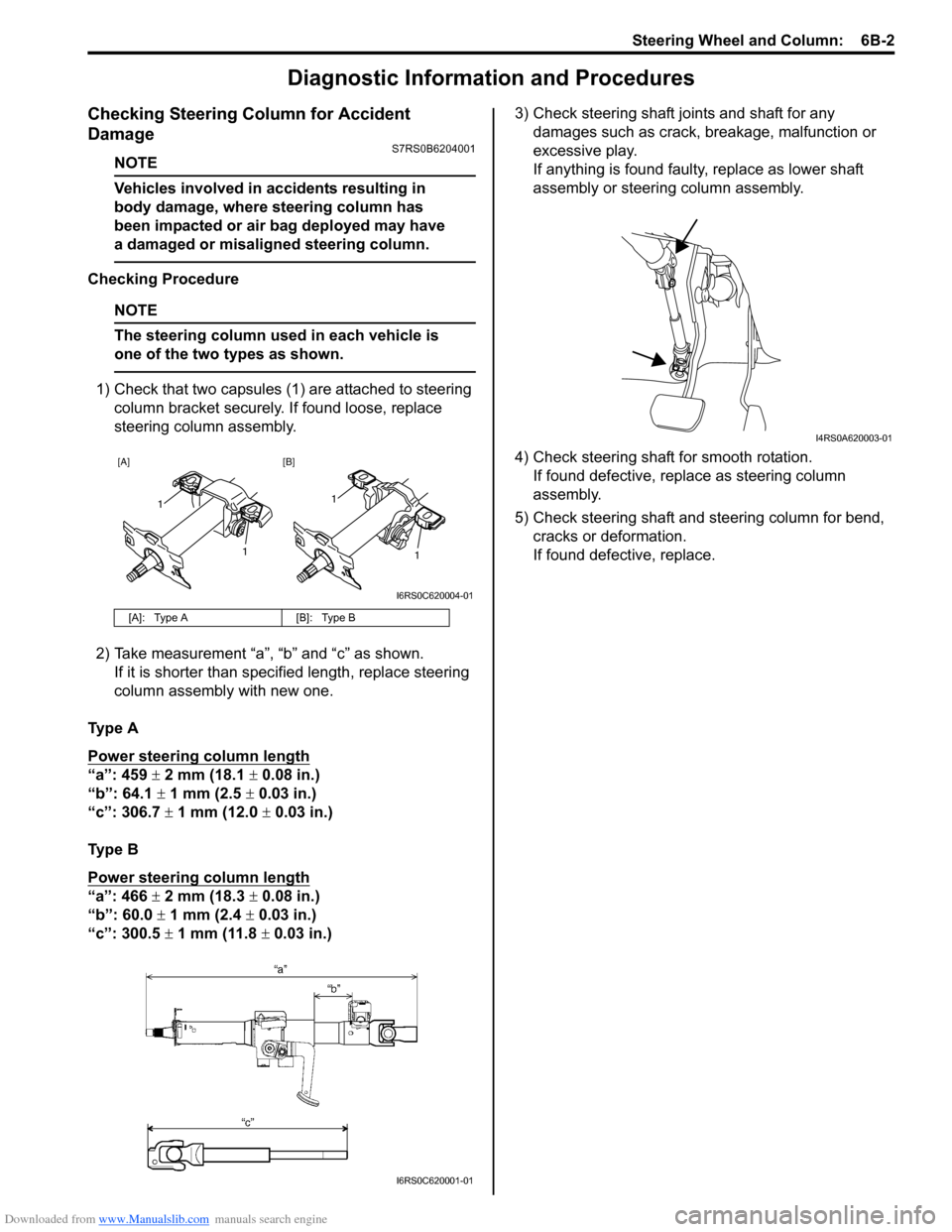
1) Check that two capsules (1) are attached to steering column bracket securely. If found loose, replace
steering column assembly.
2) Take measurement “a”, “b” and “c” as shown. If it is shorter than spec ified length, replace steering
column assembly with new one.
Ty p e A
Power steering column length
“a”: 459 ± 2 mm (18.1 ± 0.08 in.)
“b”: 64.1 ± 1 mm (2.5 ± 0.03 in.)
“c”: 306.7 ± 1 mm (12.0 ± 0.03 in.)
Ty p e B
Power steering column length
“a”: 466 ± 2 mm (18.3 ± 0.08 in.)
“b”: 60.0 ± 1 mm (2.4 ± 0.03 in.)
“c”: 300.5 ± 1 mm (11.8 ± 0.03 in.) 3) Check steering shaft joints and shaft for any
damages such as crack, breakage, malfunction or
excessive play.
If anything is found faulty, replace as lower shaft
assembly or steering column assembly.
4) Check steering shaft for smooth rotation. If found defective, replace as steering column
assembly.
5) Check steering shaft and steering column for bend, cracks or deformation.
If found defective, replace.
[A]: Type A [B]: Type B
[A] [B]
1
1
1
1
I6RS0C620004-01
I6RS0C620001-01
I4RS0A620003-01
Page 883 of 1496
Downloaded from www.Manualslib.com manuals search engine Power Assisted Steering System: 6C-1
Steeri ng
Power Assisted Steering System
Precautions
Steering System NoteS7RS0B6300001
NOTE
All steering gear fasteners are important attaching parts in that they could affect the performance of
vital parts and systems, and/or could result in major repair expense. They must be replaced with one of
the same part number or with an equivalent part if replacement becomes necessary. Do not use a
replacement part of lesser quality or substitute design. Torque values must be used as specified
during reassembly to assure proper retention of these parts.
Precautions in Diagnosing TroublesS7RS0B6300002
• Take a note of DTC indicated on the SUZUKI scan tool.
• Before inspection, be sure to read “Pre cautions for Electrical Circuit Service in Section 00” and understand what is
written there.
• DTC C1122 (engine speed signal failure) is indicated when ignition switch is at ON position and engine is not
running, but it means there is nothing abnormal if indica tion changes to a normal one when engine is started.
• As DTC is stored in memory of the P/S control module, be sure to clear memory after repair by performing the
procedure described in “DTC Clearance”.