wiring SUZUKI SWIFT 2007 2.G Service Workshop Manual
[x] Cancel search | Manufacturer: SUZUKI, Model Year: 2007, Model line: SWIFT, Model: SUZUKI SWIFT 2007 2.GPages: 1496, PDF Size: 34.44 MB
Page 1279 of 1496
Downloaded from www.Manualslib.com manuals search engine Wiring Systems: 9A-108
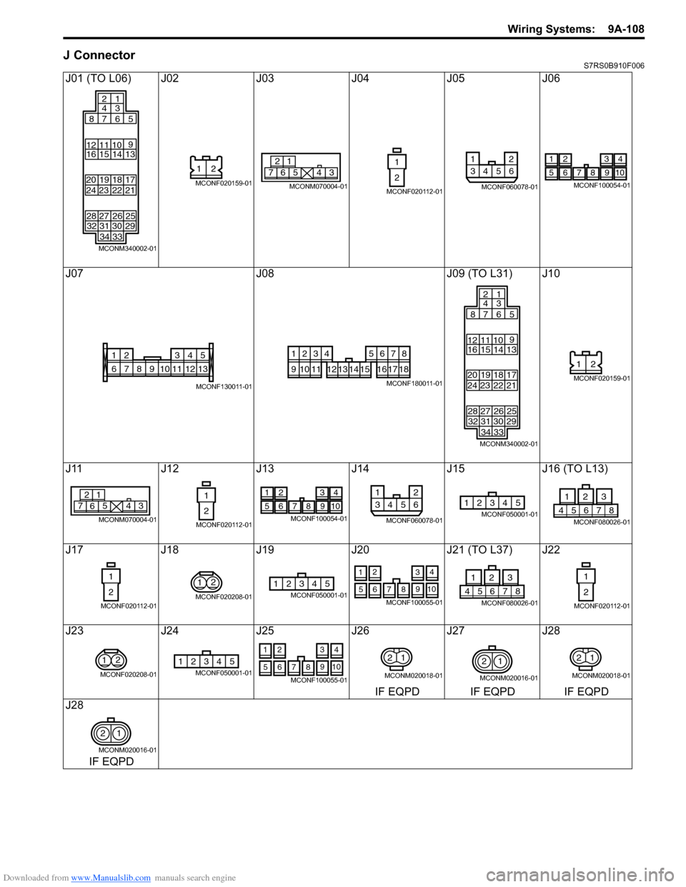
J ConnectorS7RS0B910F006
J01 (TO L06) J02J03J04J05J06
J07 J08J09 (TO L31) J10
J11 J12J13J14 J15 J16 (TO L13)
J17 J18J19 J20 J21 (TO L37) J22
J23 J24J25 J26 J27 J28
IF EQPD IF EQPD IF EQPD
J28
IF EQPD
313234 33 30 29
24
28 23
27 22
26 21
25
16
20 19 15
12 11 10
14
1813
17
87 6
2
4
1
3
5
9
MCONM340002-01
21
MCONF020159-016
21
7543
MCONM070004-01
1
2
MCONF020112-01
12
3456
MCONF060078-01
1234
5678910
MCONF100054-01
135
68910111324
712
MCONF130011-01
1234
91011
5678
12131415161718
MCONF180011-01
3132 34 33 30 29
24
28 23
27 22
26 21
25
16
20 19 15
12 11 10
14
1813
17
87 6
2
4
1
3
5
9
MCONM340002-01
21
MCONF020159-01
6
21
7543
MCONM070004-01
1
2
MCONF020112-01
1234
5678910
MCONF100054-01
12
3456
MCONF060078-01
12345MCONF050001-0187654
231
MCONF080026-01
1
2
MCONF020112-01
2
1
MCONF020208-01
12345MCONF050001-01
2
1 4
3
7 9
65 108
MCONF100055-0187654
231
MCONF080026-01
1
2
MCONF020112-01
2
1
MCONF020208-01
12345MCONF050001-01
2
1 4
3
7 9
65 108
MCONF100055-01
12
MCONM020018-01
2
1
MCONM020016-01
12
MCONM020018-01
21
MCONM020016-01
Page 1280 of 1496
Downloaded from www.Manualslib.com manuals search engine 9A-109 Wiring Systems:
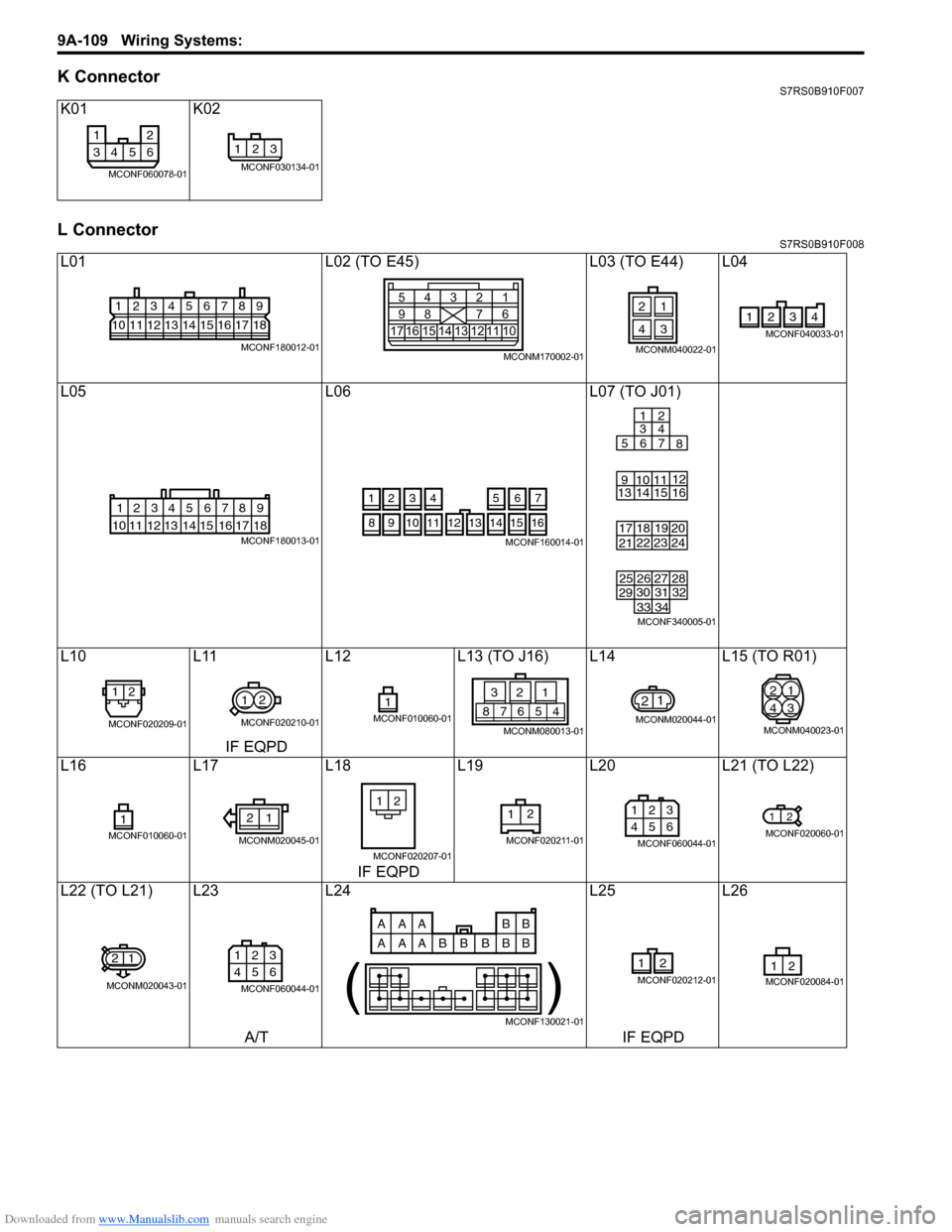
K ConnectorS7RS0B910F007
L ConnectorS7RS0B910F008
K01K02
L01 L02 (TO E45)L03 (TO E44) L04
L05 L06L07 (TO J01)
L10 L11L12L13 (TO J16) L14 L15 (TO R01)
IF EQPD
L16 L17L18L19L20 L21 (TO L22)
IF EQPD
L22 (TO L21) L23 L24L25L26
A/T IF EQPD
12
3456
MCONF060078-01
123
MCONF030134-01
123456789
101112131415161718
MCONF180012-01175
9161312 11 101514
4
832
71
6
MCONM170002-01
21
43
MCONM040022-01
2341
MCONF040033-01
123456789
15 16 17 18
1110 12 13 14
MCONF180013-01
4
3
56
1214
11
10 15
721
13
16
98
MCONF160014-01
31 32
3433
30
29
24
28
23
27
22
26
21
25
13 2019
14
91011
15
18 16
17 7
1
3
2
4
56 8
12
MCONF340005-01
12
MCONF020209-01
1 2
MCONF020210-01
1MCONF010060-0145678
213
MCONM080013-01
21
MCONM020044-01
2
4 1
3
MCONM040023-01
1MCONF010060-01
12
MCONM020045-01
21
MCONF020207-01
12
MCONF020211-01
1 23
456
MCONF060044-01
12
MCONF020060-01
21
MCONM020043-01
1 23
456
MCONF060044-01
AAA BB
AAA B
BB
BB
( )
MCONF130021-01
12
MCONF020212-0121MCONF020084-01
Page 1281 of 1496

Downloaded from www.Manualslib.com manuals search engine Wiring Systems: 9A-110
L27L28 (TO L44) L29
L30 L31 (TO J09) L32 (TO G04) L33 (TO G03) L34
IF EQPD
L35 L36L37 (TO J21) L38 L39L40
IF EQPD
L41 L42 (TO O01) L43 L44 (TO L28) L46 L47
IF EQPD
L48 L51 (TO G43) L53L59 L60
LHD LHD
L61 L62L63L64L65 L66
LHD LHDLHDLHDIF EQPD IF EQPD
L69 L70 (TO M01) L74
IF EQPD
1MCONF010021-01
1 23
456
MCONF060044-0127 28 29 30 31 32 33 34 3536 37 38 39 40 41 42 43 4445 46 47 48 49 50 51
234567 891011 12 13 14 15 16 17 18 1920 21 22 23 24 25 26
1
MCONF510002-01
12
MCONF020212-01
31 32 3433
30
29
24
28
23
27
22
26
21
25
13 2019
14
91011
15
18 16
17 7
1
3
2
4
56 8
12
MCONF340005-01
4321
MCONF040099-01
234
1 5678 910
20191817161514131211
MCONF200003-01
1MCONF010060-01
12
MCONF020210-01
12
MCONF020209-0145678
213
MCONM080013-01
21
MCONM020044-01
1
MCONM010004-011MCONF010060-01
21
MCONF020207-01
45678
213
MCONM080013-01
1
23
456
MCONF060044-01
123
4
65
MCONM060012-01
1
2
MCONF020116-01
1
2
MCONF020013-01
1
2
MCONF020013-01
12567
8
9 1011121314
34
MCONF140012-01
21MCONF020084-01
12
MCONF020266-01
12
MCONF020060-01
12
34
MCONF040143-01
12
34
MCONF040143-01
12
3456
MCONF060025-01
12
3456
MCONF060025-01
21
MCONF020228-01
21
MCONF020228-01
12
3456
MCONF060025-01
2
4 1
3
MCONM040027-01
123 45
678 12 1110
91 3
( )
MCONF130026-01
Page 1282 of 1496
Downloaded from www.Manualslib.com manuals search engine 9A-111 Wiring Systems:
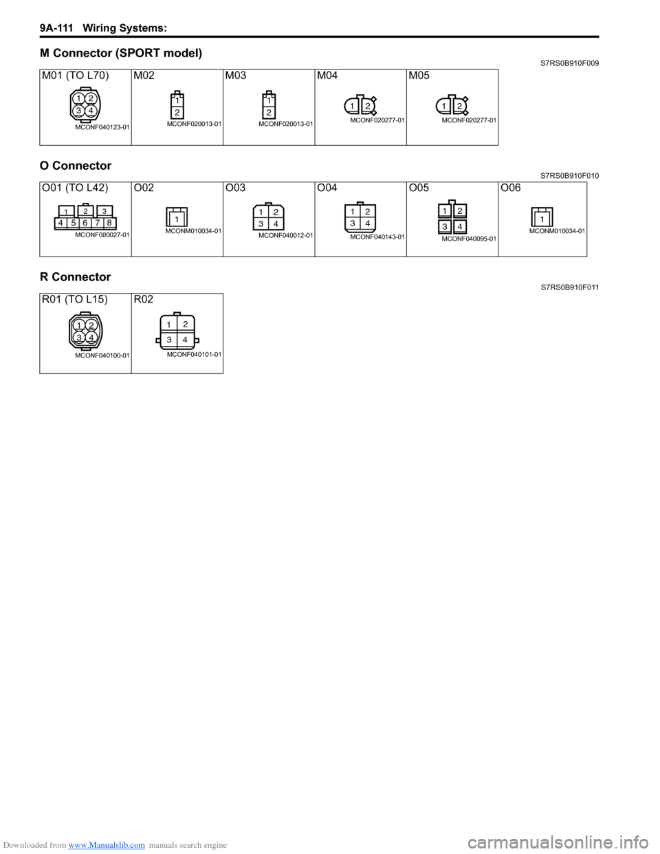
M Connector (SPORT model)S7RS0B910F009
O ConnectorS7RS0B910F010
R ConnectorS7RS0B910F011
M01 (TO L70) M02M03M04M05
O01 (TO L42) O02 O03O04 O05 O06
R01 (TO L15) R02
1
3 2
4
MCONF040123-01
1
2
MCONF020013-01
1
2
MCONF020013-01
1 2
MCONF020277-01
12
MCONF020277-01
3
2
1
45678
MCONF080027-01
1
MCONM010034-01
12
34
MCONF040012-01
12
34
MCONF040143-01
12
34
MCONF040095-01
1
MCONM010034-01
1
3 2
4
MCONF040100-01
1 2
34
MCONF040101-01
Page 1284 of 1496
Downloaded from www.Manualslib.com manuals search engine 9B-2 Lighting Systems:
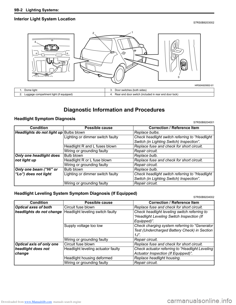
Interior Light System LocationS7RS0B9203002
Diagnostic Information and Procedures
Headlight Symptom DiagnosisS7RS0B9204001
Headlight Leveling System Symptom Diagnosis (If Equipped)S7RS0B9204002
13
2
4
I4RS0A920002-01
1. Dome light 3. Door switches (both sides)
2. Luggage compartment light (if equipped) 4. Rear end door switch (included in rear end door lock)
ConditionPossible cause Correction / Reference Item
Headlights do not light up Bulbs blown Replace bulbs.
Lighting or dimmer switch faulty Check headlight switch referring to “Headlight
Switch (in Lighting Switch) Inspection”.
Headlight R and L fuses blown Replace fuse and check for short circuit.
Wiring or grounding faulty Repair circuit.
Only one headlight does
not light up Bulb blown
Replace bulb.
Headlight R or L fuse blown Replace fuse and check for short circuit.
Wiring or grounding faulty Repair circuit.
Only one beam (“Hi” or
“Lo”) does not light Bulb blown
Replace bulb.
Lighting or dimmer switch faulty Check headlight switch referring to “Headlight
Switch (in Lighting Switch) Inspection”.
Wiring or grounding faulty Repair circuit.
ConditionPossible cause Correction / Reference Item
Optical axes of both
headlights do not change Circuit fuse blown
Replace fuse and check for short circuit.
Headlight leveling switch faulty Check headlight leveling switch referring to
“Headlight Leveling Switch Inspection (If
Equipped)”.
Supply voltage too low Check charging system referring to “Generator
Test (Undercharged Battery Check) in Section
1J”.
Wiring or grounding faulty Repair circuit.
Optical axis of only one
headlight does not
change Circuit fuse blown
Replace fuse and check for short circuit.
Headlight leveling actuator faulty Check actuator referring to “Headlight Leveling
Actuator Inspection (If Equipped)”.
Headlight housing deformed Replace headlight housing.
Wiring or grounding faulty Repair circuit.
Page 1285 of 1496
Downloaded from www.Manualslib.com manuals search engine Lighting Systems: 9B-3
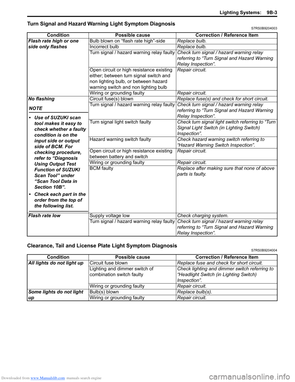
Turn Signal and Hazard Warning Light Symptom DiagnosisS7RS0B9204003
Clearance, Tail and License Plate Light Symptom DiagnosisS7RS0B9204004
ConditionPossible cause Correction / Reference Item
Flash rate high or one
side only flashes Bulb blown on “flash rate high”-side
Replace bulb.
Incorrect bulb Replace bulb.
Turn signal / hazard warning relay faulty Check turn signal / hazard warning relay
referring to “Turn Signal and Hazard Warning
Relay Inspection”.
Open circuit or high resistance existing
either; between turn signal switch and
non lighting bulb, or between hazard
warning switch and non lighting bulb Repair circuit.
Wiring or grounding faulty Repair circuit.
No flashing
NOTE
• Use of SUZUKI scan tool makes it easy to
check whether a faulty
condition is on the
input side or output
side of BCM. For
checking procedure,
refer to “Diagnosis
Using Output Test
Function of SUZUKI
Scan Tool” under
“Scan Tool Data in
Section 10B”.
• Check each part in the order from the top of
the following list.
Circuit fuse(s) blown Replace fuse(s) and check for short circuit.
Turn signal / hazard warning relay faulty Check turn signal / hazard warning relay
referring to “Turn Signal and Hazard Warning
Relay Inspection”.
Turn signal light switch faulty Check turn signal light switch referring to “Turn
Signal Light Switch (in Lighting Switch)
Inspection”.
Hazard warning switch faulty Check hazard warning switch referring to
“Hazard Warning Switch Inspection”.
Open circuit or high resistance existing
between battery and switch Repair circuit.
Wiring or grounding faulty Repair circuit.
BCM faulty Replace after making sure that none of above
parts is faulty.
Flash rate low Supply voltage low Check charging system.
Turn signal / hazard warning relay faulty Check turn signal / hazard warning relay
referring to “Turn Signal and Hazard Warning
Relay Inspection”.
ConditionPossible cause Correction / Reference Item
All lights do not light up Circuit fuse blown Replace fuse and check for short circuit.
Lighting and dimmer switch of
combination switch faulty Check lighting and dimmer switch referring to
“Headlight Switch (in Lighting Switch)
Inspection”.
Wiring or grounding faulty Repair circuit.
Some lights do not light
up Bulb(s) blown
Replace bulb(s).
Wiring or grounding faulty Repair circuit.
Page 1286 of 1496
Downloaded from www.Manualslib.com manuals search engine 9B-4 Lighting Systems:
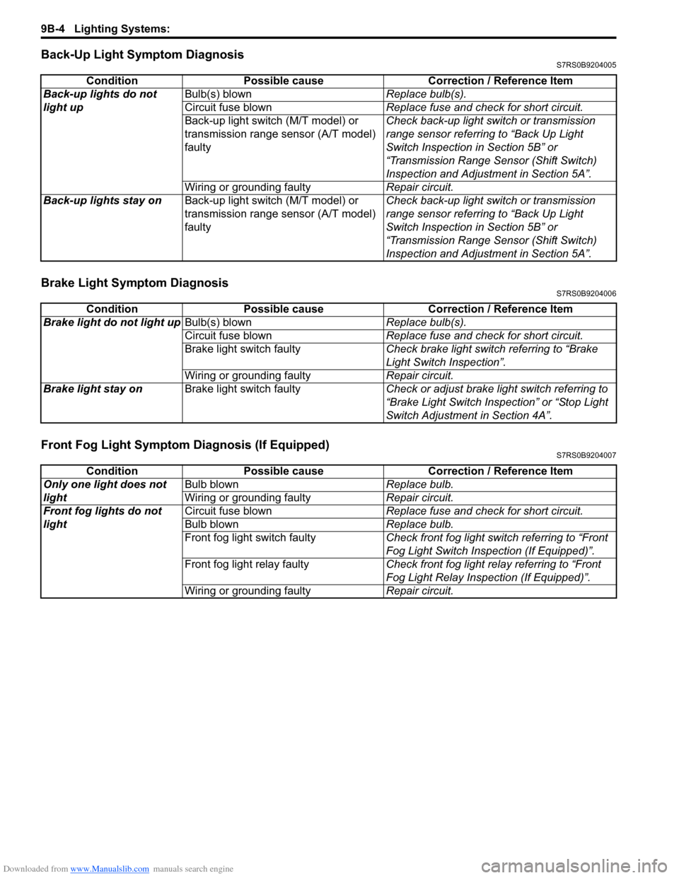
Back-Up Light Symptom DiagnosisS7RS0B9204005
Brake Light Symptom DiagnosisS7RS0B9204006
Front Fog Light Symptom Diagnosis (If Equipped)S7RS0B9204007
ConditionPossible cause Correction / Reference Item
Back-up lights do not
light up Bulb(s) blown
Replace bulb(s).
Circuit fuse blown Replace fuse and check for short circuit.
Back-up light switch (M/T model) or
transmission range sensor (A/T model)
faulty Check back-up light switch or transmission
range sensor referring to “Back Up Light
Switch Inspection in Section 5B” or
“Transmission Range Sensor (Shift Switch)
Inspection and Adjustment in Section 5A”.
Wiring or grounding faulty Repair circuit.
Back-up lights stay on Back-up light switch (M/T model) or
transmission range sensor (A/T model)
faulty Check back-up light switch or transmission
range sensor referring to “Back Up Light
Switch Inspection in Section 5B” or
“Transmission Range Sensor (Shift Switch)
Inspection and Adjustment in Section 5A”.
Condition
Possible cause Correction / Reference Item
Brake light do not light up Bulb(s) blown Replace bulb(s).
Circuit fuse blown Replace fuse and check for short circuit.
Brake light switch faulty Check brake light switch referring to “Brake
Light Switch Inspection”.
Wiring or grounding faulty Repair circuit.
Brake light stay on Brake light switch faulty Check or adjust brake light switch referring to
“Brake Light Switch Inspection” or “Stop Light
Switch Adjustment in Section 4A”.
ConditionPossible cause Correction / Reference Item
Only one light does not
light Bulb blown
Replace bulb.
Wiring or grounding faulty Repair circuit.
Front fog lights do not
light Circuit fuse blown
Replace fuse and check for short circuit.
Bulb blown Replace bulb.
Front fog light switch faulty Check front fog light switch referring to “Front
Fog Light Switch Inspection (If Equipped)”.
Front fog light relay faulty Check front fog light relay referring to “Front
Fog Light Relay Inspection (If Equipped)”.
Wiring or grounding faulty Repair circuit.
Page 1287 of 1496
Downloaded from www.Manualslib.com manuals search engine Lighting Systems: 9B-5
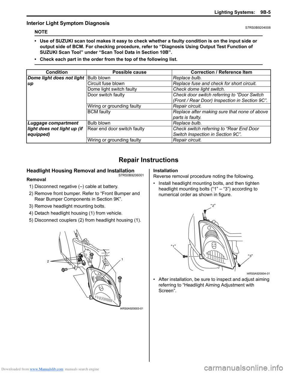
Interior Light Symptom DiagnosisS7RS0B9204008
NOTE
• Use of SUZUKI scan tool makes it easy to check whether a faulty condition is on the input side or
output side of BCM. For checking procedure, re fer to “Diagnosis Using Output Test Function of
SUZUKI Scan Tool” under “Scan Tool Data in Section 10B”.
• Check each part in the order from the top of the following list.
Repair Instructions
Headlight Housing Removal and InstallationS7RS0B9206001
Removal 1) Disconnect negative (–) cable at battery.
2) Remove front bumper. Refer to “Front Bumper and Rear Bumper Componen ts in Section 9K”.
3) Remove headlight mounting bolts.
4) Detach headlight housing (1) from vehicle.
5) Disconnect couplers (2) from headlight housing (1). Installation
Reverse removal procedure noting the following.
• Install headlight mounting bolts, and then tighten
headlight mounting bolts (“1” – “3”) according to
numerical order as shown in figure.
• After installation, be sure to inspect and adjust aiming referring to “Headlight Aiming Adjustment with
Screen”.
Condition Possible cause Correction / Reference Item
Dome light does not light
up Bulb blown
Replace bulb.
Circuit fuse blown Replace fuse and check for short circuit.
Dome light switch faulty Check dome light switch.
Door switch faulty Check door switch referring to “Door Switch
(Front / Rear Door) Inspection in Section 9C”.
Wiring or grounding faulty Repair circuit.
BCM faulty Replace after making sure that none of above
parts is faulty.
Luggage compartment
light does not light up (if
equipped) Bulb blown
Replace bulb.
Rear end door switch faulty Check switch referring to “Rear End Door
Switch Inspection in Section 9C”.
Wiring or grounding faulty Repair circuit.
2 1
I4RS0A920003-01
2
1 3
I4RS0A920004-01
Page 1301 of 1496
Downloaded from www.Manualslib.com manuals search engine Instrumentation / Driver Info. / Horn: 9C-6
Component Location
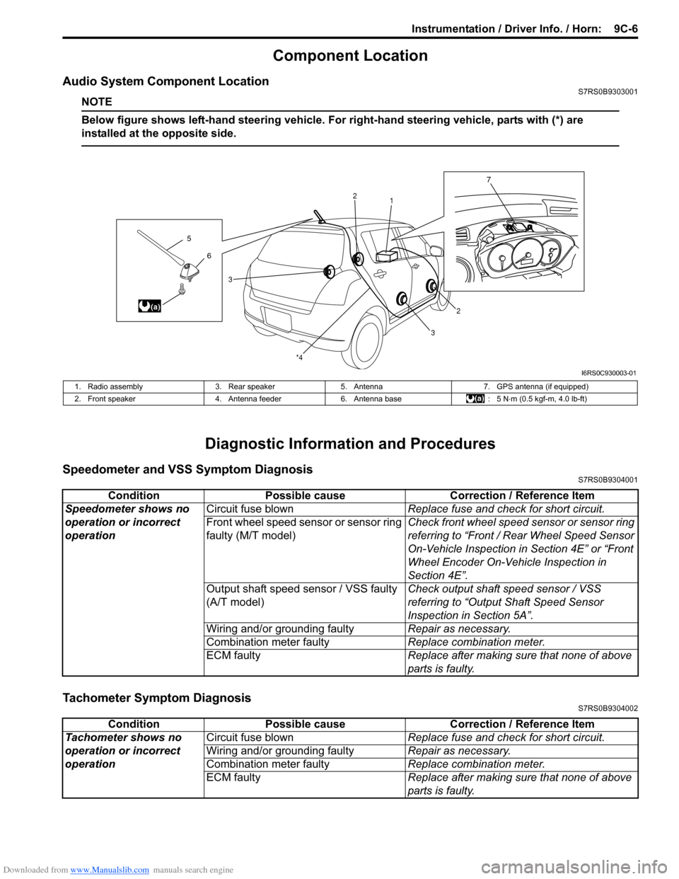
Audio System Component LocationS7RS0B9303001
NOTE
Below figure shows left-hand steering vehicle. For right-hand steering vehicle, parts with (*) are
installed at the opposite side.
Diagnostic Information and Procedures
Speedometer and VSS Symptom DiagnosisS7RS0B9304001
Tachometer Symptom DiagnosisS7RS0B9304002
6
5
(a)
7
1
2
2
3
3
*4
I6RS0C930003-01
1. Radio assembly
3. Rear speaker5. Antenna 7. GPS antenna (if equipped)
2. Front speaker 4. Antenna feeder6. Antenna base : 5 N⋅m (0.5 kgf-m, 4.0 lb-ft)
Condition Possible cause Correction / Reference Item
Speedometer shows no
operation or incorrect
operation Circuit fuse blown
Replace fuse and check for short circuit.
Front wheel speed sensor or sensor ring
faulty (M/T model) Check front wheel speed sensor or sensor ring
referring to “Front / Rear Wheel Speed Sensor
On-Vehicle Inspection in
Section 4E” or “Front
Wheel Encoder On-Vehicle Inspection in
Section 4E”.
Output shaft speed sensor / VSS faulty
(A/T model) Check output shaft
speed sensor / VSS
referring to “Output Shaft Speed Sensor
Inspection in Section 5A”.
Wiring and/or grounding faulty Repair as necessary.
Combination meter faulty Replace combination meter.
ECM faulty Replace after making sure that none of above
parts is faulty.
ConditionPossible cause Correction / Reference Item
Tachometer shows no
operation or incorrect
operation Circuit fuse blown
Replace fuse and check for short circuit.
Wiring and/or grounding faulty Repair as necessary.
Combination meter faulty Replace combination meter.
ECM faulty Replace after making sure that none of above
parts is faulty.
Page 1302 of 1496
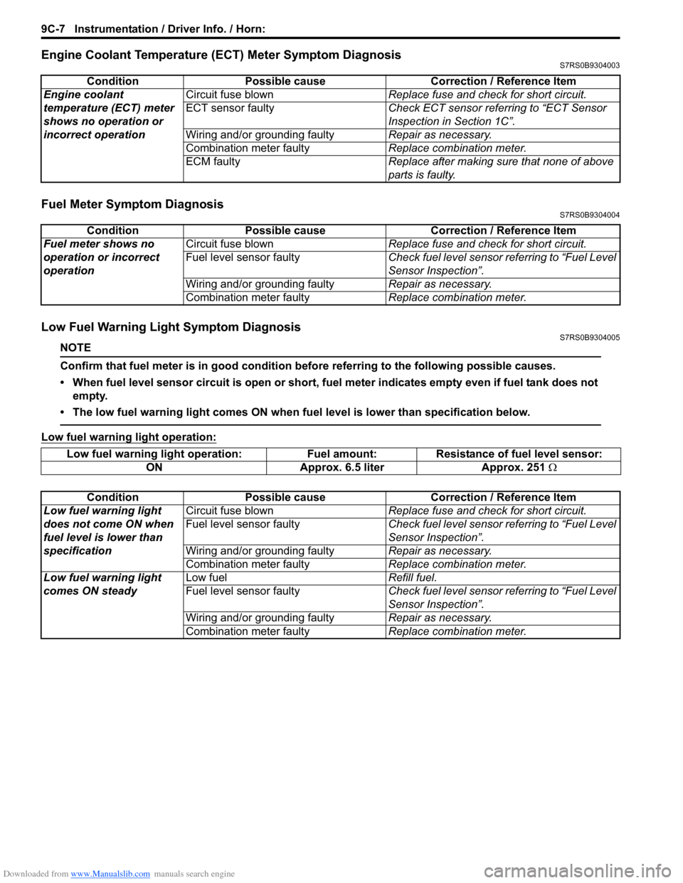
Downloaded from www.Manualslib.com manuals search engine 9C-7 Instrumentation / Driver Info. / Horn:
Engine Coolant Temperature (ECT) Meter Symptom DiagnosisS7RS0B9304003
Fuel Meter Symptom DiagnosisS7RS0B9304004
Low Fuel Warning Light Symptom DiagnosisS7RS0B9304005
NOTE
Confirm that fuel meter is in good condition before referring to the following possible causes.
• When fuel level sensor circuit is open or short, fuel meter indicates empty even if fuel tank does not empty.
• The low fuel warning light comes ON when fu el level is lower than specification below.
Low fuel warning light operation:
ConditionPossible cause Correction / Reference Item
Engine coolant
temperature (ECT) meter
shows no operation or
incorrect operation Circuit fuse blown
Replace fuse and check for short circuit.
ECT sensor faulty Check ECT sensor referring to “ECT Sensor
Inspection in Section 1C”.
Wiring and/or grounding faulty Repair as necessary.
Combination meter faulty Replace combination meter.
ECM faulty Replace after making sure that none of above
parts is faulty.
ConditionPossible cause Correction / Reference Item
Fuel meter shows no
operation or incorrect
operation Circuit fuse blown
Replace fuse and check for short circuit.
Fuel level sensor faulty Check fuel level sensor referring to “Fuel Level
Sensor Inspection”.
Wiring and/or grounding faulty Repair as necessary.
Combination meter faulty Replace combination meter.
Low fuel warning light operation: Fuel amount: Resistance of fuel level sensor:
ON Approx. 6.5 liter Approx. 251 Ω
Condition Possible cause Correction / Reference Item
Low fuel warning light
does not come ON when
fuel level is lower than
specification Circuit fuse blown
Replace fuse and check for short circuit.
Fuel level sensor faulty Check fuel level sensor referring to “Fuel Level
Sensor Inspection”.
Wiring and/or grounding faulty Repair as necessary.
Combination meter faulty Replace combination meter.
Low fuel warning light
comes ON steady Low fuel
Refill fuel.
Fuel level sensor faulty Check fuel level sensor referring to “Fuel Level
Sensor Inspection”.
Wiring and/or grounding faulty Repair as necessary.
Combination meter faulty Replace combination meter.