Cmp SUZUKI SWIFT 2007 2.G Service Owner's Guide
[x] Cancel search | Manufacturer: SUZUKI, Model Year: 2007, Model line: SWIFT, Model: SUZUKI SWIFT 2007 2.GPages: 1496, PDF Size: 34.44 MB
Page 397 of 1496
Downloaded from www.Manualslib.com manuals search engine Ignition System: 1H-5
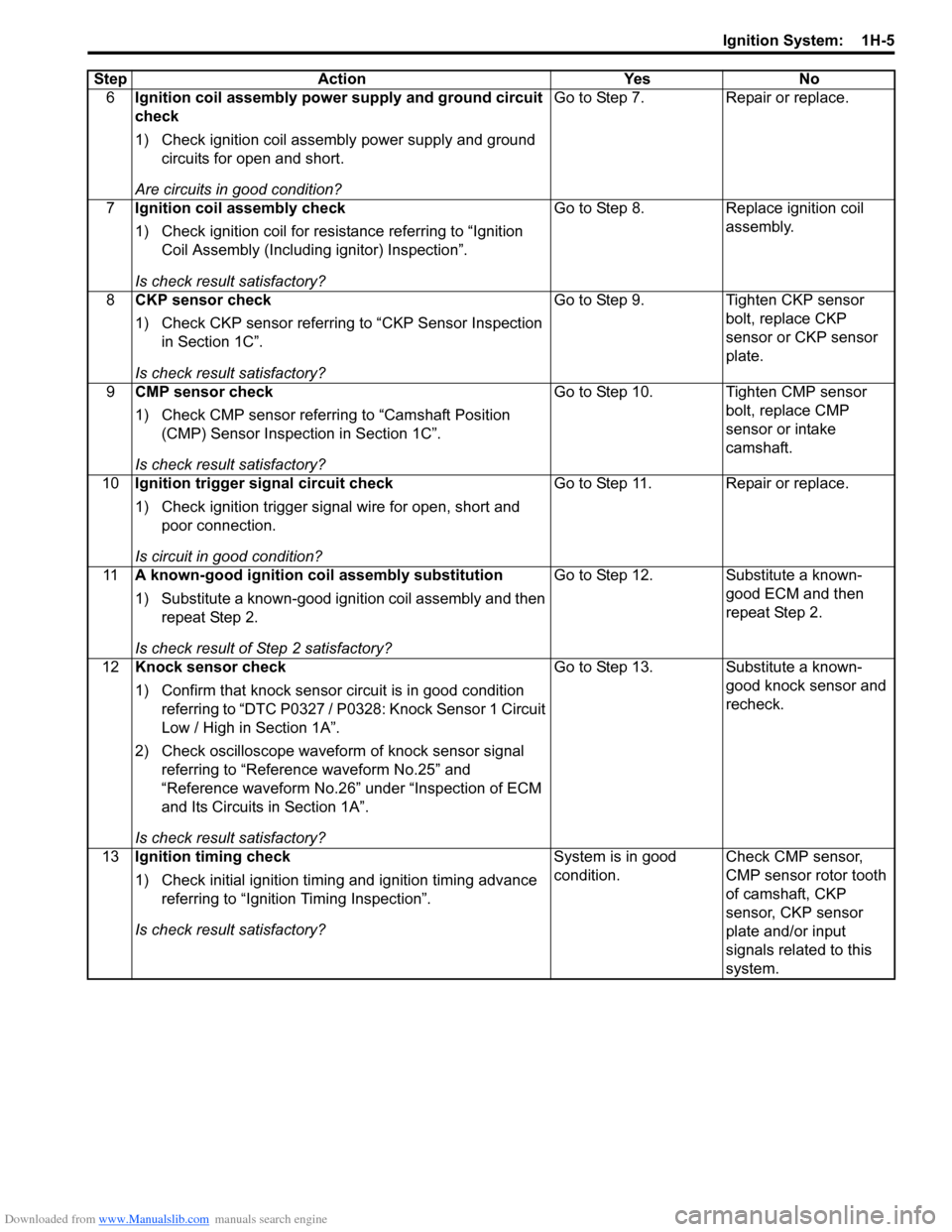
6Ignition coil assembly power supply and ground circuit
check
1) Check ignition coil assembly power supply and ground
circuits for open and short.
Are circuits in good condition? Go to Step 7.
Repair or replace.
7 Ignition coil assembly check
1) Check ignition coil for resistance referring to “Ignition
Coil Assembly (Including ignitor) Inspection”.
Is check result satisfactory? Go to Step 8.
Replace ignition coil
assembly.
8 CKP sensor check
1) Check CKP sensor referring to “CKP Sensor Inspection
in Section 1C”.
Is check result satisfactory? Go to Step 9.
Tighten CKP sensor
bolt, replace CKP
sensor or CKP sensor
plate.
9 CMP sensor check
1) Check CMP sensor referring to “Camshaft Position
(CMP) Sensor Inspection in Section 1C”.
Is check result satisfactory? Go to Step 10. Tighten CMP sensor
bolt, replace CMP
sensor or intake
camshaft.
10 Ignition trigger signal circuit check
1) Check ignition trigger signal wire for open, short and
poor connection.
Is circuit in good condition? Go to Step 11. Repair or replace.
11 A known-good ignition coil assembly substitution
1) Substitute a known-good ignition coil assembly and then
repeat Step 2.
Is check result of Step 2 satisfactory? Go to Step 12. Substitute a known-
good ECM and then
repeat Step 2.
12 Knock sensor check
1) Confirm that knock sensor circuit is in good condition
referring to “DTC P0327 / P0328: Knock Sensor 1 Circuit
Low / High in Section 1A”.
2) Check oscilloscope waveform of knock sensor signal
referring to “Reference waveform No.25” and
“Reference waveform No.26” under “Inspection of ECM
and Its Circuits in Section 1A”.
Is check result satisfactory? Go to Step 13. Substitute a known-
good knock sensor and
recheck.
13 Ignition timing check
1) Check initial ignition timing and ignition timing advance
referring to “Ignition Timing Inspection”.
Is check result satisfactory? System is in good
condition.
Check CMP sensor,
CMP sensor rotor tooth
of camshaft, CKP
sensor, CKP sensor
plate and/or input
signals related to this
system.
Step
Action YesNo
Page 401 of 1496
Downloaded from www.Manualslib.com manuals search engine Ignition System: 1H-9
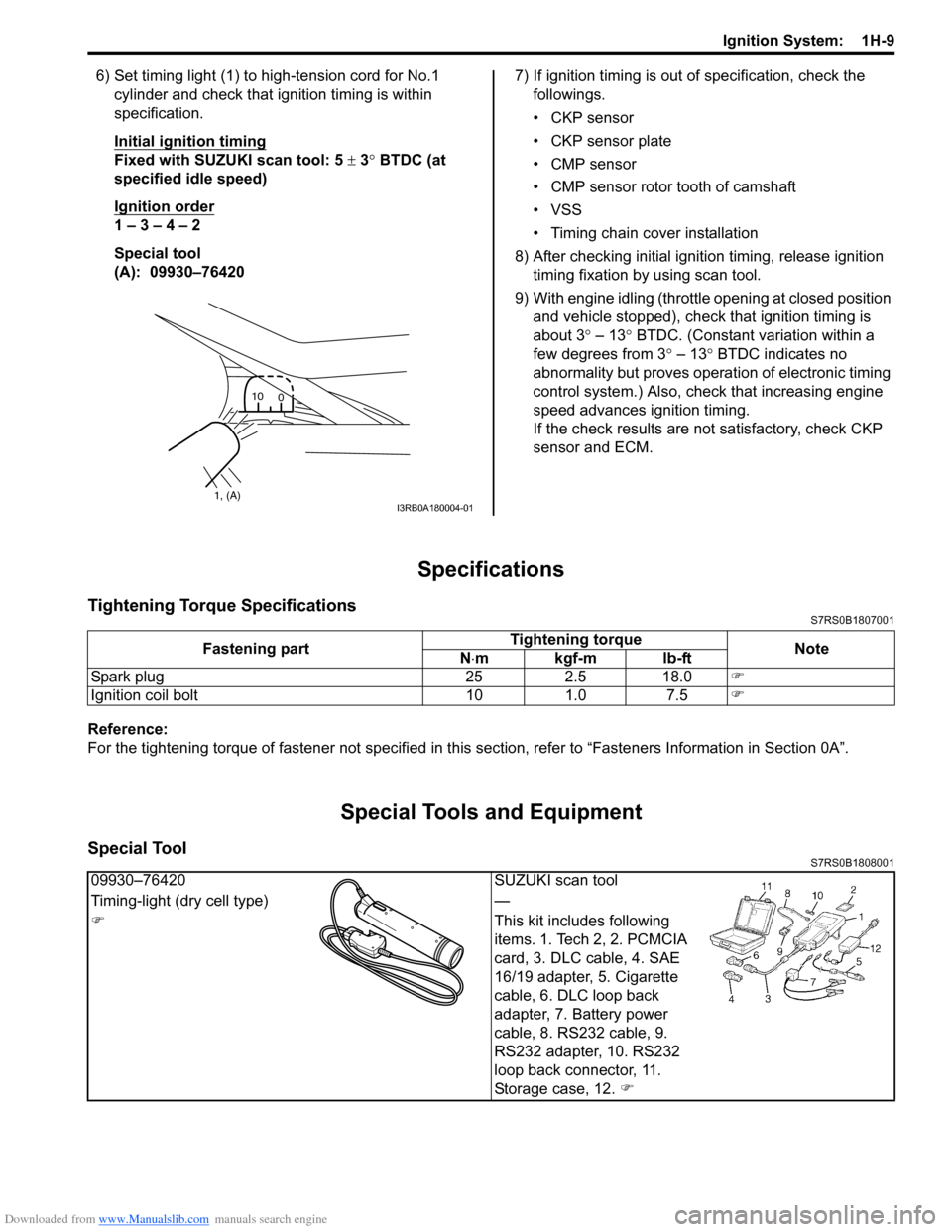
6) Set timing light (1) to high-tension cord for No.1 cylinder and check that ignition timing is within
specification.
Initial ignition timing
Fixed with SUZUKI scan tool: 5 ± 3° BTDC (at
specified idle speed)
Ignition order
1 – 3 – 4 – 2
Special tool
(A): 09930–76420 7) If ignition timing is out
of specification, check the
followings.
• CKP sensor
• CKP sensor plate
• CMP sensor
• CMP sensor rotor tooth of camshaft
• VSS
• Timing chain cover installation
8) After checking initial igniti on timing, release ignition
timing fixation by using scan tool.
9) With engine idling (throttl e opening at closed position
and vehicle stopped), check that ignition timing is
about 3 ° – 13° BTDC. (Constant variation within a
few degrees from 3 ° – 13° BTDC indicates no
abnormality but proves operation of electronic timing
control system.) Also, check that increasing engine
speed advances ignition timing.
If the check results are not satisfactory, check CKP
sensor and ECM.
Specifications
Tightening Torque SpecificationsS7RS0B1807001
Reference:
For the tightening torque of fastener not specified in this section, refer to “Fasteners Information in Section 0A”.
Special Tools and Equipment
Special ToolS7RS0B1808001
1, (A)10
0I3RB0A180004-01
Fastening part Tightening torque
Note
N ⋅mkgf-mlb-ft
Spark plug 25 2.5 18.0 �)
Ignition coil bolt 10 1.0 7.5 �)
09930–76420SUZUKI scan tool
Timing-light (dry cell type) —
�) This kit includes following
items. 1. Tech 2, 2. PCMCIA
card, 3. DLC cable, 4. SAE
16/19 adapter, 5. Cigarette
cable, 6. DLC loop back
adapter, 7. Battery power
cable, 8. RS232 cable, 9.
RS232 adapter, 10. RS232
loop back connector, 11.
Storage case, 12. �)
Page 1182 of 1496

Downloaded from www.Manualslib.com manuals search engine 9A-11 Wiring Systems:
C: Engine harnessNo./Color Connective position No./Color Connective positionC01/GRY IAC valve C22/- Generator #2
C02/GRY IG Coil #1 C23/BLK Starting motor #1
C03/GRY IG Coil #2 C24/- Starting motor #2
C04/GRY Fuel injector #1 C25/GR Y VSS (Vehicle speed sensor)
C05/GRY Fuel injector #2 C26/GRY Knock sensor
C06/GRY Fuel injector #3 C27/BLU (A/
T) Input shaft speed sensor
C07/GRY Fuel injector #4 C28/GRY
(A/T) Trans axle range sensor
C08/BLK or GRY CMP sensor C29/GRY
(A/T) Shift solenoid
C09/BLK ECT sensor C30/BLK
(M/T) Back-up light switch
C10/GRY EGR stepper motor C31/- Main fuse box C11/BLK Throttle position sensor C32/GRY
(IF EQPD) Current sensor
C12/BLK MAP sensor C33/- Main fuse box
C13/BLK MAF sensor C34/N (A/T) TCM
C14/BLK EVAP canister purge valve C35/N (A/T) TCM
C15/GRY Heated oxygen sensor #1 C36/N Main harness (To E24)
C16/GRN Heated oxygen sensor #2 C37/GRY ECM C17/BLK A/C compressor C38/- Weld splice C18/N Oil pressure switch C39/- Weld splice
C19/BLU VVT solenoid C40/- Weld splice
C20/GRY CKP sensor C41/- Weld splice
C21/GRY or BLK Generator #1
Page 1184 of 1496

Downloaded from www.Manualslib.com manuals search engine 9A-13 Wiring Systems:
C: Engine harness
D: Oil pressure switch wireNo./Color Connective position No./Color Connective position
C02/GRY IG Coil #1 C24/- Starting motor #2
C03/GRY IG Coil #2 C23/BLK Starting motor #1
C04/GRY Fuel injector #1 C25/GRY
(A/T) VSS (Vehicle speed sensor)
C05/GRY Fuel injector #2 C26/GRY Knock shaft speed sensor
C06/GRY Fuel injector #3 C27/BLU (A/
T) Input shaft speed sensor
C07/GRY Fuel injector #4 C28/GRY
(A/T) Trans axle range sensor
C08/BLK CMP sensor C29/GRY
(A/T) Shift solenoid
C09/BLK ECT sensor C30/BLK
(M/T) Back-up light switch
C10/GRY EGR stepper motor C31/- Main fuse box C12/BLK MAP sensor C32/GRY Current sensor
C13/BLK MAF sensor C33/- Main fuse box
C14/BLK EVAP canister purge valve C34/N (A/T) TCM
C15/BLK Heated oxygen sensor #1 C35/N (A/T) TCM
C16/GRN Heated oxygen sensor #2 C36/N Main harness (To E24) C17/BLK A/C compressor C37/GRY ECM C18/N Oil pressure switch wire (To D02) C38/- Weld splice
C19/BLU VVT solenoid C39/- Weld splice
C20/GRY CKP sensor C40/- Weld splice C21/BLK Generator #1 C42/BLK Electric throttle body C22/- Generator #2
No./Color Connective position No./ColorConnective position
D01/N Oil pressure switch D02/GRY Engine harness (To C18)
Page 1223 of 1496
Downloaded from www.Manualslib.com manuals search engine Wiring Systems: 9A-52
"E-1"
"E-2"
EGR
stepper motor
PPL
P
"A-6"
AB
AB
CD
CD
ECM
2
3
REDORNGRY/RED
EVAP
thermistor
1
2G09
13
ORN
ORN
E38
G36
BW
Blower
speed
selector
Auto
unit
A/C refrigerant
pressure sensor
E04
C10
BRN/YEL
WHT/REDGRN/RED
6
4312
5
CKP
sensor CMP
sensor VSS
TCM
C37
BLK
3
155830
C25
21
3CDE12CDE23 3
1
CDE31
1 2
3
C08
C20
C37
18 19
4320
219
PNK
RED/YEL
E2354
55
C36
E2410
1
2
3
19
4
RED/WHT
49
BLK/RED
BLK
C012
1 3
IAC
valve
BLU/WHT
GRN/ORN
WHT/BLK
57
4
WHT/BLK
BLK/RED
BLK/ORNBLK/ORNBLK/ORNBLK/ORN
C40Weld splice
BLK/ORNBLK/ORN
C38Weld splice
BLK/REDBLK/RED
BLK/REDBLK/RED
M13A engine M/T, M15A engine M/T
A/T
M13A engine
M15A engine
M16A engine
ABCDE
Manual A/C
Auto A/C
I7RS0B910941-01
Page 1267 of 1496
Downloaded from www.Manualslib.com manuals search engine Wiring Systems: 9A-96
YEL
ABS
Cont.M
L38
LT GRN/BLKLT GRN
LT GRN/BLKLT GRN
L02
E451011
Wheel speed
sensor(RL)
BRN
YELBRN
13
12
L14
Wheel speed
sensor(RR)
WHT/BLK
E05
Wheel speed sensor(FR)
WHTRED
E25
Wheel speed sensor(FL)
RED/BLK
E03
2 12 12 121
5
DLC
PPL/WHT
PPL/WHT
A
A
E38
G36
5
E42
D
J/C
G16
PPL/WHT
E
59E46
BCM
BCMPPL/WHT
WHT/RED
G20 G37
PW
WHT/BLKRED/BLK
RBWB
"A-8"
11
BLK
BLK
A
A
J/C
G15
4
E24
C3615
BLK/ORN
3
BLK/ORN
9
BLK
A
B
B
J/C
G17
15A RADIO
40
G335
WHT/RED
J/B
BLK/ORN
14
6
716
14
E43
J/C
J/C
(CAN) IF EQPD
16
15 24 25 22 21 18 19
I7RS0B910934-01
Page 1269 of 1496
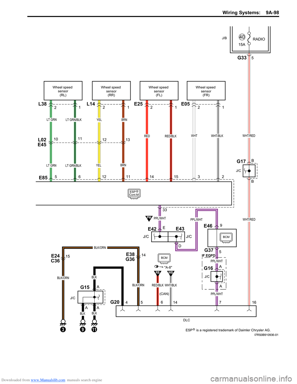
Downloaded from www.Manualslib.com manuals search engine Wiring Systems: 9A-98
YEL
ESP
Cont.M
L38
LT GRN/BLKLT GRN
LT GRN/BLKLT GRN
L02
E4510
5 6 12 11 14 15 3 211
Wheel speed sensor(RL)
BRN
YELBRN
13
12
L14
Wheel speed
sensor(RR)
WHT/BLK
E05
Wheel speed sensor(FR)
WHTRED
E25
Wheel speed sensor(FL)
RED/BLK
E85
2 12 12 121
33
DLC
PPL/WHT
PPL/WHT
A
A
E38
G36
5
E42
D
J/C
G16
PPL/WHT
E
59E46
BCM
BCMPPL/WHT
WHT/RED
G20 G37
PW
WHT/BLKRED/BLK
RBWB
"A-8"
11
BLK
BLK
A
A
J/C
G15
4
E24
C3615
BLK/ORN
3
BLK/ORN
9
BLK
A
B
B
J/C
G17
15A RADIO
40
G335
WHT/RED
J/B
BLK/ORN
14
6
716
14
E43
J/C
J/C
(CAN) IF EQPD
R
RESP is a registered trademark of Daimler Chrysler AG.I7RS0B910936-01
Page 1416 of 1496
Downloaded from www.Manualslib.com manuals search engine 10B-13 Body Electrical Control System:
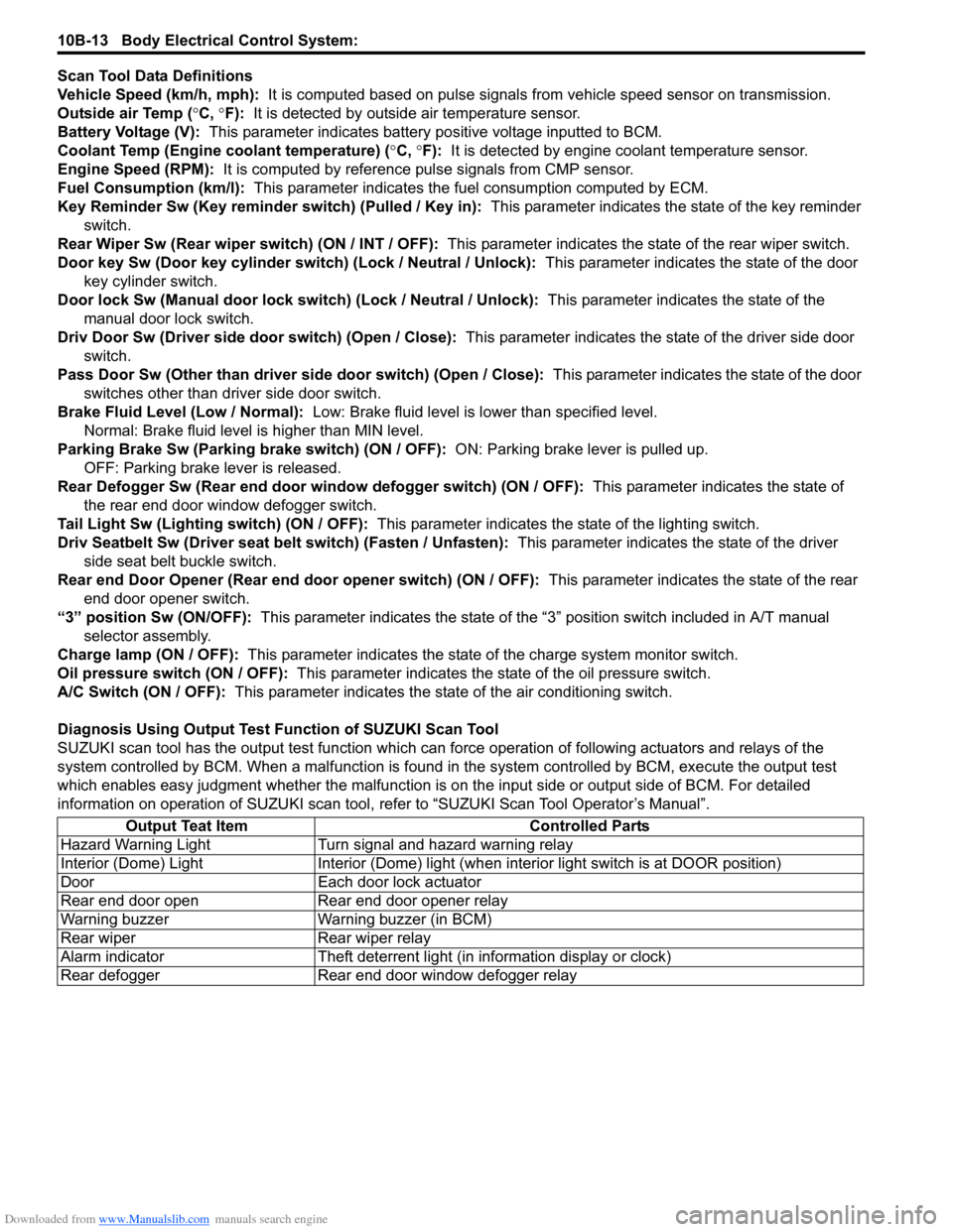
Scan Tool Data Definitions
Vehicle Speed (km/h, mph): It is computed based on pulse signals from vehicle speed sensor on transmission.
Outside air Temp ( °C, °F): It is detected by outside air temperature sensor.
Battery Voltage (V): This parameter indicates battery po sitive voltage inputted to BCM.
Coolant Temp (Engine coolant temperature) ( °C, °F): It is detected by engine coolant temperature sensor.
Engine Speed (RPM): It is computed by reference pulse signals from CMP sensor.
Fuel Consumption (km/l): This parameter indicates the fuel consumption computed by ECM.
Key Reminder Sw (Key reminder switch) (Pulled / Key in): This parameter indicates the state of the key reminder
switch.
Rear Wiper Sw (Rear wiper switch) (ON / INT / OFF): This parameter indicates the state of the rear wiper switch.
Door key Sw (Door key cylinder switch) (Lock / Neutral / Unlock): This parameter indicates the state of the door
key cylinder switch.
Door lock Sw (Manual door lock switch) (Lock / Neutral / Unlock): This parameter indicates the state of the
manual door lock switch.
Driv Door Sw (Driver side d oor switch) (Open / Close): This parameter indicates the state of the driver side door
switch.
Pass Door Sw (Other than driver side door switch) (Open / Close): This parameter indicates the state of the door
switches other than driver side door switch.
Brake Fluid Level (Low / Normal): Low: Brake fluid level is lower than specified level.
Normal: Brake fluid level is higher than MIN level.
Parking Brake Sw (Parking brake switch) (ON / OFF): ON: Parking brake lever is pulled up.
OFF: Parking brake lever is released.
Rear Defogger Sw (Rear end door window defogger switch) (ON / OFF): This parameter indicates the state of
the rear end door window defogger switch.
Tail Light Sw (Lighting switch) (ON / OFF): This parameter indicates the state of the lighting switch.
Driv Seatbelt Sw (Driver seat belt switch) (Fasten / Unfasten): This parameter indicates the state of the driver
side seat belt buckle switch.
Rear end Door Opener (Rear end door opener switch) (ON / OFF): This parameter indicates the state of the rear
end door opener switch.
“3” position Sw (ON/OFF): This parameter indicates the state of the “3 ” position switch included in A/T manual
selector assembly.
Charge lamp (ON / OFF): This parameter indicates the state of the charge system monitor switch.
Oil pressure switch (ON / OFF): This parameter indicates the state of the oil pressure switch.
A/C Switch (ON / OFF): This parameter indicates the state of the air conditioning switch.
Diagnosis Using Output Test Function of SUZUKI Scan Tool
SUZUKI scan tool has the output test function which can force operation of following actuators and relays of the
system controlled by BCM. When a malf unction is found in the system controlled by BCM, execute the output test
which enables easy judgment whether the malfunction is on the input side or output side of BCM. For detailed
information on operation of SUZUKI scan tool, refer to “SUZUKI Scan Tool Operator’s Manual”.
Output Teat Item Controlled Parts
Hazard Warning Light Turn signal and hazard warning relay
Interior (Dome) Light Interior (Dome) light (wh en interior light switch is at DOOR position)
Door Each door lock actuator
Rear end door open Rear end door opener relay
Warning buzzer Warning buzzer (in BCM)
Rear wiper Rear wiper relay
Alarm indicator Theft deterrent light (in information display or clock)
Rear defogger Rear end door window defogger relay