Dtc table SUZUKI SWIFT 2007 2.G Service Owner's Guide
[x] Cancel search | Manufacturer: SUZUKI, Model Year: 2007, Model line: SWIFT, Model: SUZUKI SWIFT 2007 2.GPages: 1496, PDF Size: 34.44 MB
Page 894 of 1496
Downloaded from www.Manualslib.com manuals search engine 6C-12 Power Assisted Steering System:
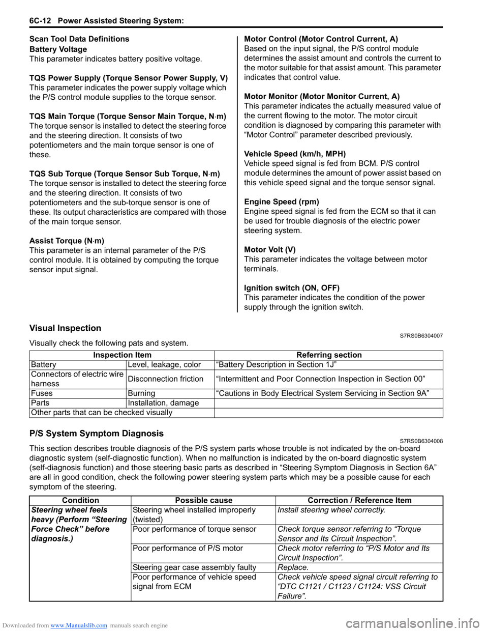
Scan Tool Data Definitions
Battery Voltage
This parameter indicates battery positive voltage.
TQS Power Supply (Torque Sensor Power Supply, V)
This parameter indicates the power supply voltage which
the P/S control module supplies to the torque sensor.
TQS Main Torque (Torque Sensor Main Torque, N ⋅m)
The torque sensor is installed to detect the steering force
and the steering directio n. It consists of two
potentiometers and the main torque sensor is one of
these.
TQS Sub Torque (Torque Sensor Sub Torque, N ⋅m)
The torque sensor is installed to detect the steering force
and the steering directio n. It consists of two
potentiometers and the sub-torque sensor is one of
these. Its output characteristics are compared with those
of the main torque sensor.
Assist Torque (N ⋅m)
This parameter is an internal parameter of the P/S
control module. It is obtained by computing the torque
sensor input signal. Motor Control (Motor Control Current, A)
Based on the input signal, the P/S control module
determines the assist amount
and controls the current to
the motor suitable for that a ssist amount. This parameter
indicates that control value.
Motor Monitor (Motor Monitor Current, A)
This parameter indicates the actually measured value of
the current flowing to the motor. The motor circuit
condition is diagnosed by co mparing this parameter with
“Motor Control” parameter described previously.
Vehicle Speed (km/h, MPH)
Vehicle speed signal is fed from BCM. P/S control
module determines the amount of power assist based on
this vehicle speed signal and the torque sensor signal.
Engine Speed (rpm)
Engine speed signal is fed from the ECM so that it can
be used for trouble diagnos is of the electric power
steering system.
Motor Volt (V)
This parameter indicates the voltage between motor
terminals.
Ignition switch (ON, OFF)
This parameter indicates the condition of the power
supply through the ignition switch.
Visual InspectionS7RS0B6304007
Visually check the following pats and system.
P/S System Symptom DiagnosisS7RS0B6304008
This section describes trouble diagnosis of the P/S system parts whose trouble is not indicated by the on-board
diagnostic system (self-diagnostic functi on). When no malfunction is indicated by the on-board diagnostic system
(self-diagnosis function) and those stee ring basic parts as described in “Steering Symptom Diagnosis in Section 6A”
are all in good condition, check the following power steer ing system parts which may be a possible cause for each
symptom of the steering. Inspection Item Referring section
Battery Level, leakage, color “Batte ry Description in Section 1J”
Connectors of electric wire
harness Disconnection friction “Intermittent and Poor
Connection Inspection in Section 00”
Fuses Burning “Cautions in Body Electric al System Servicing in Section 9A”
Parts Installation, damage
Other parts that can be checked visually
Condition Possible cause Correction / Reference Item
Steering wheel feels
heavy (Perform “Steering
Force Check” before
diagnosis.) Steering wheel installed improperly
(twisted)
Install steering wheel correctly.
Poor performance of torque sensor Check torque sensor referring to “Torque
Sensor and Its Circuit Inspection”.
Poor performance of P/S motor Check motor referring to “P/S Motor and Its
Circuit Inspection”.
Steering gear case assembly faulty Replace.
Poor performance of vehicle speed
signal from ECM Check vehicle speed signal circuit referring to
“DTC C1121 / C1123 / C1124: VSS Circuit
Failure”.
Page 934 of 1496

Downloaded from www.Manualslib.com manuals search engine 7-ii Table of Contents
Recommended Service Material ....................... 7B-33
Special Tool ...................................................... 7B-33
Automatic Type .................... .................................7B-34
Precautions.........................................................7B-34 A/C System Caution .......................................... 7B-34
Precautions in Diagnosing Trouble ................... 7B-34
Precautions on Servicing A/C System .............. 7B-34
General Description .......... .................................7B-34
Auto A/C System Descript ion ............................ 7B-34
HVAC Control Module Operation Description ... 7B-36
Refrigerant Type Identifica tion .......................... 7B-36
Sub-Cool A/C System Description .................... 7B-36
A/C Operation Description ................................ 7B-36
On-Board Diagnostic System Description ......... 7B-37
Schematic and Routing Diagram ......................7B-37 Major Components of A/C System .................... 7B-37
A/C System Wiring Diagra m ............................. 7B-38
Diagnostic Information and Procedures ..........7B-39 A/C System Symptom Diagnosis ...................... 7B-39
Abnormal Noise Sympto m Diagnosis of A/C
System ............................................................ 7B-42
DTC Check........................................................ 7B-42
DTC Clearance ................................................. 7B-43
DTC Table ......................................................... 7B-44
Fail-Safe Table ................. ................................. 7B-45
Scan Tool Data ................................................. 7B-46
Air Conditioning System Check......................... 7B-47
Visual Inspection ............................................... 7B-49
DTC B1502: Inside Air Temperature Sensor and/or Its Circuit Malfunction .......................... 7B-49
DTC B1503: A/C Evaporator Air Temperature Sensor and/or Its Circuit Malfunction .............. 7B-50
DTC B1504: Sunload Sensor and/or Its Circuit Malfunction ......... ................................. 7B-52
DTC B1511: Temperature Control Actuator (Position Sensor) and/or Its Circuit
Malfunction ...................................................... 7B-53
DTC B1512: Air flow Control Actuator (Position Sensor) and/or Its Circuit
Malfunction ...................................................... 7B-55
DTC B1513: Temperature Control Actuator and/or Its Circuit Malfunction .......................... 7B-57
DTC B1514: Air Flow Co ntrol Actuator and/or
Its Circuit Malfunction ...................................... 7B-60
DTC B1541: HVAC Control Module Back-Up Power Supply Malfunction .............................. 7B-62
DTC B1546: A/C Refrigerant Pressure Malfunction ...................................................... 7B-63
DTC B1551: Serial Communication Circuit Malfunction ...................................................... 7B-63
DTC B1552: Serial Communication Signal Malfunction ...................................................... 7B-64
DTC B1553: CAN Communication Signal Malfunction ...................................................... 7B-65
DTC B1557: Vehicle Speed Sensor Signal Malfunction ...................................................... 7B-65
DTC B1561: Engine Coolant Temperature Sensor Signal Malfunctio n .............................. 7B-66 DTC B1562: Outside Air Temperature Sensor
Signal Malfunction ........................................... 7B-66
DTC B1563: A/C Refr igerant Pressure
Sensor Signal Malfunction .............................. 7B-66
Inspection of HVAC Control Module and Its Circuit .............................................................. 7B-67
A/C System Performance Inspection ................ 7B-70
A/C System Inspection at ECM ......................... 7B-70
Repair Instructions ............ ................................7B-71
Operation Procedure for Refrigerant Charge .... 7B-71
HVAC Unit Components ................................... 7B-72
HVAC Unit Removal and In stallation ................ 7B-73
Temperature Control Actuator Removal and Installation ....................................................... 7B-73
Temperature Control Actuat or Inspection ......... 7B-73
Air Flow Control Actuator Removal and Installation ....................................................... 7B-74
Air Flow Control Actuator Inspection ................. 7B-74
Air Intake Control Actuator Removal and Installation ....................................................... 7B-75
Air Intake Control Actuator Inspection............... 7B-75
Actuator Linkage Inspection .............................. 7B-76
Blower Motor Controller Removal and Installation ....................................................... 7B-76
Blower Motor Controller Inspection ................... 7B-76
HVAC Control Module Removal and Installation ....................................................... 7B-77
Sunload Sensor Removal and Installation ........ 7B-77
Sunload Sensor Inspection ............................... 7B-77
Outside Air Temperature Sensor Removal and Installation ................................................ 7B-77
Outside Air Temperature Sensor Inspection ..... 7B-77
Inside Air Temperature Sensor Removal and Installation ....................................................... 7B-78
Inside Air Temperature Sens or Inspection ........ 7B-78
Condenser Assembly On-Vehicle Inspection .... 7B-78
Condenser Assembly Removal and Installation ....................................................... 7B-78
Receiver/Dryer Removal and Installation .......... 7B-78
Evaporator Inspection ....................................... 7B-78
Evaporator Temperature Sensor Removal and Installation ................................................ 7B-78
Evaporator Temperature Se nsor Inspection ..... 7B-78
Expansion Valve Removal an d Installation ....... 7B-78
Expansion Valve Inspection .............................. 7B-78
A/C Refrigerant Pressure Sensor and Its Circuit Inspection............................................. 7B-78
A/C Refrigerant Pressu re Sensor Removal
and Installation ................................................ 7B-78
Compressor Relay Inspection .
.......................... 7B-78
Compressor Drive Belt Inspection and Adjustment ...................................................... 7B-78
Compressor Drive Belt Removal and Installation ....................................................... 7B-79
Compressor Assembly Removal and Installation ....................................................... 7B-79
Compressor Assembly Components................. 7B-79
Magnet Clutch Removal and Installation........... 7B-79
Magnet Clutch Inspection.................................. 7B-79
Relief Valve Inspection...................................... 7B-79
Page 992 of 1496
Downloaded from www.Manualslib.com manuals search engine 7B-44 Air Conditioning System: Automatic Type
3) Light over sunload sensor vertically with an incandescent lamp approximately 100 W apart from
about 100 mm (3.94 in.).
NOTE
If sunload sensor is not lighted over with an
incandescent lamp, DTC B1504 is detected
as current DTC even though there is not any
malfunction.
4) Turn ignition switch to ON position.
5) Erase DTC according to instructions displayed on SUZUKI scan tool.
NOTE
To know how to use SUZUKI scan tool, refer
to operator’s manual for SUZUKI scan tool.
6) After completing the clearance, turn ignition switch to OFF position, and then di sconnect SUZUKI scan
tool from DLC.
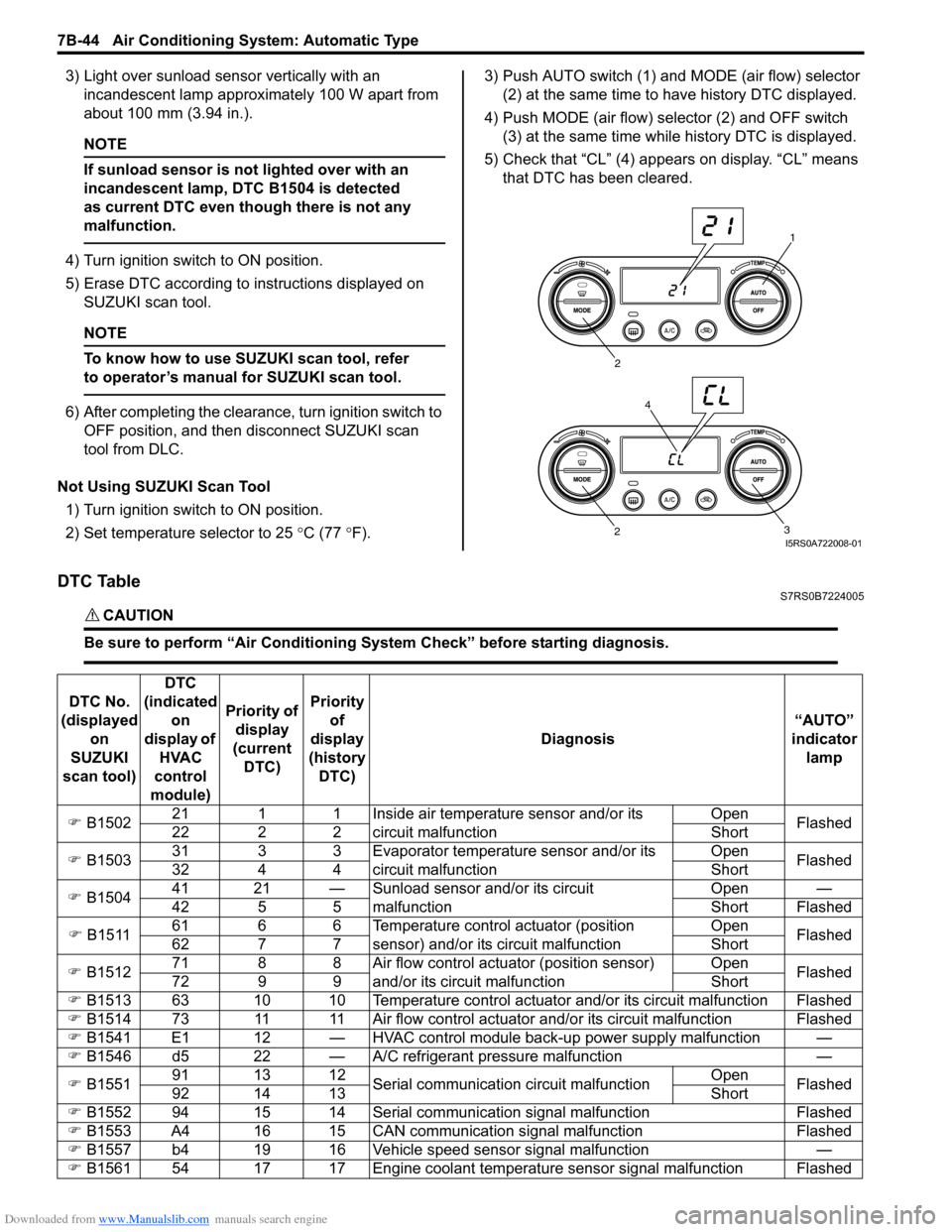
Not Using SUZUKI Scan Tool 1) Turn ignition switch to ON position.
2) Set temperature selector to 25 °C (77 °F). 3) Push AUTO switch (1) and
MODE (air flow) selector
(2) at the same time to have history DTC displayed.
4) Push MODE (air flow) selector (2) and OFF switch (3) at the same time while history DTC is displayed.
5) Check that “CL” (4) appears on display. “CL” means that DTC has been cleared.
DTC TableS7RS0B7224005
CAUTION!
Be sure to perform “Air Conditioning Sy stem Check” before starting diagnosis.
1
2
3
2
4
I5RS0A722008-01
DTC No.
(displayed on
SUZUKI
scan tool) DTC
(indicated on
display of HVAC
control
module) Priority of
display
(current DTC) Priority
of
display
(history DTC) Diagnosis
“AUTO”
indicator lamp
�) B1502 21 1 1 Inside air temperature sensor and/or its
circuit malfunction Open
Flashed
22 2 2 Short
�) B1503 31 3 3 Evaporator temperature sensor and/or its
circuit malfunction Open
Flashed
32 4 4 Short
�) B1504 41 21 — Sunload sensor and/or its circuit
malfunction Open —
42 5 5 Short Flashed
�) B1511 61 6 6 Temperature control actuator (position
sensor) and/or its circuit malfunction Open
Flashed
62 7 7 Short
�) B1512 71 8 8 Air flow control actuator (position sensor)
and/or its circuit malfunction Open
Flashed
72 9 9 Short
�) B1513 63 10 10 Temperature control actuator and/or its circuit malfunction Flashed
�) B1514 73 11 11 Air flow control actuator and/or its circuit malfunction Flashed
�) B1541 E1 12 — HVAC control module back-up power supply malfunction —
�) B1546 d5 22 — A/C refrigerant pressure malfunction —
�) B1551 91 13 12
Serial communication circuit malfunction Open
Flashed
92 14 13 Short
�) B1552 94 15 14 Serial communication signal malfunction Flashed
�) B1553 A4 16 15 CAN communication signal malfunction Flashed
�) B1557 b4 19 16 Vehicle speed sensor signal malfunction —
�) B1561 54 17 17 Engine coolant temperature sensor signal malfunction Flashed
Page 993 of 1496
Downloaded from www.Manualslib.com manuals search engine Air Conditioning System: Automatic Type 7B-45
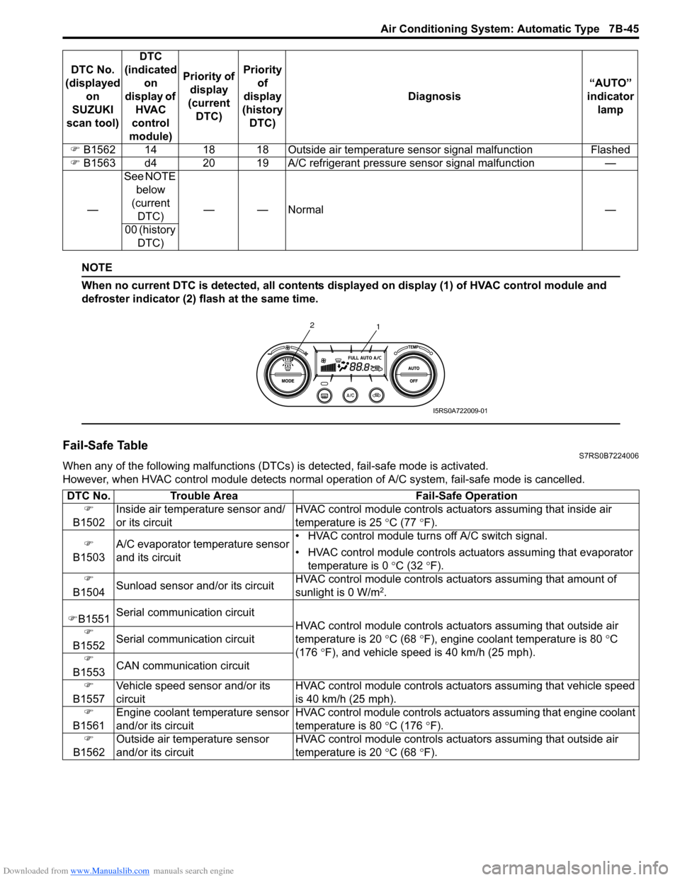
NOTE
When no current DTC is detected, all contents displayed on display (1) of HVAC control module and
defroster indicator (2) flash at the same time.
Fail-Safe TableS7RS0B7224006
When any of the following malfunctions (DTCs) is detected, fail-safe mode is activated.
However, when HVAC control module detects normal ope ration of A/C system, fail-safe mode is cancelled.
�)
B1562 14 18 18 Outside air temperatur e sensor signal malfunction Flashed
�) B1563 d4 20 19 A/C refrigerant pressure sensor signal malfunction —
— See NOTE
below
(current DTC) ——Normal —
00 (history DTC)
DTC No.
(displayed on
SUZUKI
scan tool) DTC
(indicated on
display of HVAC
control
module) Priority of
display
(current DTC) Priority
of
display
(history DTC) Diagnosis
“AUTO”
indicator lamp
1
2
I5RS0A722009-01
DTC No.
Trouble Area Fail-Safe Operation
�)
B1502 Inside air temperature sensor and/
or its circuit HVAC control module controls actu
ators assuming that inside air
temperature is 25 ° C (77 °F).
�)
B1503 A/C evaporator temperature sensor
and its circuit • HVAC control module turn
s off A/C switch signal.
• HVAC control module controls actu ators assuming that evaporator
temperature is 0 ° C (32 °F).
�)
B1504 Sunload sensor and/or its circuit HVAC control module controls actu
ators assuming that amount of
sunlight is 0 W/m
2.
�) B1551 Serial communication circuit
HVAC control module controls actuators assuming that outside air
temperature is 20 ° C (68 °F), engine coolant temperature is 80 °C
(176 °F), and vehicle speed is 40 km/h (25 mph).
�)
B1552 Serial communication circuit
�)
B1553 CAN communication circuit
�)
B1557 Vehicle speed sensor and/or its
circuit HVAC control module controls act
uators assuming that vehicle speed
is 40 km/h (25 mph).
�)
B1561 Engine coolant temperature sensor
and/or its circuit HVAC control module controls act
uators assuming that engine coolant
temperature is 80 ° C (176 °F).
�)
B1562 Outside air temperature sensor
and/or its circuit HVAC control module controls actu
ators assuming that outside air
temperature is 20 ° C (68 °F).
Page 1019 of 1496
Downloaded from www.Manualslib.com manuals search engine Air Conditioning System: Automatic Type 7B-71
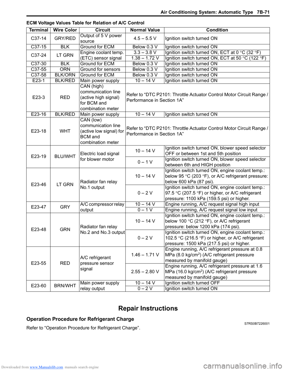
ECM Voltage Values Table for Relation of A/C Control
Repair Instructions
Operation Procedure for Refrigerant ChargeS7RS0B7226001
Refer to “Operation Procedure for Refrigerant Charge”.Terminal Wire Color Circuit Normal Value Condition
C37-14 GRY/RED Output of 5 V power
source 4.5 – 5.5 V Ignition switch turned ON
C37-15 BLK Ground for ECM Below 0.3 V Ignition switch turned ON
C37-24 LT GRN Engine coolant temp.
(ETC) sensor signal 3.3 – 3.8 V Ignition switch turned ON, ECT at 0
°C (32 ° F)
1.38 – 1.72 V Ignition switch turned ON, ECT at 50 °C (122 °F)
C37-30 BLK Ground for ECM Below 0.3 V Ignition switch turned ON
C37-55 ORN Ground for sensors Below 0.3 V Ignition switch turned ON
C37-58 BLK/ORN Ground for ECM Below 0.3 V Ignition switch turned ON E23-1 BLK/RED Main power supply 10 – 14 V Ignition switch turned ON
E23-3 RED CAN (high)
communication line
(active high signal)
for BCM and
combination meterRefer to “DTC P2101: Throttle Actu
ator Control Motor Circuit Range /
Performance in Section 1A”
E23-16 BLK/RED Main power supply 10 – 14 V Ignition switch turned ON
E23-18 WHT CAN (low)
communication line
(active low signal) for
BCM and
combination meterRefer to “DTC P2101: Throttle Actu
ator Control Motor Circuit Range /
Performance in Section 1A”
E23-19 BLU/WHT Electric load signal
for blower motor 10 – 14 V
Ignition switch turned ON, blower speed selector
OFF or between 1st and 5th position
0 – 1 V Ignition switch turned ON, blower speed selector
between 6th and HIGH position
E23-46 LT GRN Radiator fan relay
No.1 output 10 – 14 V
Ignition switch turned ON, engine coolant temp.:
below 95
°C (203 ° F), or A/C refrigerant pressure:
below 600 kPa (87 psi).
0 – 2 V Ignition switch turned ON, engine coolant temp.:
97.5
°C (207.5 °F) or higher, or A/C refrigerant
pressure: 1100 kPa (159.5 psi) or higher.
E23-47 GRY A/C compressor relay
output 10 – 14 V Engine running, A/C request signal high input
0 – 1 V Engine running, A/C request signal low input
E23-48 GRN Radiator fan relay
No.2 and No.3 output 10 – 14 V
Ignition switch turned ON, engine coolant temp.:
below 100
°C (212 °F), or A/C refrigerant
pressure: below 1200 kPa (174 psi).
0 – 2 V Ignition switch turned ON, engine coolant temp.:
102.5
°C (216.5 ° F) or higher, or A/C refrigerant
pressure: 1500 kPa (217.5 psi) or higher.
E23-55 RED A/C refrigerant
pressure sensor
signal 1.46 – 1.71 V
Engine running, A/C refrigerant pressure at 0.8
MPa (8.0 kg/cm
2) (A/C refrigerant pressure
measured by manifold gauge)
2.55 – 2.80 V Engine running, A/C refrigerant pressure at 1.6
MPa (16.0 kg/cm
2) (A/C refrigerant pressure
measured by manifold gauge)
E23-60 BRN/WHT Main power supply
relay output 10 – 14 V Ignition switch turned OFF
0 – 2 V Ignition switch turned ON
Page 1029 of 1496
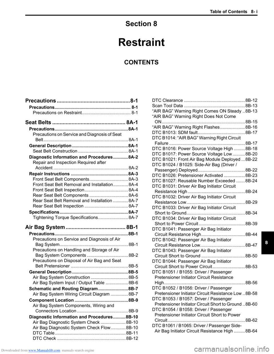
Downloaded from www.Manualslib.com manuals search engine Table of Contents 8- i
8
Section 8
CONTENTS
Restraint
Precautions ................................................. 8-1
Precautions............................................................. 8-1
Precautions on Restraint ....................................... 8-1
Seat Belts .......... ............................... ........ 8A-1
Precautions........................................................... 8A-1
Precautions on Service a nd Diagnosis of Seat
Belt .................................................................... 8A-1
General Description ............................................. 8A-1 Seat Belt Construction ........................................ 8A-1
Diagnostic Information and Procedures ............ 8A-2 Repair and Inspection Required after Accident ............................................................ 8A-2
Repair Instructions .............................................. 8A-3 Front Seat Belt Components ............................... 8A-3
Front Seat Belt Removal and Installation ............ 8A-4
Front Seat Belt Inspection ................................... 8A-4
Rear Seat Belt Components ............................... 8A-6
Rear Seat Belt Removal and Installation ............ 8A-7
Rear Seat Belt Inspection ................................... 8A-7
Specifications ....................................................... 8A-7
Tightening Torque Specifications ........................ 8A-7
Air Bag System ............... ......................... 8B-1
Precautions........................................................... 8B-1
Precautions on Service and Diagnosis of Air Bag System....................................................... 8B-1
Precautions on Handling and Storage of Air Bag System Components . ................................ 8B-2
Precautions on Disposal of Air Bag and Seat
Belt Pretensioner .............................................. 8B-5
General Description ............................................. 8B-5 Air Bag System Construction .............................. 8B-5
Air Bag System Input / Output Table .................. 8B-6
Schematic and Routing Diagram ........................ 8B-7 Air Bag System Wiring Circuit Diagram .............. 8B-7
Component Locatio n ........................................... 8B-9
Air Bag System Components, Wiring and Connectors Location ......................................... 8B-9
Diagnostic Information and Procedures .......... 8B-10 Air Bag Diagnostic System Check .................... 8B-10
Air Bag Diagnostic System Check Flow ............ 8B-10
DTC Table ......................................................... 8B-11
DTC Check ....................................................... 8B-12 DTC Clearance ................................................. 8B-12
Scan Tool Data ................................................. 8B-13
“AIR BAG” Warning Right Comes ON Steady .. 8B-13
“AIR BAG” Warning Right Does Not Come
ON ................................................................... 8B-15
“AIR BAG” Warning Right Flashes .................... 8B-16
DTC B1013: SDM fault...................................... 8B-17
DTC B1014: “AIR BAG” Warning Right Circuit Failure ............................................................. 8B-17
DTC B1016: Power Source Voltage High ......... 8B-18
DTC B1017: Power Source Voltage Low .......... 8B-20
DTC B1021: Front Air Bag Module Deployed ... 8B-22
DTC B1024 / B1025: Side-Air Bag (Driver / Passenger) Deployed...................................... 8B-22
DTC B1026: Pretensioner Activated ................. 8B-23
DTC B1027: Reusable Number Exceeded ....... 8B-24
DTC B1031: Driver Air Bag Initiator Circuit
Resistance High .............................................. 8B-24
DTC B1032: Driver Air Bag Initiator Circuit
Resistance Low ............................................... 8B-29
DTC B1033: Driver Air Bag Initiator Circuit
Short to Ground............................................... 8B-34
DTC B1034: Driver Air Bag Initiator Circuit
Short to Power Circuit .... ................................. 8B-39
DTC B1041: Passenger Air Bag Initiator Circuit Resistance High ................................... 8B-44
DTC B1042: Passenger Air Bag Initiator Circuit Resistance Low.................................... 8B-47
DTC B1043: Passenger Air Bag Initiator Circuit Short to Ground ................................... 8B-50
DTC B1044: Passenger Air Bag Initiator Circuit Short to Power Circ uit .......................... 8B-53
DTC B1051 / B1055: Driver / Passenger Pretensioner Initiator Circuit Resistance
High ................................................................. 8B-56
DTC B1052 / B1056: Driver / Passenger Pretensioner Initiator Circu it Resistance Low .. 8B-58
DTC B1053 / B1057: Driver / Passenger Pretensioner Initiator Circuit Short to Ground .. 8B-60
DTC B1054 / B1058: Driver / Passenger Pretensioner Initiator Circuit Short to Power
Circuit .............................................................. 8B-62
DTC B1061 / B1065: Driver / Passenger Side- Air Bag Initiator Circuit Resistance High ......... 8B-64
Page 1030 of 1496
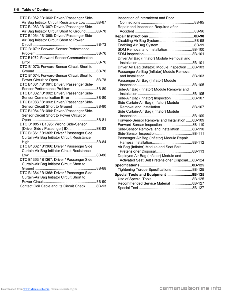
Downloaded from www.Manualslib.com manuals search engine 8-ii Table of Contents
DTC B1062 / B1066: Driver / Passenger Side-Air Bag Initiator Circuit Resistance Low .......... 8B-67
DTC B1063 / B1067: Driver / Passenger Side- Air Bag Initiator Circuit S hort to Ground .......... 8B-70
DTC B1064 / B1068: Driver / Passenger Side- Air Bag Initiator Circu it Short to Power
Circuit .............................................................. 8B-73
DTC B1071: Forward-Sensor Performance Problem ........................................................... 8B-76
DTC B1072: Forward-Sensor Communication Error ................................................................ 8B-76
DTC B1073: Forward-Sensor Circuit Short to Ground ............................................................ 8B-76
DTC B1074: Forward-Sensor Circuit Short to Power Circuit or Open ..................................... 8B-78
DTC B1081 / B1091: Driver / Passenger Side- Sensor Performance Probl em ......................... 8B-80
DTC B1082 / B1092: Driver / Passenger Side- Sensor Communication Erro r .......................... 8B-80
DTC B1083 / B1093: Driver / Passenger Side- Sensor Circuit Short to Ground ....................... 8B-80
DTC B1084 / B1094: Driver / Passenger Side- Sensor Circuit Short to Power Circuit or
Open ............................................................... 8B-81
DTC B1085 / B1095: Wrong Side-Sensor (Driver Side / Passenger) ID ........................... 8B-83
DTC B1361 / B1365: Driver / Passenger Side Curtain-Air Bag Initiator Circuit Resistance
High ................................................................. 8B-84
DTC B1362 / B1366: Driver / Passenger Side Curtain-Air Bag Initiator Circuit Resistance
Low ................................................................. 8B-86
DTC B1363 / B1367: Driver / Passenger Side Curtain-Air Bag Initiator Circuit Short to
Ground ............................................................ 8B-88
DTC B1364 / B1368: Driver / Passenger Side Curtain-Air Bag Initiator Circuit Short to
Power Circuit ................................................... 8B-90
Contact Coil Cable and Its Circuit Check .......... 8B-93 Inspection of Intermittent and Poor
Connections .................................................... 8B-95
Repair and Inspection Required after Accident .......................................................... 8B-96
Repair Instructions ............ ................................8B-98
Disabling Air Bag System.................................. 8B-98
Enabling Air Bag System .................................. 8B-99
SDM Removal and Installation ........................ 8B-100
SDM Inspection ............................................... 8B-101
Driver Air Bag (Inflato r) Module Removal and
Installation ..................................................... 8B-101
Driver Air Bag (Inflator) Module Inspection ..... 8B-103
Passenger Air Bag (Inflator) Module Removal and Installation .............................................. 8B-103
Passenger Air Bag (I nflator) Module
Inspection ...................................................... 8B-105
Side-Air Bag (Inflator) Module Removal and
Installation ..................................................... 8B-105
Side-Air Bag (Inflator) Inspection .................... 8B-107
Side Curtain-Air Bag (Inflator) Module Removal and Installation ............................... 8B-107
Side Curtain-Air Bag (Inflator) Module Inspection ...................................................... 8B-109
Forward-Sensor Removal and Installation ...... 8B-109
Forward-Sensor In spection ............................. 8B-110
Side-Sensor Removal and Installation ............ 8B-110
Side-Sensor Inspection ................................... 8B-111
Passenger Air Bag (Inflator) Module Repair
Harness Installation....................................... 8B-112
Air Bag (Inflator) Module and Seat Belt Pretensioner Disposal ................................... 8B-113
Deployed Air Bag (Inflator) Module and Activated Seat Belt Pretensioner Disposal.... 8B-124
Specifications .................. .................................8B-125
Tightening Torque Specifications .................... 8B-125
Special Tools and Equipmen t .........................8B-125
Use of Special Tools ....................................... 8B-125
Recommended Service Material ..................... 8B-127
Special Tool .................................................... 8B-127
Page 1049 of 1496
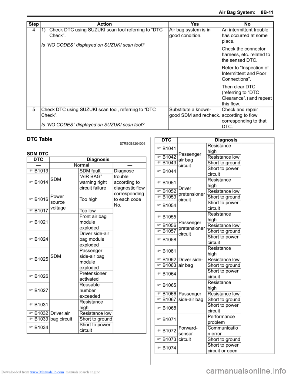
Downloaded from www.Manualslib.com manuals search engine Air Bag System: 8B-11
DTC TableS7RS0B8204003
SDM DTC4 1) Check DTC using SUZUKI scan tool referring to “DTC
Check”.
Is “NO CODES” displayed on SUZUKI scan tool? Air bag system is in
good condition.
An intermittent trouble
has occurred at some
place.
Check the connector
harness, etc. related to
the sensed DTC.
Refer to “Inspection of
Intermittent and Poor
Connections”.
Then clear DTC
(referring to “DTC
Clearance”.) and repeat
this flow.
5 Check DTC using SUZUKI scan tool, referring to “DTC Check”.
Is “NO CODES” displayed on SUZUKI scan tool? Substitute a known-
good SDM and recheck.
Check and repair
according to flow
corresponding to that
DTC.
Step Action Yes No
DTC
Diagnosis
—N orm al —
�) B1013
SDM SDM fault Diagnose
trouble
according to
diagnostic flow
corresponding
to each code
No.
�)
B1014 “AIR BAG”
warning right
circuit failure
�) B1016 Power
source
voltage Too high
�) B1017 Too low
�) B1021
SDM Front air bag
module
exploded
�) B1024 Driver side-air
bag module
exploded
�) B1025 Passenger
side-air bag
module
exploded
�) B1026 Pretensioner
activated
�) B1027 Reusable
number
exceeded
�) B1031
Driver air
bag circuit Resistance
high
�) B1032 Resistance low
�) B1033 Short to ground
�) B1034 Short to power
circuit
�)
B1041
Passenger
air bag
circuit Resistance
high
�) B1042 Resistance low
�) B1043 Short to ground
�) B1044 Short to power
circuit
�) B1051
Driver
pretensioner
circuit Resistance
high
�) B1052 Resistance low
�) B1053 Short to ground
�) B1054 Short to power
circuit
�) B1055
Passenger
pretensioner
circuit Resistance
high
�) B1056 Resistance low
�) B1057 Short to ground
�) B1058 Short to power
circuit
�) B1061
Driver side-
air bag Resistance
high
�) B1062 Resistance low
�) B1063 Short to ground
�) B1064 Short to power
circuit
�) B1065
Passenger
side-air bag Resistance
high
�) B1066 Resistance low
�) B1067 Short to ground
�) B1068 Short to power
circuit
�) B1071
Forward-
sensor
circuit Performance
problem
�) B1072 Communicatio
n error
�) B1073 Short to ground
�) B1074 Short to power
circuit or open
DTC Diagnosis
Page 1401 of 1496
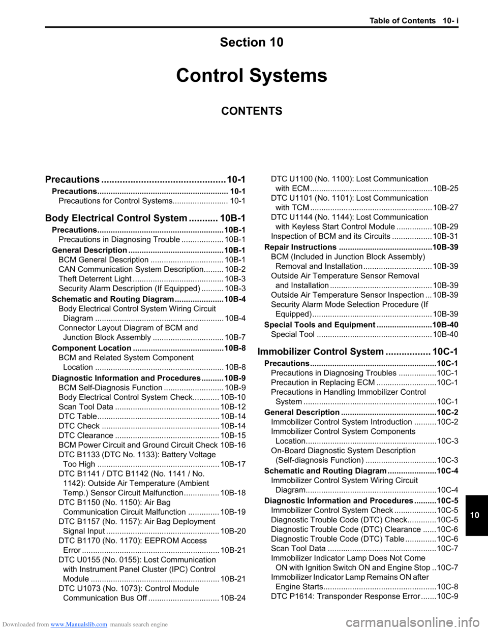
Downloaded from www.Manualslib.com manuals search engine Table of Contents 10- i
10
Section 10
CONTENTS
Control Systems
Precautions ............................................... 10-1
Precautions........................................................... 10-1
Precautions for Control Systems......................... 10-1
Body Electrical Contro l System ........... 10B-1
Precautions......................................................... 10B-1
Precautions in Diagnosing Trouble ................... 10B-1
General Description ........................................... 10B-1 BCM General Description ................................. 10B-1
CAN Communication System Description......... 10B-2
Theft Deterrent Light ......................................... 10B-3
Security Alarm Description (If Equipped) .......... 10B-3
Schematic and Routing Diagram ...................... 10B-4 Body Electrical Control System Wiring Circuit Diagram .......................................................... 10B-4
Connector Layout Diagram of BCM and Junction Block Assembly ................................ 10B-7
Component Locatio n ......................................... 10B-8
BCM and Related System Component Location .......................................................... 10B-8
Diagnostic Information an d Procedures .......... 10B-9
BCM Self-Diagnosis Function ........................... 10B-9
Body Electrical Control System Check............ 10B-10
Scan Tool Data ............................................... 10B-12
DTC Table ....................................................... 10B-14
DTC Check ..................................................... 10B-14
DTC Clearance ............................................... 10B-15
BCM Power Circuit and Ground Circuit Check 10B-16
DTC B1133 (DTC No. 1133): Battery Voltage Too High ....................................................... 10B-17
DTC B1141 / DTC B1142 (No. 1141 / No. 1142): Outside Air Temperature (Ambient
Temp.) Sensor Circuit Ma lfunction ................ 10B-18
DTC B1150 (No. 1150): Air Bag Communication Circuit Malfunction .............. 10B-19
DTC B1157 (No. 1157): Air Bag Deployment Signal Input ................................................... 10B-20
DTC B1170 (No. 1170 ): EEPROM Access
Error .............................................................. 10B-21
DTC U0155 (No. 0155): Lost Communication with Instrument Panel Cluster (IPC) Control
Module .......................................................... 10B-21
DTC U1073 (No. 1073): Control Module Communication Bus Off ................................ 10B-24 DTC U1100 (No. 1100): Lost Communication
with ECM ....................................................... 10B-25
DTC U1101 (No. 1101): Lost Communication with TCM ....................................................... 10B-27
DTC U1144 (No. 1144): Lost Communication with Keyless Start Control Module ................ 10B-29
Inspection of BCM and its Circuits .................. 10B-31
Repair Instructions ........... ...............................10B-39
BCM (Included in Junction Block Assembly) Removal and Installation ............................... 10B-39
Outside Air Temperature Sensor Removal and Installation .............................................. 10B-39
Outside Air Temperature Sensor Inspection ... 10B-39
Security Alarm Mode Selection Procedure (If Equipped) ...................................................... 10B-39
Special Tools and Equipmen t .........................10B-40
Special Tool .................................................... 10B-40
Immobilizer Control Syst em ................. 10C-1
Precautions.........................................................10C-1
Precautions in Diagnosing Troubles .................10C-1
Precaution in Replacing ECM ...........................10C-1
Precautions in Handli ng Immobilizer Control
System ............................................................10C-1
General Description ...........................................10C-2 Immobilizer Control System Introduction ..........10C-2
Immobilizer Control System Components Location...........................................................10C-3
On-Board Diagnostic System Description (Self-diagnosis Function) ................................10C-3
Schematic and Routing Diag ram ......................10C-4
Immobilizer Control System Wiring Circuit Diagram...........................................................10C-4
Diagnostic Information an d Procedures ..........10C-5
Immobilizer Control System Check ...................10C-5
Diagnostic Trouble Code (DTC) Check.............10C-5
Diagnostic Trouble Code (DTC) Clearance ......10C-6
Diagnostic Trouble Code (DTC) Table ..............10C-6
Scan Tool Data .................................................10C-7
Immobilizer Indicator Lamp Does Not Come ON with Ignition Switch ON and Engine Stop ..10C-7
Immobilizer Indicator Lamp Remains ON after Engine Starts...................................................10C-8
DTC P1614: Transponder Re sponse Error .......10C-9
Page 1402 of 1496
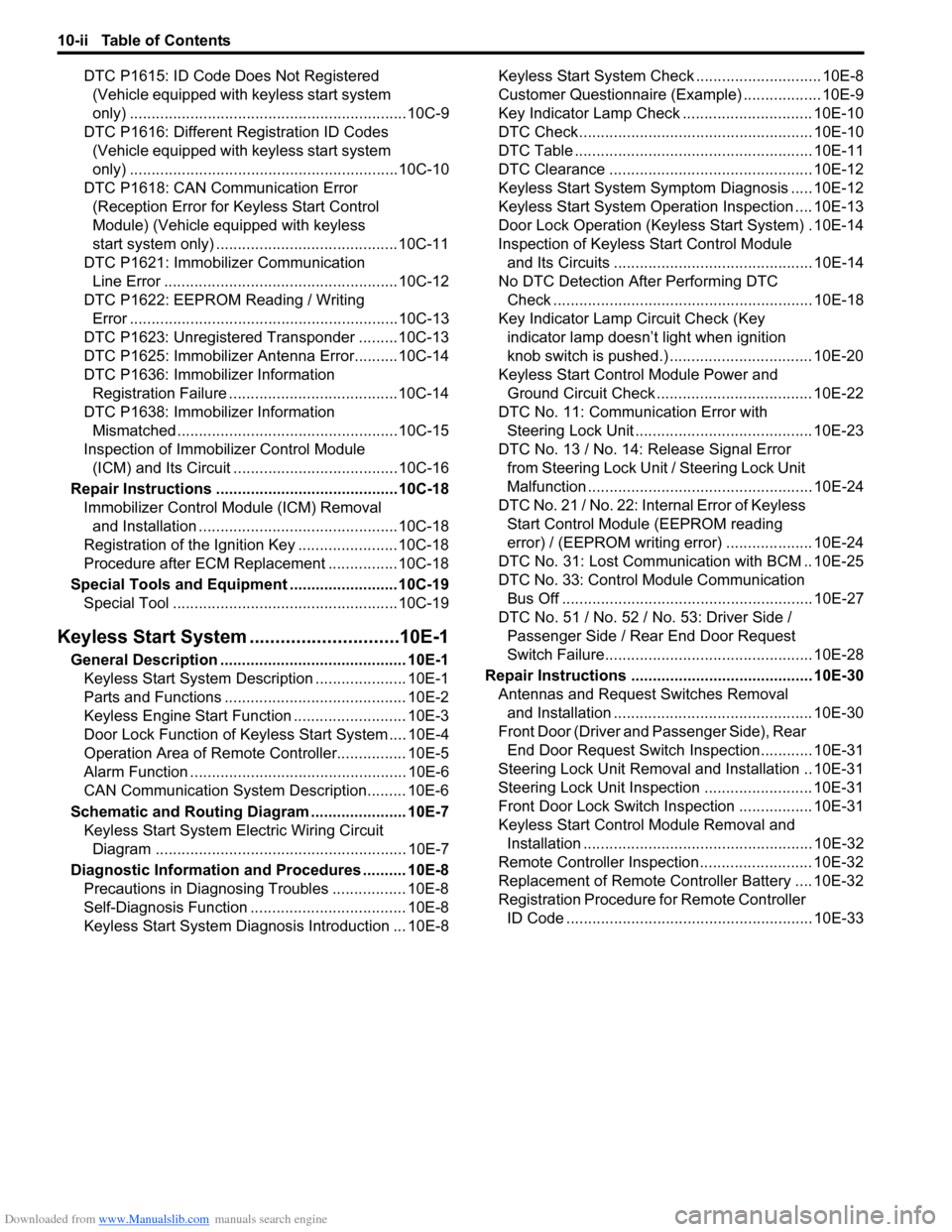
Downloaded from www.Manualslib.com manuals search engine 10-ii Table of Contents
DTC P1615: ID Code Does Not Registered (Vehicle equipped with keyless start system
only) ................................................................10C-9
DTC P1616: Different Registration ID Codes (Vehicle equipped with keyless start system
only) ..............................................................10C-10
DTC P1618: CAN Communication Error (Reception Error for Keyless Start Control
Module) (Vehicle equipped with keyless
start system only) ..........................................10C-11
DTC P1621: Immobilizer Communication Line Error ......................................................10C-12
DTC P1622: EEPROM Reading / Writing Error ..............................................................10C-13
DTC P1623: Unregistered Transponder .........10C-13
DTC P1625: Immobilizer An tenna Error..........10C-14
DTC P1636: Immobilizer Information Registration Failure .......................................10C-14
DTC P1638: Immobilizer Information Mismatched ...................................................10C-15
Inspection of Immobilizer Control Module (ICM) and Its Circuit ....... ...............................10C-16
Repair Instructions ........... ...............................10C-18
Immobilizer Control Mo dule (ICM) Removal
and Installation ..............................................10C-18
Registration of the Ignition Key .......................10C-18
Procedure after ECM Replacement ................10C-18
Special Tools and Equipmen t .........................10C-19
Special Tool ....................................................10C-19
Keyless Start System ....... ......................10E-1
General Description ........................................... 10E-1
Keyless Start System Description ..................... 10E-1
Parts and Functions .......................................... 10E-2
Keyless Engine Start Function .......................... 10E-3
Door Lock Function of Keyless Start System .... 10E-4
Operation Area of Remote Controller................ 10E-5
Alarm Function .................................................. 10E-6
CAN Communication System Description......... 10E-6
Schematic and Routing Diagram ...................... 10E-7 Keyless Start System El ectric Wiring Circuit
Diagram .......................................................... 10E-7
Diagnostic Information and Procedures .......... 10E-8 Precautions in Diagnosing Troubles ................. 10E-8
Self-Diagnosis Function .................................... 10E-8
Keyless Start System Diagn osis Introduction ... 10E-8 Keyless Start System Chec
k ............................. 10E-8
Customer Questionnaire (E xample) .................. 10E-9
Key Indicator Lamp Check .............................. 10E-10
DTC Check...................................................... 10E-10
DTC Table ....................................................... 10E-11
DTC Clearance ............................................... 10E-12
Keyless Start System Symp tom Diagnosis ..... 10E-12
Keyless Start System Operation Inspection .... 10E-13
Door Lock Operation (Keyless Start System) . 10E-14
Inspection of Keyless Start Control Module and Its Circuits .............................................. 10E-14
No DTC Detection After Performing DTC Check ............................................................ 10E-18
Key Indicator Lamp Circuit Check (Key indicator lamp doesn’t light when ignition
knob switch is pushed.) ................................. 10E-20
Keyless Start Control Module Power and Ground Circuit Check .................................... 10E-22
DTC No. 11: Communi cation Error with
Steering Lock Unit ......................................... 10E-23
DTC No. 13 / No. 14: Release Signal Error from Steering Lock Unit / Steering Lock Unit
Malfunction .................................................... 10E-24
DTC No. 21 / No. 22: Internal Error of Keyless Start Control Module (EEPROM reading
error) / (EEPROM writing error) ............ ........ 10E-24
DTC No. 31: Lost Commun ication with BCM .. 10E-25
DTC No. 33: Control Module Communication
Bus Off .......................................................... 10E-27
DTC No. 51 / No. 52 / No. 53: Driver Side / Passenger Side / Rear End Door Request
Switch Failure................................................ 10E-28
Repair Instructions ............ .............................. 10E-30
Antennas and Request Switches Removal and Installation .............................................. 10E-30
Front Door (Driver and Passenger Side), Rear End Door Request Switch Inspection............ 10E-31
Steering Lock Unit Removal and Installation .. 10E-31
Steering Lock Unit Inspection ......................... 10E-31
Front Door Lock Switch In spection ................. 10E-31
Keyless Start Control Module Removal and Installation ..................................................... 10E-32
Remote Controller Inspection.......................... 10E-32
Replacement of Remote Controller Battery .... 10E-32
Registration Procedure for Remote Controller
ID Code ......................................................... 10E-33