Ect sensors SUZUKI SWIFT 2007 2.G Service Owner's Guide
[x] Cancel search | Manufacturer: SUZUKI, Model Year: 2007, Model line: SWIFT, Model: SUZUKI SWIFT 2007 2.GPages: 1496, PDF Size: 34.44 MB
Page 998 of 1496
Downloaded from www.Manualslib.com manuals search engine 7B-50 Air Conditioning System: Automatic Type
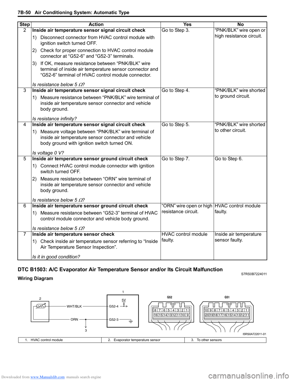
DTC B1503: A/C Evaporator Air Temperature Sensor and/or Its Circuit MalfunctionS7RS0B7224011
Wiring Diagram2
Inside air temperature sensor signal circuit check
1) Disconnect connector from HVAC control module with
ignition switch turned OFF.
2) Check for proper connection to HVAC control module connector at “G52-6” and “G52-3” terminals.
3) If OK, measure resistance between “PNK/BLK” wire terminal of inside air temp erature sensor connector and
“G52-6” terminal of HVAC control module connector.
Is resistance below 5
Ω? Go to Step 3. “PNK/BLK” wire open or
high resistance circuit.
3 Inside air temperature sensor signal circuit check
1) Measure resistance between “PNK/BLK” wire terminal of
inside air temperature sensor connector and vehicle
body ground.
Is resistance infinity? Go to Step 4.
“PNK/BLK” wire shorted
to ground circuit.
4 Inside air temperature sensor signal circuit check
1) Measure voltage between “PNK/BLK” wire terminal of
inside air temperature sensor connector and vehicle
body ground with ignition switch turned ON.
Is voltage 0 V? Go to Step 5.
“PNK/BLK” wire shorted
to other circuit.
5 Inside air temperature sensor ground circuit check
1) Connect HVAC control module connector with ignition
switch turned OFF.
2) Measure resistance between “ORN” wire terminal of inside air temperature sensor connector and vehicle
body ground.
Is resistance below 5
Ω? Go to Step 7. Go to Step 6.
6 Inside air temperature sensor ground circuit check
1) Measure resistance between “G52-3” terminal of HVAC
control module connector and vehicle body ground.
Is resistance below 5
Ω? “ORN” wire open or high
resistance circuit.
HVAC control module
faulty.
7 Inside air temperature sensor check
1) Check inside air temperature sensor referring to “Inside
Air Temperature Sensor Inspection”.
Is it in good condition? HVAC control module
faulty.
Inside air temperature
sensor faulty.
Step Action Yes No
5V
WHT/BLK
ORN G52-4
G52-3
2
1
3
7812910
65 431516 14 13 12 11
G52
789101920121112
65 431718 16 15 14 13
G51
I5RS0A722011-01
1. HVAC control module
2. Evaporator temperature sensor 3. To other sensors
Page 1001 of 1496
Downloaded from www.Manualslib.com manuals search engine Air Conditioning System: Automatic Type 7B-53
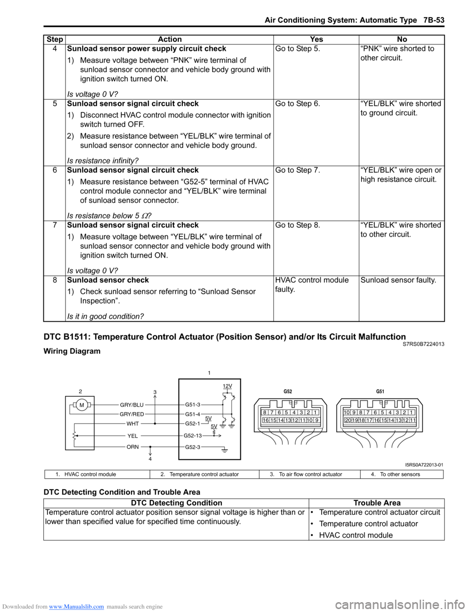
DTC B1511: Temperature Control Actuator (Position Sensor) and/or Its Circuit MalfunctionS7RS0B7224013
Wiring Diagram
DTC Detecting Condition and Trouble Area4
Sunload sensor power supply circuit check
1) Measure voltage between “PNK” wire terminal of
sunload sensor connector and vehicle body ground with
ignition switch turned ON.
Is voltage 0 V? Go to Step 5. “PNK” wire shorted to
other circuit.
5 Sunload sensor signal circuit check
1) Disconnect HVAC control modul e connector with ignition
switch turned OFF.
2) Measure resistance between “YEL/BLK” wire terminal of sunload sensor connector and vehicle body ground.
Is resistance infinity? Go to Step 6. “YEL/BLK” wire shorted
to ground circuit.
6 Sunload sensor signal circuit check
1) Measure resistance between “G52-5” terminal of HVAC
control module connector and “YEL/BLK” wire terminal
of sunload sensor connector.
Is resistance below 5
Ω? Go to Step 7. “YEL/BLK” wire open or
high resistance circuit.
7 Sunload sensor signal circuit check
1) Measure voltage between “YEL/BLK” wire terminal of
sunload sensor connector and vehicle body ground with
ignition switch turned ON.
Is voltage 0 V? Go to Step 8.
“YEL/BLK” wire shorted
to other circuit.
8 Sunload sensor check
1) Check sunload sensor referring to “Sunload Sensor
Inspection”.
Is it in good condition? HVAC control module
faulty.
Sunload sensor faulty.
Step
Action YesNo
7812910
65 431516 14 13 12 11
G52
789101920121112
65 431718 16 15 14 13
G51
M 12V
5V 5V
YEL
WHT
GRY/BLU
GRY/RED
2
1
ORN
G51-3
G51-4
G52-1
G52-13
G52-3
3
4
I5RS0A722013-01
1. HVAC control module 2. Temperature control actuator 3. To air flow control actuator4. To other sensors
DTC Detecting Condition Trouble Area
Temperature control actuator position sensor signal voltage is higher than or
lower than specified value for specified time continuously. • Temperature control actuator circuit
• Temperature control actuator
• HVAC control module
Page 1003 of 1496
Downloaded from www.Manualslib.com manuals search engine Air Conditioning System: Automatic Type 7B-55
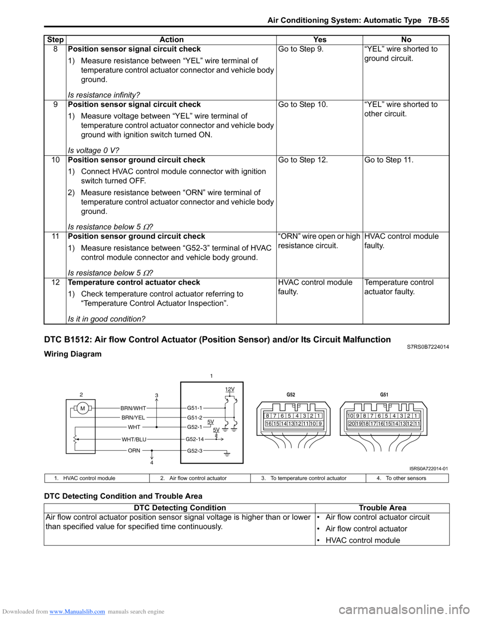
DTC B1512: Air flow Control Actuator (Position Sensor) and/or Its Circuit MalfunctionS7RS0B7224014
Wiring Diagram
DTC Detecting Condition and Trouble Area8
Position sensor signal circuit check
1) Measure resistance between “YEL” wire terminal of
temperature control actuator connector and vehicle body
ground.
Is resistance infinity? Go to Step 9. “YEL” wire shorted to
ground circuit.
9 Position sensor signal circuit check
1) Measure voltage between “YEL” wire terminal of
temperature control actuator connector and vehicle body
ground with ignition switch turned ON.
Is voltage 0 V? Go to Step 10. “YEL” wire shorted to
other circuit.
10 Position sensor ground circuit check
1) Connect HVAC control module connector with ignition
switch turned OFF.
2) Measure resistance between “ORN” wire terminal of temperature control actuator connector and vehicle body
ground.
Is resistance below 5
Ω? Go to Step 12. Go to Step 11.
11 Position sensor ground circuit check
1) Measure resistance between “G52-3” terminal of HVAC
control module connector and vehicle body ground.
Is resistance below 5
Ω? “ORN” wire open or high
resistance circuit.
HVAC control module
faulty.
12 Temperature control actuator check
1) Check temperature control actuator referring to
“Temperature Control Actuator Inspection”.
Is it in good condition? HVAC control module
faulty.
Temperature control
actuator faulty.
Step Action Yes No
7812910
65 431516 14 13 12 11
G52
789101920121112
65 431718 16 15 14 13
G51
M 12V
5V 5V
WHT/BLU
WHT
BRN/WHT
BRN/YEL
2
1
ORN
G51-1
G51-2
G52-1
G52-14
G52-3
3
4
I5RS0A722014-01
1. HVAC control module 2. Air flow control actuator3.To temperature control actuator 4. To other sensors
DTC Detecting Condition Trouble Area
Air flow control actuator position sensor signal voltage is higher than or lower
than specified value for specified time continuously. • Air flow control actuator circuit
• Air flow control actuator
• HVAC control module
Page 1005 of 1496
Downloaded from www.Manualslib.com manuals search engine Air Conditioning System: Automatic Type 7B-57
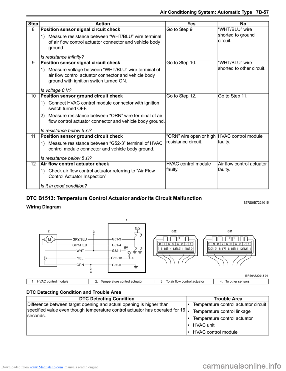
DTC B1513: Temperature Control Actuator and/or Its Circuit MalfunctionS7RS0B7224015
Wiring Diagram
DTC Detecting Condition and Trouble Area8
Position sensor signal circuit check
1) Measure resistance between “WHT/BLU” wire terminal
of air flow control actuator connector and vehicle body
ground.
Is resistance infinity? Go to Step 9. “WHT/BLU” wire
shorted to ground
circuit.
9 Position sensor signal circuit check
1) Measure voltage between “WHT/BLU” wire terminal of
air flow control actuator connector and vehicle body
ground with ignition switch turned ON.
Is voltage 0 V? Go to Step 10. “WHT/BLU” wire
shorted to other circuit.
10 Position sensor ground circuit check
1) Connect HVAC control module connector with ignition
switch turned OFF.
2) Measure resistance between “ORN” wire terminal of air flow control actuator connector and vehicle body ground.
Is resistance below 5
Ω? Go to Step 12. Go to Step 11.
11 Position sensor ground circuit check
1) Measure resistance between “G52-3” terminal of HVAC
control module connector and vehicle body ground.
Is resistance below 5
Ω? “ORN” wire open or high
resistance circuit.
HVAC control module
faulty.
12 Air flow control actuator check
1) Check air flow control actuator referring to “Air Flow
Control Actuator Inspection”.
Is it in good condition? HVAC control module
faulty.
Air flow control actuator
faulty.
Step Action Yes No
7812910
65 431516 14 13 12 11
G52
789101920121112
65 431718 16 15 14 13
G51
M 12V
5V 5V
YEL
WHT
GRY/BLU
GRY/RED
2
1
ORN
G51-3
G51-4
G52-1
G52-13
G52-3
3
4
I5RS0A722013-01
1. HVAC control module 2. Temperature control actuator 3. To air flow control actuator 4. To other sensors
DTC Detecting Condition Trouble Area
Difference between target opening an d actual opening is higher than
specified value even though temperature control actuator has operated for 16
seconds. • Temperature control actuator circuit
• Temperature control linkage
• Temperature control actuator
• HVAC unit
• HVAC control module
Page 1008 of 1496
Downloaded from www.Manualslib.com manuals search engine 7B-60 Air Conditioning System: Automatic Type
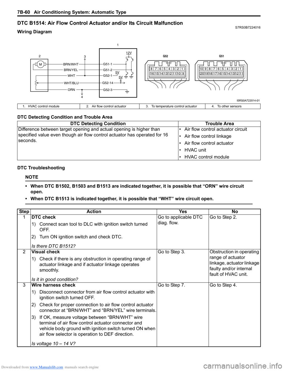
DTC B1514: Air Flow Control Actuator and/or Its Circuit MalfunctionS7RS0B7224016
Wiring Diagram
DTC Detecting Condition and Trouble Area
DTC Troubleshooting
NOTE
• When DTC B1502, B1503 and B1513 are indicated together, it is possible that “ORN” wire circuit open.
• When DTC B1513 is indicated together, it is possible that “WHT” wire circuit open.
7812910
65 431516 14 13 12 11
G52
789101920121112
65 431718 16 15 14 13
G51
M 12V
5V 5V
WHT/BLU
WHT
BRN/WHT
BRN/YEL
2
1
ORN
G51-1
G51-2
G52-1
G52-14
G52-3
3
4
I5RS0A722014-01
1. HVAC control module 2. Air flow control actuator3. To temperature control actuator 4. To other sensors
DTC Detecting Condition Trouble Area
Difference between target opening and actual opening is higher than
specified value even though air flow control actuator has operated for 16
seconds. • Air flow control actuator circuit
• Air flow control linkage
• Air flow control actuator
• HVAC unit
• HVAC control module
Step
Action YesNo
1 DTC check
1) Connect scan tool to DLC with ignition switch turned
OFF.
2) Turn ON ignition switch and check DTC.
Is there DTC B1512? Go to applicable DTC
diag. flow.
Go to Step 2.
2 Visual check
1) Check if there is any obstruction in operating range of
actuator linkage and if actuator linkage operates
smoothly.
Is it in good condition? Go to Step 3.
Obstruction in operating
range of actuator
linkage, actuator linkage
faulty and/or internal
fault of HVAC unit.
3 Wire harness check
1) Disconnect connector from air flow control actuator with
ignition switch turned OFF.
2) Check for proper connection to air flow control actuator
connector at “BRN/WHT” and “BRN/YEL” wire terminals.
3) If OK, measure voltage between “BRN/WHT” wire terminal of air flow control actuator connector and
vehicle body ground with ignition switch turned ON when
air flow selector is operation to DEF direction.
Is voltage 10 – 14 V? Go to Step 7.
Go to Step 4.
Page 1017 of 1496
Downloaded from www.Manualslib.com manuals search engine Air Conditioning System: Automatic Type 7B-69
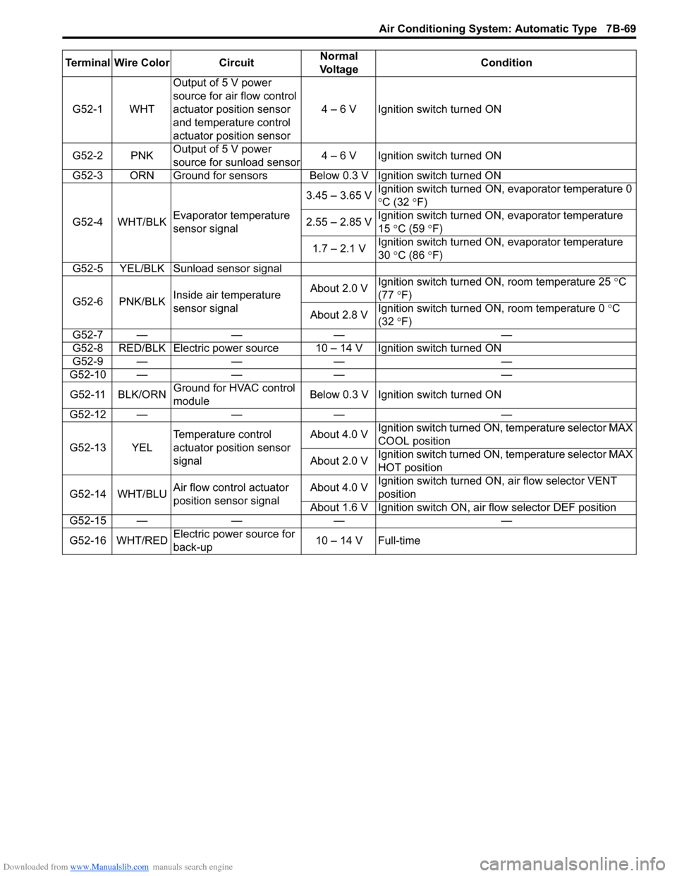
Terminal Wire Color CircuitNormal
Vo l ta g e Condition
G52-1 WHT Output of 5 V power
source for air flow control
actuator position sensor
and temperature control
actuator position sensor 4 – 6 V Ignition switch turned ON
G52-2 PNK Output of 5 V power
source for sunload sensor 4 – 6 V Ignition switch turned ON
G52-3 ORN Ground for sensors Below 0.3 V Ignition switch turned ON
G52-4 WHT/BLK Evaporator temperature
sensor signal 3.45 – 3.65 V
Ignition switch turned ON, evaporator temperature 0
°
C (32 °F)
2.55 – 2.85 V Ignition switch turned ON, evaporator temperature
15
°C (59 ° F)
1.7 – 2.1 V Ignition switch turned ON, evaporator temperature
30
°C (86 ° F)
G52-5 YEL/BLK Sunload sensor signal
G52-6 PNK/BLK Inside air temperature
sensor signal About 2.0 V
Ignition switch turned ON, room temperature 25
°C
(77 °F)
About 2.8 V Ignition switch turned ON, room temperature 0
°C
(32 °F)
G52-7 — — — —
G52-8 RED/BLK Electric power source 10 – 14 V Ignition switch turned ON
G52-9 — — — —
G52-10 — — — —
G52-11 BLK/ORN Ground for HVAC control
module Below 0.3 V Ignition
switch turned ON
G52-12 — — — —
G52-13 YEL Temperature control
actuator position sensor
signal About 4.0 V
Ignition switch turned ON, temperature selector MAX
COOL position
About 2.0 V Ignition switch turned ON, temperature selector MAX
HOT position
G52-14 WHT/BLU Air flow control actuator
position sensor signal About 4.0 V
Ignition switch turned ON
, air flow selector VENT
position
About 1.6 V Ignition switch ON, air flow selector DEF position
G52-15 — — — —
G52-16 WHT/RED Electric power source for
back-up 10 – 14 V Full-time
Page 1019 of 1496
Downloaded from www.Manualslib.com manuals search engine Air Conditioning System: Automatic Type 7B-71
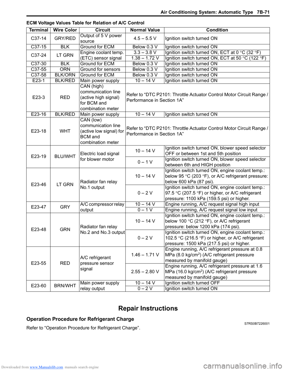
ECM Voltage Values Table for Relation of A/C Control
Repair Instructions
Operation Procedure for Refrigerant ChargeS7RS0B7226001
Refer to “Operation Procedure for Refrigerant Charge”.Terminal Wire Color Circuit Normal Value Condition
C37-14 GRY/RED Output of 5 V power
source 4.5 – 5.5 V Ignition switch turned ON
C37-15 BLK Ground for ECM Below 0.3 V Ignition switch turned ON
C37-24 LT GRN Engine coolant temp.
(ETC) sensor signal 3.3 – 3.8 V Ignition switch turned ON, ECT at 0
°C (32 ° F)
1.38 – 1.72 V Ignition switch turned ON, ECT at 50 °C (122 °F)
C37-30 BLK Ground for ECM Below 0.3 V Ignition switch turned ON
C37-55 ORN Ground for sensors Below 0.3 V Ignition switch turned ON
C37-58 BLK/ORN Ground for ECM Below 0.3 V Ignition switch turned ON E23-1 BLK/RED Main power supply 10 – 14 V Ignition switch turned ON
E23-3 RED CAN (high)
communication line
(active high signal)
for BCM and
combination meterRefer to “DTC P2101: Throttle Actu
ator Control Motor Circuit Range /
Performance in Section 1A”
E23-16 BLK/RED Main power supply 10 – 14 V Ignition switch turned ON
E23-18 WHT CAN (low)
communication line
(active low signal) for
BCM and
combination meterRefer to “DTC P2101: Throttle Actu
ator Control Motor Circuit Range /
Performance in Section 1A”
E23-19 BLU/WHT Electric load signal
for blower motor 10 – 14 V
Ignition switch turned ON, blower speed selector
OFF or between 1st and 5th position
0 – 1 V Ignition switch turned ON, blower speed selector
between 6th and HIGH position
E23-46 LT GRN Radiator fan relay
No.1 output 10 – 14 V
Ignition switch turned ON, engine coolant temp.:
below 95
°C (203 ° F), or A/C refrigerant pressure:
below 600 kPa (87 psi).
0 – 2 V Ignition switch turned ON, engine coolant temp.:
97.5
°C (207.5 °F) or higher, or A/C refrigerant
pressure: 1100 kPa (159.5 psi) or higher.
E23-47 GRY A/C compressor relay
output 10 – 14 V Engine running, A/C request signal high input
0 – 1 V Engine running, A/C request signal low input
E23-48 GRN Radiator fan relay
No.2 and No.3 output 10 – 14 V
Ignition switch turned ON, engine coolant temp.:
below 100
°C (212 °F), or A/C refrigerant
pressure: below 1200 kPa (174 psi).
0 – 2 V Ignition switch turned ON, engine coolant temp.:
102.5
°C (216.5 ° F) or higher, or A/C refrigerant
pressure: 1500 kPa (217.5 psi) or higher.
E23-55 RED A/C refrigerant
pressure sensor
signal 1.46 – 1.71 V
Engine running, A/C refrigerant pressure at 0.8
MPa (8.0 kg/cm
2) (A/C refrigerant pressure
measured by manifold gauge)
2.55 – 2.80 V Engine running, A/C refrigerant pressure at 1.6
MPa (16.0 kg/cm
2) (A/C refrigerant pressure
measured by manifold gauge)
E23-60 BRN/WHT Main power supply
relay output 10 – 14 V Ignition switch turned OFF
0 – 2 V Ignition switch turned ON
Page 1134 of 1496
Downloaded from www.Manualslib.com manuals search engine 8B-96 Air Bag System:
Repair and Inspection Required after AccidentS7RS0B8204049
CAUTION!
• All air bag system components, including the electrical harness (component
mounting points), must be inspected after
an accident. If any components are
damaged or bent, they must be replaced
even if air bag system activation did not
occur.
• Never use air bag system parts from another vehicle.
• Do not attempt to service the parts below. Service of these parts is by replacement
only.
– Driver / Passenger air bag (inflator) modules
– Driver / Passenger side-air bag (inflator) modules
– Driver / Passenger side curtain-air bag (inflator) modules
– Driver / Passenger seat belt pretensioners
–Forward-sensor
– Driver / Passenger side-sensors
–SDM
– Contact coil and combination switch assembly
– Air bag wire harness in main harness, instrument panel harness and floor
harness.
• Proper operation of the sensors and air bag system requires that any repairs to the
vehicle structure return it to its original
production configuration.
CAUTION!
After detecting one time of such collision as
to meet deployment conditions, the SDM
must not be used.
Refer to “Air Bag Diagnostic System Check”
when checking the SDM.
Accident with Deployment / Activation – Component
Replacement
When driver and passenger air bags are deployed, the
following components must be replaced.
• Driver and passenger air bag (inflator) modules
• Driver and passenger seat belt pretensioners
• SDM after detecting such collision as to meet
deployment conditions
• Forward-sensor
• Instrument panel When side-air bag and side curtain-air bag are deployed,
the following components must be replaced.
• Deployed side-air bag (inflator) module
• Deployed side curtain-air bag (inflator) module
• Side-sensor
•SDM
Accident with or without Deployment / Activation –
Component Inspections
Certain air bag and restraint system components must
be inspected after any crash, whether the air bag system
activated or not. If any faul
ty condition is found in the
following checks, replace faulty part.
Those components are:
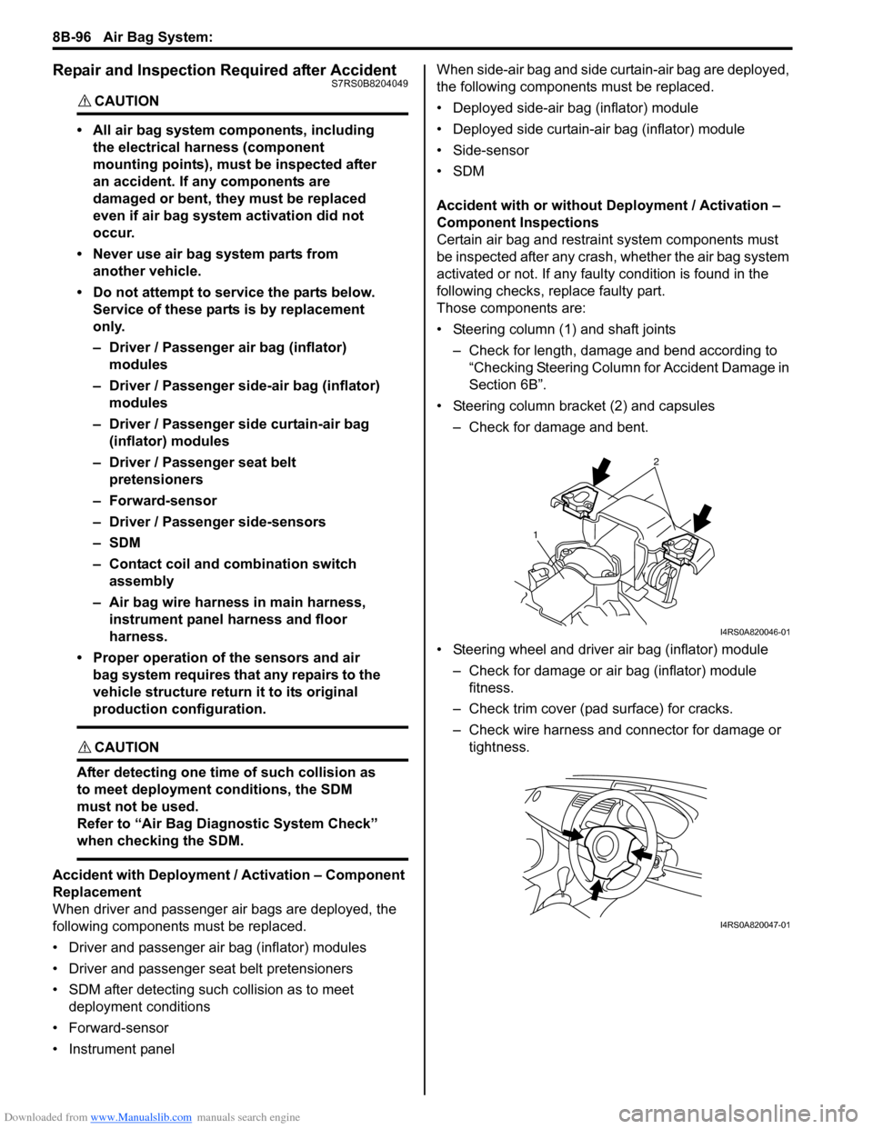
• Steering column (1) and shaft joints
– Check for length, damage and bend according to “Checking Steering Column for Accident Damage in
Section 6B”.
• Steering column bracket (2) and capsules – Check for damage and bent.
• Steering wheel and driver air bag (inflator) module – Check for damage or air bag (inflator) module fitness.
– Check trim cover (pad surface) for cracks.
– Check wire harness and connector for damage or tightness.
2
1
I4RS0A820046-01
I4RS0A820047-01