thread SUZUKI SWIFT 2007 2.G Service Owner's Guide
[x] Cancel search | Manufacturer: SUZUKI, Model Year: 2007, Model line: SWIFT, Model: SUZUKI SWIFT 2007 2.GPages: 1496, PDF Size: 34.44 MB
Page 922 of 1496
Downloaded from www.Manualslib.com manuals search engine 6C-40 Power Assisted Steering System:
Repair Instructions
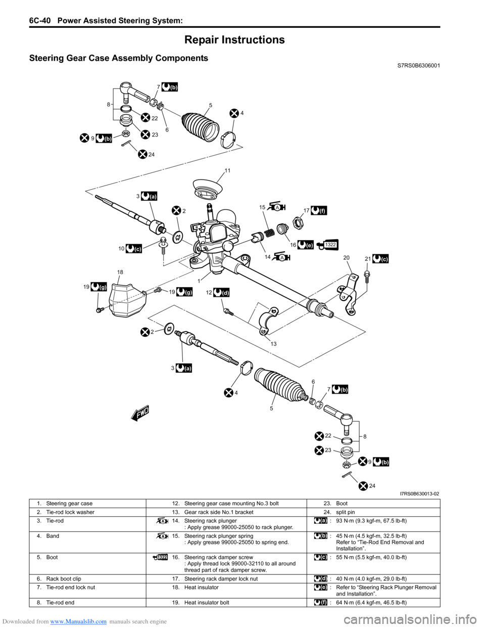
Steering Gear Case Assembly ComponentsS7RS0B6306001
3(a)
10
(c) 2
3
(a)
2 1
19
(g)
19 18(g) 6
11
8
9
(b) 7
(b)
22 23
24 4
5
14
15
16
(e)
17
(f)
12
(d) 21
(c)
20
4 6
5 7
(b)
9
(b)
8
13
22
23
24
A
A
1322
I7RS0B630013-02
1. Steering gear case 12. Steering gear case mounting No.3 bolt 23. Boot
2. Tie-rod lock washer 13. Gear rack side No.1 bracket 24. split pin
3. Tie-rod 14. Steering rack plunger
: Apply grease 99000-25050 to rack plunger. : 93 N
⋅m (9.3 kgf-m, 67.5 lb-ft)
4. Band 15. Steering rack plunger spring
: Apply grease 99000-25050 to spring end. : 45 N
⋅m (4.5 kgf-m, 32.5 lb-ft)
Refer to “Tie-Rod End Removal and
Installation”.
5. Boot 16. Steering rack damper screw
: Apply thread lock 99000-32110 to all around
thread part of rack damper screw. : 55 N
⋅m (5.5 kgf-m, 40.0 lb-ft)
6. Rack boot clip 17. Steering rack damper lock nut : 40 N⋅m (4.0 kgf-m, 29.0 lb-ft)
7. Tie-rod end lock nut 18. Heat insulator : Refer to “Steering Rack Plunger Removal
and Installation”.
8. Tie-rod end 19. Heat insulator bolt : 64 N⋅m (6.4 kgf-m, 46.5 lb-ft)
Page 923 of 1496
Downloaded from www.Manualslib.com manuals search engine Power Assisted Steering System: 6C-41
Tie-Rod End Boot On-Vehicle InspectionS7RS0B6306002
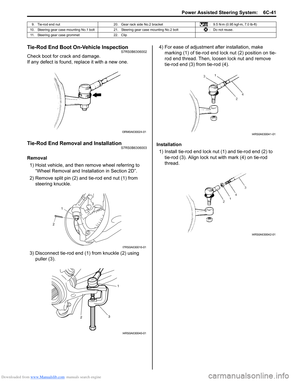
Check boot for crack and damage.
If any defect is found, replace it with a new one.
Tie-Rod End Removal and InstallationS7RS0B6306003
Removal1) Hoist vehicle, and then remove wheel referring to “Wheel Removal and Installation in Section 2D”.
2) Remove split pin (2) and tie-rod end nut (1) from steering knuckle.
3) Disconnect tie-rod end (1) from knuckle (2) using puller (3). 4) For ease of adjustment after installation, make
marking (1) of tie-rod end lock nut (2) position on tie-
rod end thread. Then, loosen lock nut and remove
tie-rod end (3) from tie-rod (4).
Installation 1) Install tie-rod end lock nut (1) and tie-rod end (2) to tie-rod (3). Align lock nut with mark (4) on tie-rod
thread.
9. Tie-rod end nut 20. Gear rack side No.2 bracket : 9.5 N⋅m (0.95 kgf-m, 7.0 lb-ft)
10. Steering gear case mounting No.1 bolt 21. Steering gear case mounting No.2 bolt : Do not reuse.
11. Steering gear case grommet 22. Clip
I3RM0A630024-01
21
I7RS0A630016-01
2 1
3
I4RS0A630040-01
I4RS0A630041-01
I4RS0A630042-01
Page 925 of 1496
Downloaded from www.Manualslib.com manuals search engine Power Assisted Steering System: 6C-43
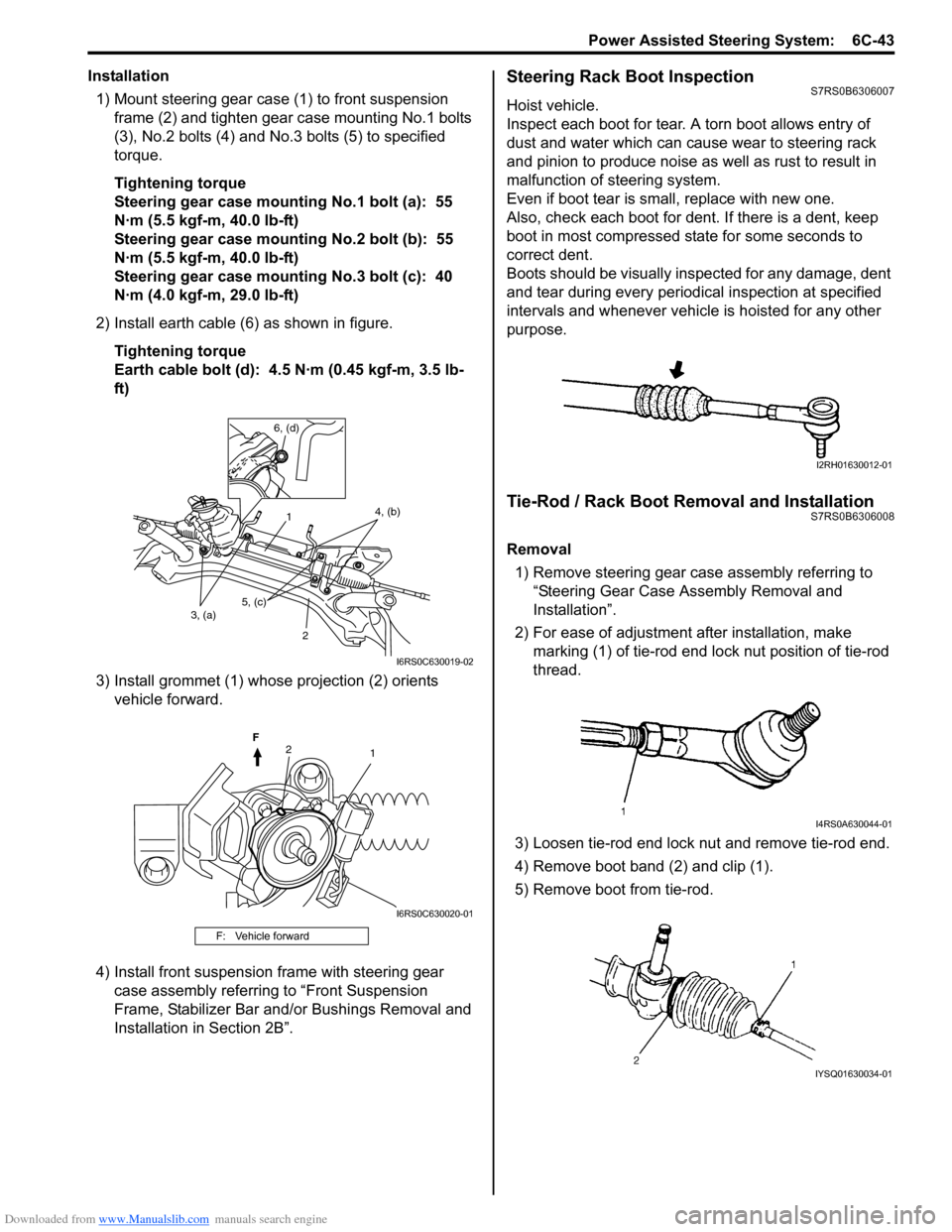
Installation1) Mount steering gear case (1) to front suspension frame (2) and tighten gear case mounting No.1 bolts
(3), No.2 bolts (4) and No .3 bolts (5) to specified
torque.
Tightening torque
Steering gear case mounting No.1 bolt (a): 55
N·m (5.5 kgf-m, 40.0 lb-ft)
Steering gear case mounting No.2 bolt (b): 55
N·m (5.5 kgf-m, 40.0 lb-ft)
Steering gear case mounting No.3 bolt (c): 40
N·m (4.0 kgf-m, 29.0 lb-ft)
2) Install earth cable (6) as shown in figure. Tightening torque
Earth cable bolt (d): 4.5 N·m (0.45 kgf-m, 3.5 lb-
ft)
3) Install grommet (1) whose projection (2) orients vehicle forward.
4) Install front suspension frame with steering gear case assembly referring to “Front Suspension
Frame, Stabilizer Bar and/or Bushings Removal and
Installation in Section 2B”.Steering Rack Boot InspectionS7RS0B6306007
Hoist vehicle.
Inspect each boot for tear. A torn boot allows entry of
dust and water which can cause wear to steering rack
and pinion to produce noise as well as rust to result in
malfunction of steering system.
Even if boot tear is small, replace with new one.
Also, check each boot for dent. If there is a dent, keep
boot in most compressed st ate for some seconds to
correct dent.
Boots should be visually inspected for any damage, dent
and tear during every periodical inspection at specified
intervals and whenever vehicle is hoisted for any other
purpose.
Tie-Rod / Rack Boot Removal and InstallationS7RS0B6306008
Removal
1) Remove steering gear case assembly referring to
“Steering Gear Case Assembly Removal and
Installation”.
2) For ease of adjustment after installation, make marking (1) of tie-rod end lock nut position of tie-rod
thread.
3) Loosen tie-rod end lock nut and remove tie-rod end.
4) Remove boot band (2) and clip (1).
5) Remove boot from tie-rod.
F: Vehicle forward
1 2
3, (a) 4, (b)
6, (d)
5, (c)
I6RS0C630019-02
12
F
I6RS0C630020-01
I2RH01630012-01
I4RS0A630044-01
IYSQ01630034-01
Page 927 of 1496
Downloaded from www.Manualslib.com manuals search engine Power Assisted Steering System: 6C-45
8) Install steering gear case assembly referring to “Steering Gear Case Assembly Removal and
Installation”.
Steering Rack Plunger Removal and InstallationS7RS0B6306009
Removal
1) Remove gear case assembly referring to “Steering
Gear Case Assembly Removal and Installation”.
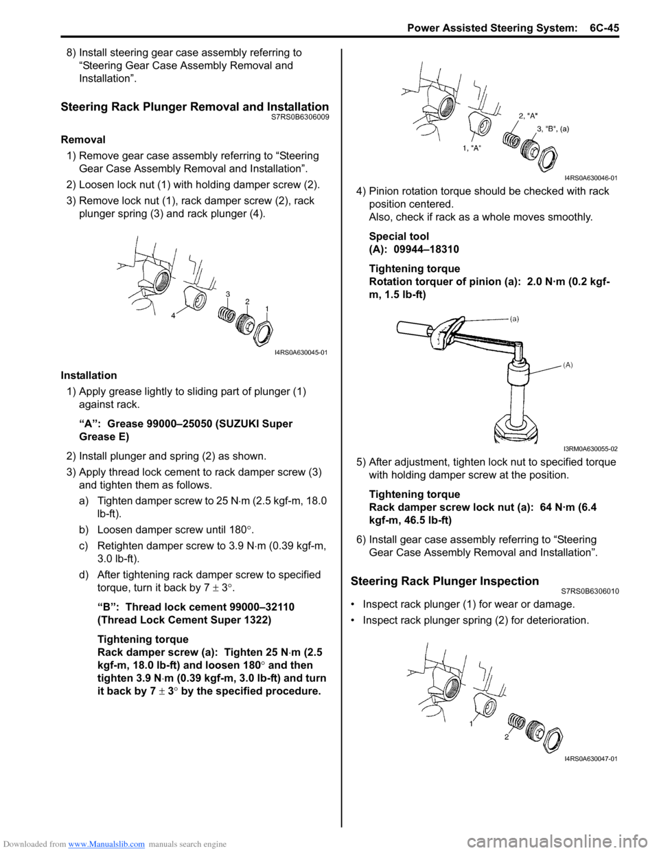
2) Loosen lock nut (1) with holding damper screw (2).
3) Remove lock nut (1), rack damper screw (2), rack plunger spring (3) and rack plunger (4).
Installation 1) Apply grease lightly to sliding part of plunger (1) against rack.
“A”: Grease 99000–25050 (SUZUKI Super
Grease E)
2) Install plunger and spring (2) as shown.
3) Apply thread lock cement to rack damper screw (3)
and tighten them as follows.
a) Tighten damper screw to 25 N ⋅m (2.5 kgf-m, 18.0
lb-ft).
b) Loosen damper screw until 180 °.
c) Retighten damper screw to 3.9 N ⋅m (0.39 kgf-m,
3.0 lb-ft).
d) After tightening rack damper screw to specified torque, turn it back by 7 ± 3°.
“B”: Thread lock cement 99000–32110
(Thread Lock Cement Super 1322)
Tightening torque
Rack damper screw (a): Tighten 25 N ⋅m (2.5
kgf-m, 18.0 lb-ft) and loosen 180° and then
tighten 3.9 N ⋅m (0.39 kgf-m, 3.0 lb-ft) and turn
it back by 7 ± 3° by the specified procedure. 4) Pinion rotation torque should be checked with rack
position centered.
Also, check if rack as a whole moves smoothly.
Special tool
(A): 09944–18310
Tightening torque
Rotation torquer of pinion (a): 2.0 N·m (0.2 kgf-
m, 1.5 lb-ft)
5) After adjustment, tighten lo ck nut to specified torque
with holding damper screw at the position.
Tightening torque
Rack damper screw lock nut (a): 64 N·m (6.4
kgf-m, 46.5 lb-ft)
6) Install gear case assembly referring to “Steering Gear Case Assembly Re moval and Installation”.
Steering Rack Plunger InspectionS7RS0B6306010
• Inspect rack plunger (1) for wear or damage.
• Inspect rack plunger spring (2) for deterioration.
I4RS0A630045-01
I4RS0A630046-01
I3RM0A630055-02
I4RS0A630047-01
Page 931 of 1496
Downloaded from www.Manualslib.com manuals search engine Power Assisted Steering System: 6C-49
Special Tools and Equipment
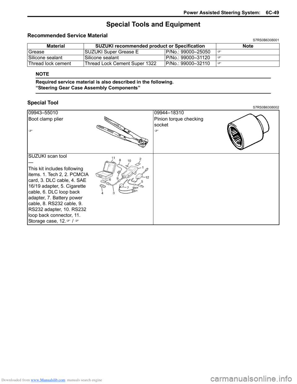
Recommended Service MaterialS7RS0B6308001
NOTE
Required service material is also described in the following.
“Steering Gear Case Assembly Components”
Special ToolS7RS0B6308002
Material SUZUKI recommended product or Specification Note
Grease SUZUKI Super Grease E P/No.: 99000–25050�)
Silicone sealant Silicone sealant P/No.: 99000–31120�)
Thread lock cement Thread Lock Cement Super 1322 P/No.: 99000–32110 �)
09943–5501009944–18310
Boot clamp plier Pinion torque checking
socket
�)�)
SUZUKI scan tool
—
This kit includes following
items. 1. Tech 2, 2. PCMCIA
card, 3. DLC cable, 4. SAE
16/19 adapter, 5. Cigarette
cable, 6. DLC loop back
adapter, 7. Battery power
cable, 8. RS232 cable, 9.
RS232 adapter, 10. RS232
loop back connector, 11.
Storage case, 12. �) / �)
Page 1032 of 1496
Downloaded from www.Manualslib.com manuals search engine 8A-1 Seat Belts:
Restraint
Seat Belts
Precautions
Precautions on Service and Diagnosis of Seat
Belt
S7RS0B8100001
WARNING!
If replacing seat belt is necessary, replace
buckle and seat belt assembly together as a
set. This is for the reason of ensuring locking
of tongue plate with buckle. If these parts are
replaced individually, such a locking
condition may become unreliable. For this
reason, SUZUKI will supply only the spare
buckle and seat belt assembly in a set part.
Before servicing or replacing seat belts, refer to the
following precautionary items.
• Seat belts should be normal relative to strap retractor and buckle portions. • Keep sharp edges and damaging objects away from
belts.
• Avoid bending or damaging any portion of belt buckle or latch plate.
• Do not bleach or dye belt webbing. (Use only mild soap and lukewarm water to clean it.)
• When installing a seat belt anchor bolt, it should be tightened by hand at first to prevent cross-threading
and then to specified torque.
• Do not attempt any repair s on retractor mechanisms
or retractor covers. Replace defective assemblies with
new replacement parts.
• Keep belts dry and clean at all times.
• If there exist any parts in question, replace such parts.
• Replace belts whose webbing is cut or otherwise damaged.
• Do not put anything into trim panel opening which seat belt webbing passes through.
General Description
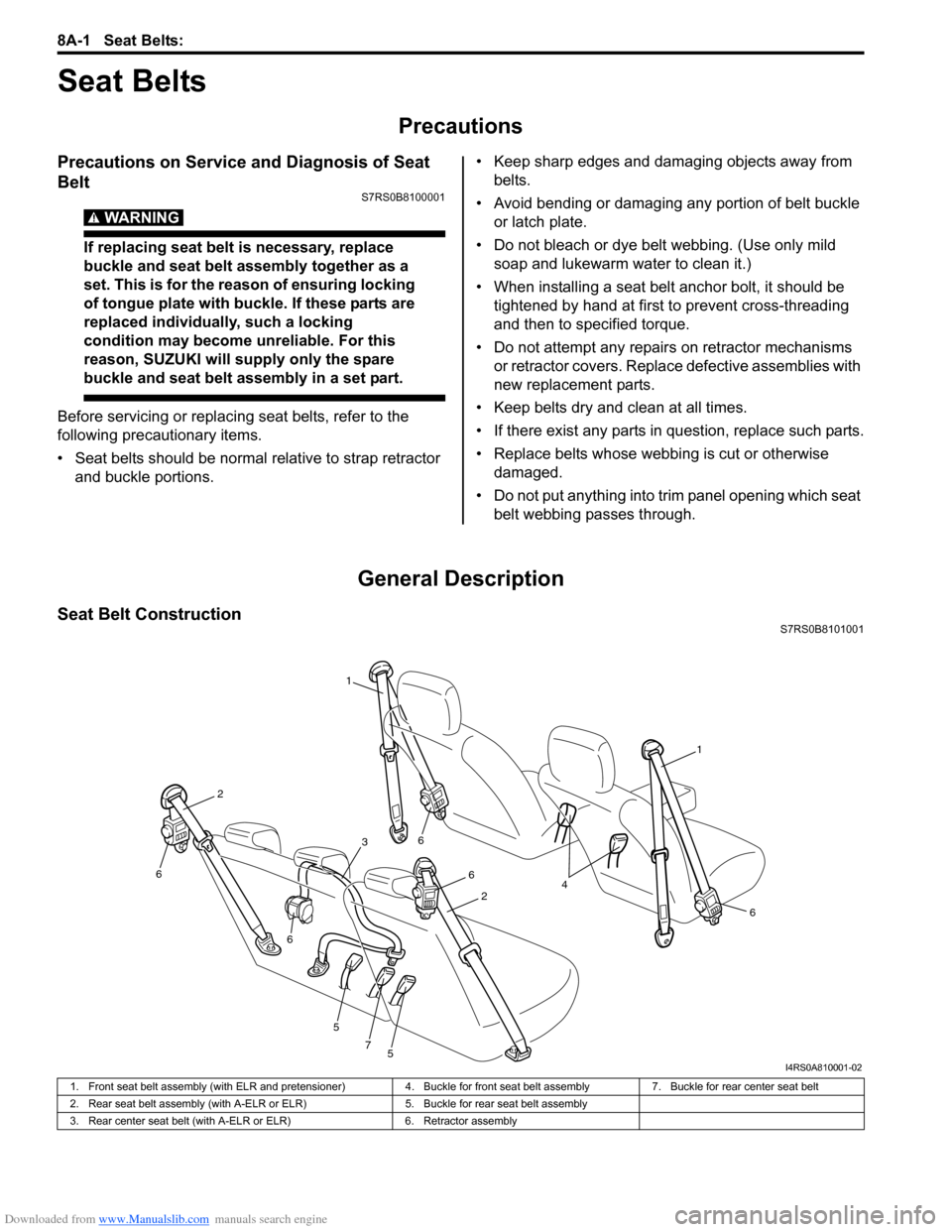
Seat Belt ConstructionS7RS0B8101001
1
1
6
6
6
5
5
7
6
6
2
2
3
4
I4RS0A810001-02
1. Front seat belt assembly (with ELR and pretensioner) 4. Buckle for front seat belt assembly7. Buckle for rear center seat belt
2. Rear seat belt assembly (with A-ELR or ELR) 5. Buckle for rear seat belt assembly
3. Rear center seat belt (with A-ELR or ELR) 6. Retractor assembly
Page 1035 of 1496
Downloaded from www.Manualslib.com manuals search engine Seat Belts: 8A-4
Front Seat Belt Removal and InstallationS7RS0B8106002
WARNING!
• Never attempt to disassemble or repair the seat belt pretensioner (retractor
assembly). If any abnormality is found, be
sure to replace it with new one as an
assembly.
• Be sure to read “Precautions on Service and Diagnosis of Seat Belt” before starting
to work and observe every precaution
during work. Ne glecting them may result in
personal injury or una ctivation of the seat
belt pretensioner when necessary.
Removal
1) Disconnect negative (–) cable at battery.
2) Disable air bag system. Refer to “Disabling Air Bag System in Section 8B”.
3) Remove center pillar lower trim.
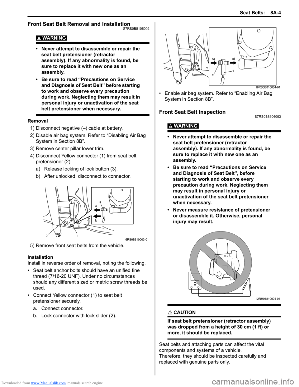
4) Disconnect Yellow connector (1) from seat belt pretensioner (2).
a) Release locking of lock button (3).
b) After unlocked, disconnect to connector.
5) Remove front seat belts from the vehicle.
Installation
Install in reverse order of removal, noting the following.
• Seat belt anchor bolts should have an unified fine thread (7/16-20 UNF). Under no circumstances
should any different sized or metric screw threads be
used.
• Connect Yellow connector (1) to seat belt pretensioner securely.
a. Connect connector.
b. Lock connector with lock slider (2). • Enable air bag system. Refer to “Enabling Air Bag
System in Section 8B”.
Front Seat Belt InspectionS7RS0B8106003
WARNING!
• Never attempt to disassemble or repair the seat belt pretensioner (retractor
assembly). If any abnormality is found, be
sure to replace it with new one as an
assembly.
• Be sure to read “Precautions on Service and Diagnosis of Seat Belt”, before
starting to work and observe every
precaution during work. Neglecting them
may result in personal injury or
unactivation of the seat belt pretensioner
when necessary.
• Never measure resistance of pretensioner or disassemble it. Otherwise, personal
injury may result.
CAUTION!
If seat belt pretensioner (retractor assembly)
was dropped from a height of 30 cm (1 ft) or
more, it should be replaced.
Seat belts and attaching parts can affect the vital
components and systems of a vehicle.
Therefore, they should be inspected carefully and
replaced with genuine parts only.
a
b
21 3I6RS0B810003-01
1
1
2
b)
a)
I6RS0B810004-01
I2RH01810004-01
Page 1038 of 1496
Downloaded from www.Manualslib.com manuals search engine 8A-7 Seat Belts:
Rear Seat Belt Removal and InstallationS7RS0B8106005
WARNING!
Be sure to read “Precautions on Service and
Diagnosis of Seat Belt” before starting to
work and observe every precaution during
work.
Removal1) Fold rear seats referring to “Folding Rear Seats” in Owners Manual.
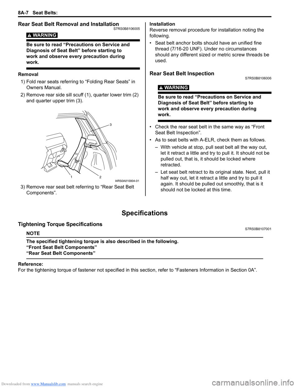
2) Remove rear side sill scuff (1), quarter lower trim (2)
and quarter upper trim (3).
3) Remove rear seat belt referring to “Rear Seat Belt Components”. Installation
Reverse removal procedure for installation noting the
following.
• Seat belt anchor bolts should have an unified fine
thread (7/16-20 UNF). Under no circumstances
should any different sized or metric screw threads be
used.Rear Seat Belt InspectionS7RS0B8106006
WARNING!
Be sure to read “Precautions on Service and
Diagnosis of Seat Belt” before starting to
work and observe every precaution during
work.
• Check the rear seat belt in the same way as “Front Seat Belt Inspection”.
• As to seat belts with A-ELR, check them as follows. – With vehicle at stop, pull seat belt all the way out, let it retract a little and try to pull it. It should not be
pulled out, that is, it should be locked where
retracted.
– Let seat belt retract to its original state. Next, pull it
half way out, let it retrac t a little and try to pull it
again. It should be pulled out smoothly, that is it
should not be locked at this time.
Specifications
Tightening Torque SpecificationsS7RS0B8107001
NOTE
The specified tightening torque is also described in the following.
“Front Seat Belt Components”
“Rear Seat Belt Components”
Reference:
For the tightening torque of fastener not specified in this section, refer to “Fasteners Information in Section 0A”.
3
2
1
I4RS0A810004-01
Page 1148 of 1496
Downloaded from www.Manualslib.com manuals search engine 8B-110 Air Bag System:
Installation
CAUTION!
Proper operation of forward-sensor requires
sensor be rigidly attached to vehicle
structure and that the arrow on sensor be
pointing toward the front of the vehicle.
1) Check that none of the following faulty conditions exists.
• Bend, deformity or rust of front panel.
• Foreign matter on mating surface of sensor.
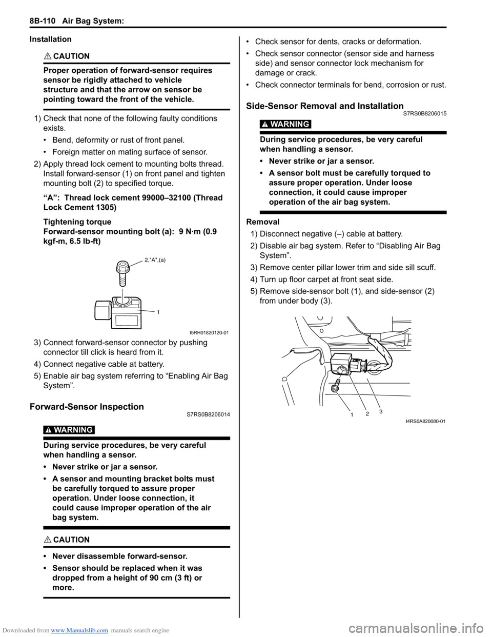
2) Apply thread lock cement to mounting bolts thread. Install forward-sensor (1) on front panel and tighten
mounting bolt (2) to specified torque.
“A”: Thread lock cement 99000–32100 (Thread
Lock Cement 1305)
Tightening torque
Forward-sensor mounting bolt (a): 9 N·m (0.9
kgf-m, 6.5 lb-ft)
3) Connect forward-sensor connector by pushing connector till click is heard from it.
4) Connect negative cable at battery.
5) Enable air bag system referring to “Enabling Air Bag System”.
Forward-Sensor InspectionS7RS0B8206014
WARNING!
During service procedures, be very careful
when handling a sensor.
• Never strike or jar a sensor.
• A sensor and mounting bracket bolts must be carefully torqued to assure proper
operation. Under loose connection, it
could cause improper operation of the air
bag system.
CAUTION!
• Never disassemble forward-sensor.
• Sensor should be replaced when it was dropped from a height of 90 cm (3 ft) or
more.
• Check sensor for dents, cracks or deformation.
• Check sensor connector (sensor side and harness side) and sensor connector lock mechanism for
damage or crack.
• Check connector terminals for bend, corrosion or rust.
Side-Sensor Removal and InstallationS7RS0B8206015
WARNING!
During service procedures, be very careful
when handling a sensor.
• Never strike or jar a sensor.
• A sensor bolt must be carefully torqued to assure proper operation. Under loose
connection, it could cause improper
operation of the air bag system.
Removal
1) Disconnect negative (–) cable at battery.
2) Disable air bag system. Re fer to “Disabling Air Bag
System”.
3) Remove center pillar lowe r trim and side sill scuff.
4) Turn up floor carpet at front seat side.
5) Remove side-sensor bolt (1), and side-sensor (2) from under body (3).
2,"A",(a)
1
I5RH01820120-01
1 23I4RS0A820080-01
Page 1165 of 1496
Downloaded from www.Manualslib.com manuals search engine Air Bag System: 8B-127
Recommended Service MaterialS7RS0B8208002
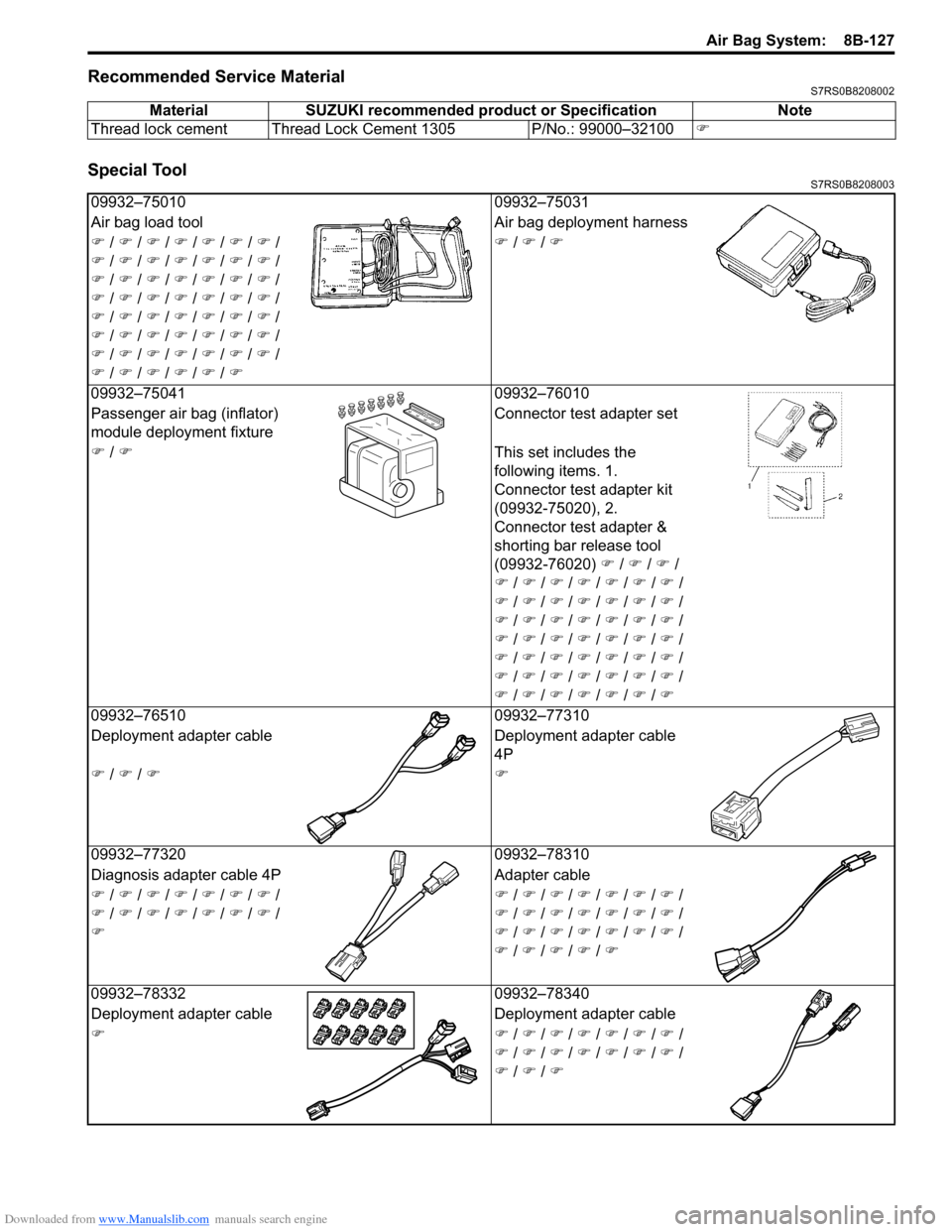
Special ToolS7RS0B8208003
MaterialSUZUKI recommended product or Specification Note
Thread lock cement Thread Lock Cement 1305 P/No.: 99000–32100 �)
09932–7501009932–75031
Air bag load tool Air bag deployment harness
�) / �) / �) / �) / �) / �) / �) /
�) / �) / �) / �) / �) / �) / �) /
�) / �) / �) / �) / �) / �) / �) /
�) / �) / �) / �) / �) / �) / �) /
�) / �) / �) / �) / �) / �) / �) /
�) / �) / �) / �) / �) / �) / �) /
�) / �) / �) / �) / �) / �) / �) /
�) / �) / �) / �) / �) / �) �)
/ �) / �)
0
9932–75041 09932–76010
Passenger air bag (inflator)
module deployment fixture Connector test adapter set
�) / �) This set includes the
following items. 1.
Connector test adapter kit
(09932-75020), 2.
Connector test adapter &
shorting bar release tool
(09932-76020) �) / �) / �) /
�) / �) / �) / �) / �) / �) / �) /
�) / �) / �) / �) / �) / �) / �) /
�) / �) / �) / �) / �) / �) / �) /
�) / �) / �) / �) / �) / �) / �) /
�) / �) / �) / �) / �) / �) / �) /
�) / �) / �) / �) / �) / �) / �) /
�) / �) / �) / �) / �) / �) / �)
0
9932–76510 09932–77310
Deployment adapter cable Deployment adapter cable
4P
�) / �) / �)�)
09932–77320 09932–78310
Diagnosis adapter cable 4P Adapter cable
�) / �) / �) / �) / �) / �) / �) /
�) / �) / �) / �) / �) / �) / �) /
�) �)
/ �) / �) / �) / �) / �) / �) /
�) / �) / �) / �) / �) / �) / �) /
�) / �) / �) / �) / �) / �) / �) /
�) / �) / �) / �) / �)
0
9932–78332 09932–78340
Deployment adapter cable Deployment adapter cable
�)�) / �) / �) / �) / �) / �) / �) /
�) / �) / �) / �) / �) / �) / �) /
�) / �) / �)