App SUZUKI SWIFT 2007 2.G Service Workshop Manual
[x] Cancel search | Manufacturer: SUZUKI, Model Year: 2007, Model line: SWIFT, Model: SUZUKI SWIFT 2007 2.GPages: 1496, PDF Size: 34.44 MB
Page 1395 of 1496

Downloaded from www.Manualslib.com manuals search engine Paint / Coatings: 9L-8
Under Coating Application AreasS7RS0B9C03002
I7RS0B9C0001-01
“A”: Apply undercoating (PVC, 400 µm or more). “C”: Apply undercoating (PVC, 400 µm or more) covering flange end.
“B”: Do not apply undercoating. “D”: Apply undercoating (PVC, 400 µm or more) after painted black paint.
Page 1396 of 1496

Downloaded from www.Manualslib.com manuals search engine 9L-9 Paint / Coatings:
I7RS0B9C0002-01
“A”: Apply undercoating (PVC, 400 µm or more). “C”: Do not apply undercoating.
“B”: Apply undercoating (PVC, 600 µm or more).
Page 1397 of 1496
Downloaded from www.Manualslib.com manuals search engine Paint / Coatings: 9L-10
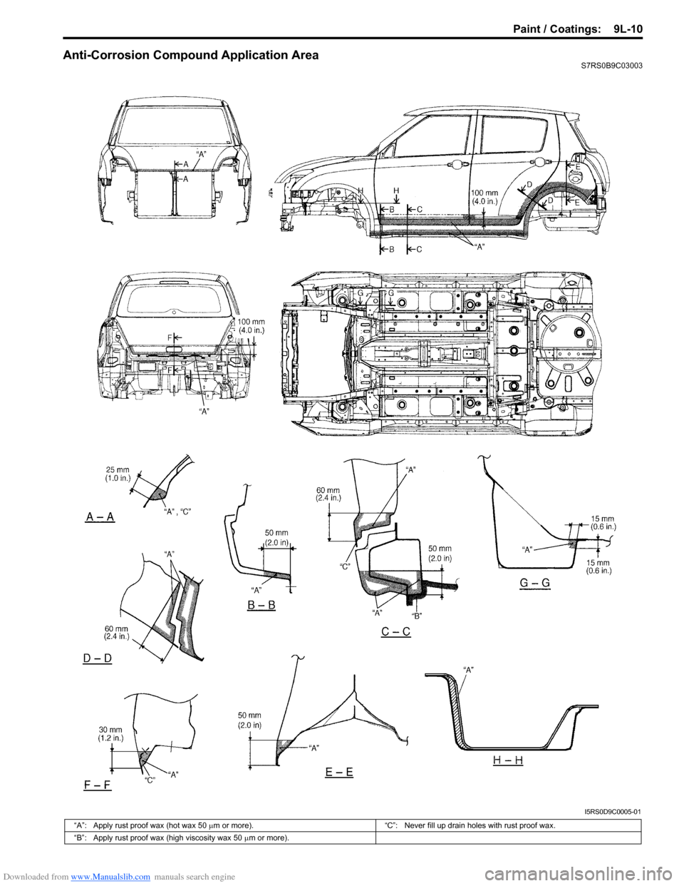
Anti-Corrosion Compound Application AreaS7RS0B9C03003
I5RS0D9C0005-01
“A”: Apply rust proof wax (hot wax 50 µm or more). “C”: Never fill up drain holes with rust proof wax.
“B”: Apply rust proof wax (high viscosity wax 50 µm or more).
Page 1398 of 1496
![SUZUKI SWIFT 2007 2.G Service Workshop Manual Downloaded from www.Manualslib.com manuals search engine 9M-1 Exterior Trim:
Body, Cab and Accessories
Exterior Trim
Repair Instructions
Roof Molding ComponentsS7RS0B9D06001
42
2
1
3
[A]
2
53 mm (2.0 SUZUKI SWIFT 2007 2.G Service Workshop Manual Downloaded from www.Manualslib.com manuals search engine 9M-1 Exterior Trim:
Body, Cab and Accessories
Exterior Trim
Repair Instructions
Roof Molding ComponentsS7RS0B9D06001
42
2
1
3
[A]
2
53 mm (2.0](/img/20/7607/w960_7607-1397.png)
Downloaded from www.Manualslib.com manuals search engine 9M-1 Exterior Trim:
Body, Cab and Accessories
Exterior Trim
Repair Instructions
Roof Molding ComponentsS7RS0B9D06001
42
2
1
3
[A]
2
53 mm (2.09 in.)
I6RS0C9D0001-01
[A]: Roof side weather-strip installation position
3. Roof molding clip (Push-in type)
: Install roof molding clip to specified position on body with epoxy adhesive applied.
1. Roof molding 4. Windshield side garnish
2. Roof side weather-strip
Page 1414 of 1496
Downloaded from www.Manualslib.com manuals search engine 10B-11 Body Electrical Control System:
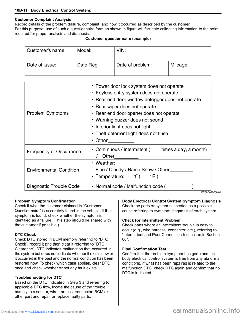
Customer Complaint Analysis
Record details of the problem (failure, complaint) and how it occurred as described by the customer.
For this purpose, use of such a questionnaire form as shown in figure will facilitate collectin g information to the point
required for proper analysis and diagnosis. Customer questionnaire (example)
Problem Symptom Confirmation
Check if what the custom er claimed in “Customer
Questionnaire” is accurately f ound in the vehicle. If that
symptom is found, check whether the symptom is
identified as a failure. (This step should be shared with
the customer if possible.)
DTC Check
Check DTC stored in BCM me mory referring to “DTC
Check”, record it and then clear it referring to “DTC
Clearance”. DTC indicates malfunction that occurred in
the system but does not indicate whether it exists now or
it occurred in the past and the normal condition has been
restored now. To check which case applies, clear DTC
once and check whether or not any fault exists.
Troubleshooting for DTC
Based on the DTC indicated in Step 3 and referring to
applicable DTC flow, locate the cause of the trouble,
namely in a sensor, wire harness, connector, BCM or
other part and repair or replace faulty parts. Body Electrical Control System Symptom Diagnosis
Check the parts or system
suspected as a possible
cause referring to symptom diagnosis of each system.
Check for Intermi ttent Problem
Check parts where an intermit tent trouble is easy to
occur (e.g., wire harness, connector, etc.), referring to
“Intermittent and Poor Connec tion Inspection in Section
00”.
Final Confirmation Test
Confirm that the problem symptom has gone and the
body electrical control system is free from any abnormal
conditions. If what has been repaired is related to the
malfunction DTC, check DTC again and confirm that no
DTC is indicated.
Customers name:
Model:
VIN:
Date of issue:
Date Reg:
Date of problem:
Mileage:
Problem Symptoms
Power door lock system does not operate
Keyless entry system does not operate
Rear end door window defogger does not operate
Rear wiper does not operate
Rear end door opener does not operate
Other
Frequency of Occurrence
Continuous / Intermittent ( times a day, a month)
/ Other
Environmental Condition
Weather:
Fine / Cloudy / Rain / Snow / Other
Temperature: (F )
Diagnostic Trouble Code Normal code / Malfunction code ( )
Warning buzzer does not sound
Interior light does not light
Theft deterrent light does not flush
I5RS0DA20006-01
Page 1415 of 1496
Downloaded from www.Manualslib.com manuals search engine Body Electrical Control System: 10B-12
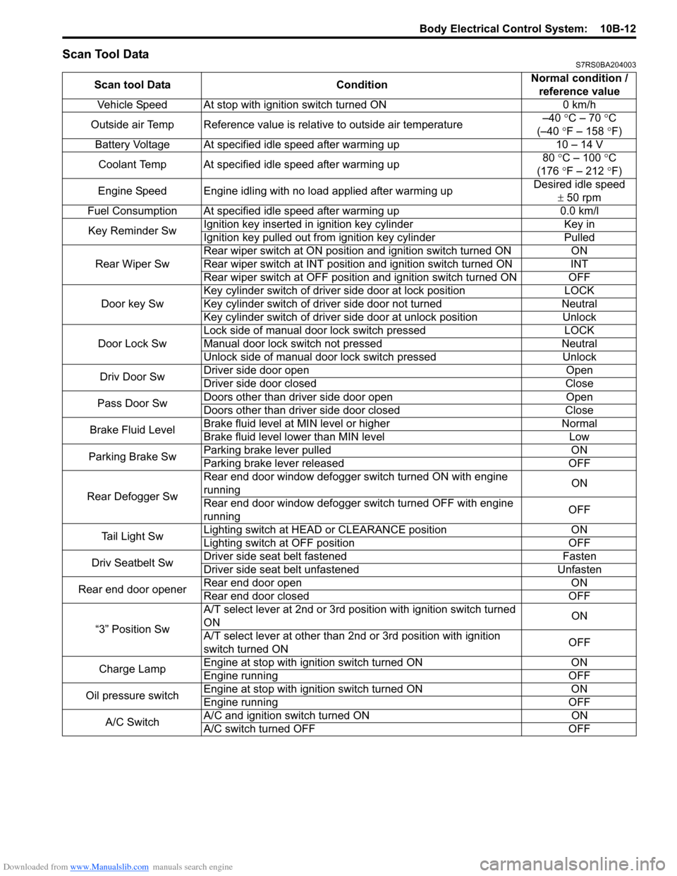
Scan Tool DataS7RS0BA204003
Scan tool DataConditionNormal condition /
reference value
Vehicle Speed At stop with ignition switch turned ON 0 km/h
Outside air Temp Reference value is relative to outside air temperature –40
°C – 70 °C
(–40 °F – 158 ° F)
Battery Voltage At specified idle speed after warming up 10 – 14 V
Coolant Temp At specified idle speed after warming up 80
°C – 100 ° C
(176 °F – 212 ° F)
Engine Speed Engine idling with no load applied after warming up Desired idle speed
± 50 rpm
Fuel Consumption At specified idle speed after warming up 0.0 km/l
Key Reminder Sw Ignition key inserted in
ignition key cylinder Key in
Ignition key pulled out from ignition key cylinder Pulled
Rear Wiper Sw Rear wiper switch at ON position and ignition switch turned ON
ON
Rear wiper switch at INT position and ignition switch turned ON INT
Rear wiper switch at OFF position and ignition switch turned ON OFF
Door key Sw Key cylinder switch of driver side door at lock position
LOCK
Key cylinder switch of driver side door not turned Neutral
Key cylinder switch of driver side door at unlock position Unlock
Door Lock Sw Lock side of manual door lock switch pressed
LOCK
Manual door lock switch not pressed Neutral
Unlock side of manual door lock switch pressed Unlock
Driv Door Sw Driver side door open
Open
Driver side door closed Close
Pass Door Sw Doors other than driver side door open
Open
Doors other than driver side door closed Close
Brake Fluid Level Brake fluid level at MIN level or higher
Normal
Brake fluid level lower than MIN level Low
Parking Brake Sw Parking brake lever pulled
ON
Parking brake lever released OFF
Rear Defogger Sw Rear end door window defogger switch turned ON with engine
running
ON
Rear end door window defogger switch turned OFF with engine
running OFF
Tail Light Sw Lighting switch at HEAD
or CLEARANCE position ON
Lighting switch at OFF position OFF
Driv Seatbelt Sw Driver side seat belt fastened
Fasten
Driver side seat belt unfastened Unfasten
Rear end door opener Rear end door open
ON
Rear end door closed OFF
“3” Position Sw A/T select lever at 2nd or 3rd position with ignition switch turned
ON
ON
A/T select lever at other than 2nd or 3rd position with ignition
switch turned ON OFF
Charge Lamp Engine at stop with ignition switch turned ON
ON
Engine running OFF
Oil pressure switch Engine at stop with ignition switch turned ON
ON
Engine running OFF
A/C Switch A/C and ignition switch turned ON
ON
A/C switch turned OFF OFF
Page 1435 of 1496
Downloaded from www.Manualslib.com manuals search engine Body Electrical Control System: 10B-32
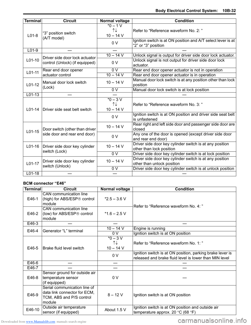
BCM connector “E46”L01-8
“3” position switch
(A/T model) *0 – 1 V
↑↓
10 – 14 V Refer to “Reference waveform No. 2: ”
0 V Ignition switch is at ON positi
on and A/T select lever is at
“2” or “3” position
L01-9 — — —
L01-10 Driver side door lock actuator
control (Unlock) (if equipped) 10 – 14 V Unlock signal is output for driver side door lock actuator.
0 V Unlock signal is not output for driver side door lock
actuator.
L01-11 Rear end door opener
actuator control 0 V Rear end door opener actuator is not in operation
10 – 14 V Rear end door opener actuator is in operation
L01-12 Manual door lock switch
(Lock) 10 – 14 V
Manual door lock switch is at any position other than lock
position
0 V Manual door lock swit ch is at lock position
L01-13 — — —
L01-14 Driver side seat belt switch *0 – 3 V
↑↓
10 – 14 V Refer to “Reference waveform No. 3: ”
0 V Ignition switch is at ON position and driver side seat belt
is unfastened
L01-15 Door switch (other than driver
side door and rear end door) 10 – 14 V
Rear right and left side door and passenger side door are
closed
0 V Any one of the door is opened (except driver side door
and rear end door)
L01-16 Driver side door key cylinder switch (Lock) 10 – 14 V
Driver side door key cylinder switch is at any position
other than lock position
0 V Driver side door key cylinder switch is at lock position
L01-17 Driver side door key cylinder
switch (Unlock) 10 – 14 V
Driver side door key cylinder switch is at any position
other than unlock position
0 V Driver side door key cylinder switch is at unlock position
L01-18 — — —
Terminal Circuit Normal voltage Condition
Terminal
CircuitNormal voltage Condition
E46-1 CAN communication line
(high) for ABS/ESP
® control
module *2.5 – 3.6 V
Refer to “Reference waveform No. 4: ”
E46-2 CAN communication line
(low) for ABS/ESP
® control
module *1.6 – 2.5 V
E46-3 — — —
E46-4 Generator “L” terminal 10 – 14 V Engine is running
0 V Ignition switch is at ON position
E46-5 Brake fluid level switch *0 – 3 V
↑↓
10 – 14 V Refer to “Reference waveform No. 1: ”
0 V Ignition switch is at ON position, parking brake lever is
released and brake fluid level is lower than MIN level
E46-6 — — —
E46-7 — — —
E46-8 Sensor ground for outside air
temperature sensor
(if equipped) 0 V
—
E46-9 Serial communication line of
data link connector for ECM,
TCM, ABS and
P/S control
module 8 – 12 V Ignition switch is at ON position
E46-10 Outside air temperature
sensor (if equipped) About 1.5 VIgnition switch is at ON position and outside air
temperature approx. 20
°C (68 °F)
Page 1444 of 1496
Downloaded from www.Manualslib.com manuals search engine 10C-1 Immobilizer Control System:
Control Systems
Immobilizer Control System
Precautions
Precautions in Diagnosing TroublesS7RS0BA300001
• Before confirming the diagnostic trouble code (DTC),
do not disconnect connector from ECM, battery cable
from battery, ground wire harness, or main fuse. Such
disconnection will erase DTC stored in ECM.
• DTC stored in ECM memory can be checked as well as cleared by using SUZUKI scan tool. Before using
SUZUKI scan tool, read its operator’s manual
carefully to know how to use it and what functions are
available.
• Be sure to read “Precautions for Electrical Circuit Service in Section 00” before inspection.
• Communication of ECM, BCM, keyless start control module (if equipped), ABS / ESP ® control module,
steering angle sensor (ESP ® model), combination
meter and TCM (A/T model) is established by CAN
(Controller Area Network). Therefore, handle CAN
communication lines with care referring to “Precaution
for CAN Communication System in Section 00”. For
CAN communication system, refer to description on
“CAN Communication System Description in Section
1A”.
Precaution in Replacing ECMS7RS0BA300002
• If ECM is replaced with new or used one without immobilizer control function , the engine will not be
started. In case of the above, check if the newly
installed ECM has immobilizer control function.
• After ECM is replaced with new one or used one, the transponder code in the transponder built in the
ignition key has to be registered with ECM. Or, the
engine cannot be started up. For the registration
procedure, refer to “Procedure after ECM
Replacement”.
Precautions in Handling Immobilizer Control
System
S7RS0BA300003
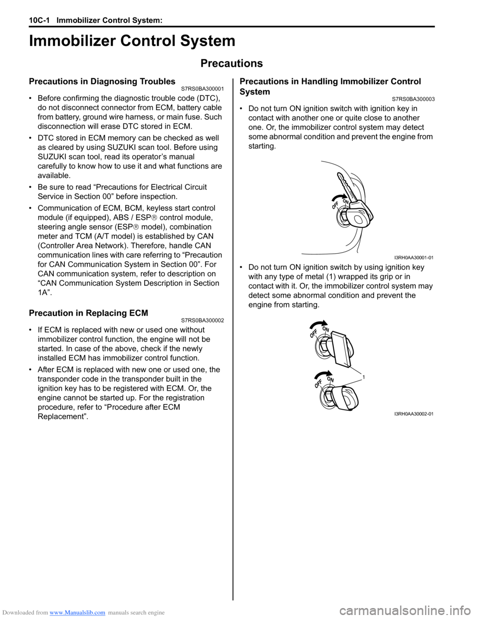
• Do not turn ON ignition sw itch with ignition key in
contact with another one or quite close to another
one. Or, the immobilizer co ntrol system may detect
some abnormal condition and prevent the engine from
starting.
• Do not turn ON ignition switch by using ignition key with any type of metal (1) wrapped its grip or in
contact with it. Or, the i mmobilizer control system may
detect some abnormal condition and prevent the
engine from starting.
I3RH0AA30001-01
1
I3RH0AA30002-01
Page 1448 of 1496
Downloaded from www.Manualslib.com manuals search engine 10C-5 Immobilizer Control System:
Diagnostic Information and Procedures
Immobilizer Control System CheckS7RS0BA304001
Diagnostic Trouble Code (DTC) CheckS7RS0BA304002
NOTE
To know how to use SUZUKI scan tool in
detail, refer to its operator’s manual.
Using Scan Tool
1) Turn the ignition switch to OFF position.
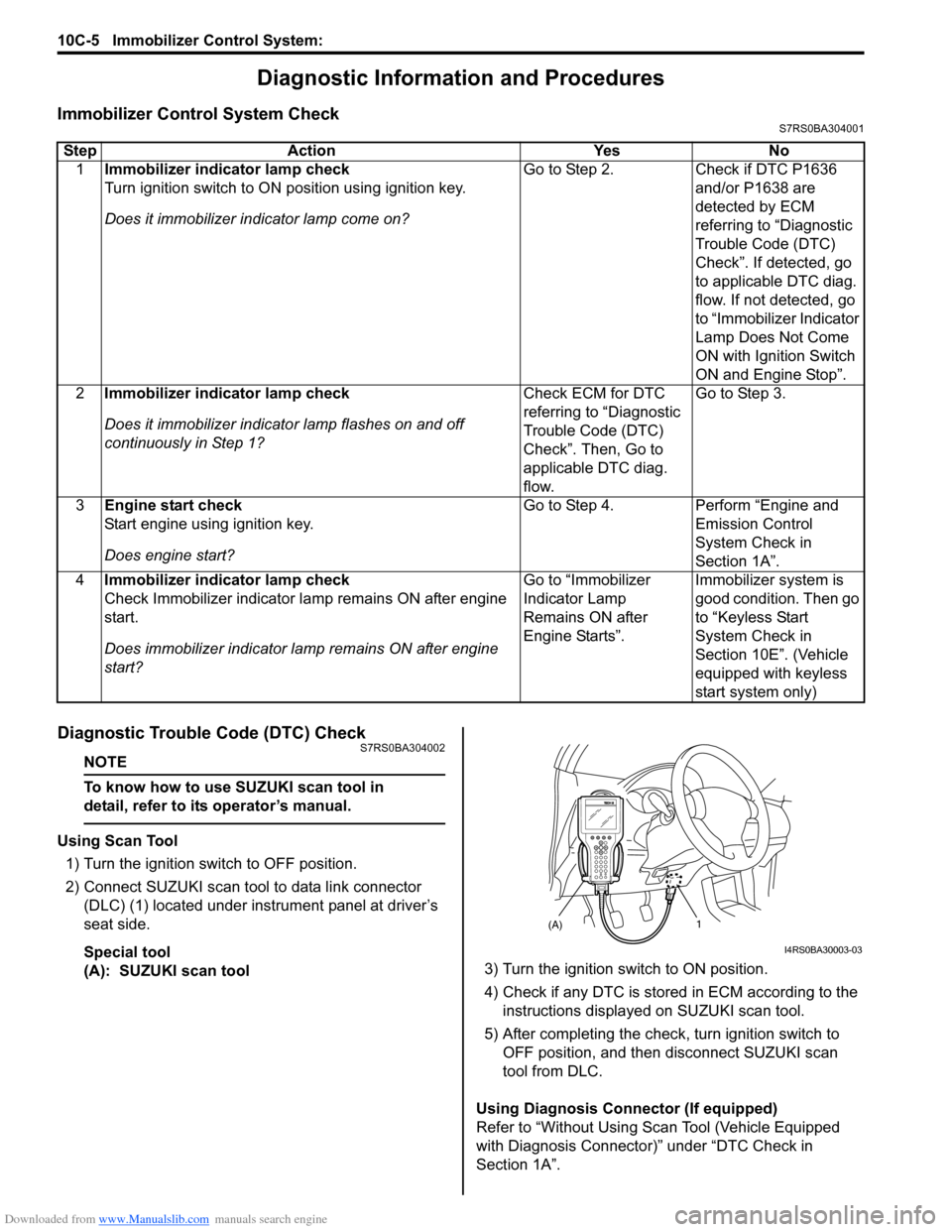
2) Connect SUZUKI scan tool to data link connector (DLC) (1) located under instrument panel at driver’s
seat side.
Special tool
(A): SUZUKI scan tool 3) Turn the ignition switch to ON position.
4) Check if any DTC is stored
in ECM according to the
instructions displayed on SUZUKI scan tool.
5) After completing the check, turn ignition switch to
OFF position, and then di sconnect SUZUKI scan
tool from DLC.
Using Diagnosis Connector (If equipped)
Refer to “Without Using Scan Tool (Vehicle Equipped
with Diagnosis Connector)” under “DTC Check in
Section 1A”.
Step Action Yes No
1 Immobilizer indicator lamp check
Turn ignition switch to ON position using ignition key.
Does it immobilizer in dicator lamp come on? Go to Step 2.
Check if DTC P1636
and/or P1638 are
detected by ECM
referring to “Diagnostic
Trouble Code (DTC)
Check”. If detected, go
to applicable DTC diag.
flow. If not detected, go
to “Immobilizer Indicator
Lamp Does Not Come
ON with Ignition Switch
ON and Engine Stop”.
2 Immobilizer indicator lamp check
Does it immobilizer indicato r lamp flashes on and off
continuously in Step 1? Check ECM for DTC
referring to “Diagnostic
Trouble Code (DTC)
Check”. Then, Go to
applicable DTC diag.
flow.Go to Step 3.
3 Engine start check
Start engine using ignition key.
Does engine start? Go to Step 4.
Perform “Engine and
Emission Control
System Check in
Section 1A”.
4 Immobilizer indicator lamp check
Check Immobilizer indicator la mp remains ON after engine
start.
Does immobilizer indicator la mp remains ON after engine
start? Go to “Immobilizer
Indicator Lamp
Remains ON after
Engine Starts”.
Immobilizer system is
good condition. Then go
to “Keyless Start
System Check in
Section 10E”. (Vehicle
equipped with keyless
start system only)
(A)1
I4RS0BA30003-03
Page 1450 of 1496
Downloaded from www.Manualslib.com manuals search engine 10C-7 Immobilizer Control System:
Scan Tool DataS7RS0BA304005
Scan Tool Data Definitions
NUMBER OF LEARNT KEY
0 – 4 PCS: The number of the transponder code in the transponder built in the ignition key that is registered with ECM
NOTE
A maximum of four transponder codes can be registered with ECM. Therefore, the maximal value
should be 4.
INPUT YEAR
20**: The year in which the transponder code in the transpon der built in the ignition key is registered with ECM
INPUT MONTH
1 – 12: The month in which the transponder code in the transpond er built in the ignition key is registered with ECM
Immobilizer Indicator Lamp Does Not Come ON with Ignition Switch ON and Engine StopS7RS0BA304006
Wiring Diagram
Refer to “Immobilizer Control System Wiring Circuit Diagram”.
Circuit Description
When the ignition switch is turned ON, ECM read the code by the coil antenna from ignition key. Then if the code in
transponder in the key match with the one registered with ECM, transmits indication ON signal of immobilizer indicator
lamp to combination meter in order to turn immobilizer indicator lamp on. And then, combination meter turns
immobilizer indicator lamp on. When th e engine starts to run and no malfunction is detected in the system, ECM
transmits immobilizer indi cator lamp indication OFF signal to combination meter in order to turn immobilizer indicator
lamp off. And then, comb ination meter turns immobilizer indicator lamp off, but if a malfunction was or is detected,
immobilizer indicator lamp is flashes ON and OF F, when ignition switch turn to ON position.
Troubleshooting Scan Tool Data Vehicl
e Condition Normal Data
NUMBER OF LEARNT KEY Ignition switch at ON position 0 – 4 INPUT YEAR Ignition switch at ON position 2005 or later
INPUT MONTH Ignition switch at ON position 1 – 12
Step Action YesNo
1 Immobilizer indicator lamp power supply check
1) Turn ignition switch to ON position.
Do other warning lights come ON? Go to Step 2.
Go to Step 4.
2 DTC check of ECM
1) Connect scan tool to DLC with ignition switch turned
OFF.
2) Turn ON ignition switch and check DTC.
Is DTC P1674, P1675, P1678 and/or P1685 detected? Go to applicable DTC
diag. flow.
Go to Step 3.
3 DTC check of BCM
1) Check BCM for DTC referring to “DTC Check in Section
10B”.
Is DTC U1073, U1100 and/or U1144 detected? Go to applicable DTC
diag. flow.
Substitute a known-
good combination meter
and recheck. If
immobilizer indicator
lamp still remains OFF,
substitute a known good
ECM and recheck.