low SUZUKI SWIFT 2007 2.G Service Workshop Manual
[x] Cancel search | Manufacturer: SUZUKI, Model Year: 2007, Model line: SWIFT, Model: SUZUKI SWIFT 2007 2.GPages: 1496, PDF Size: 34.44 MB
Page 824 of 1496
Downloaded from www.Manualslib.com manuals search engine 5B-10 Manual Transmission/Transaxle:
16) Remove engine under covers.
17) Support transaxle with transmission jack.
18) Remove transaxle to engine bolts and nut of lower side.
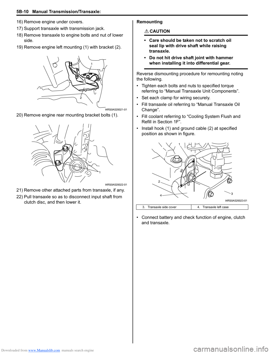
19) Remove engine left mounting (1) with bracket (2).
20) Remove engine rear mounting bracket bolts (1).
21) Remove other attached parts from transaxle, if any.
22) Pull transaxle so as to disconnect input shaft from clutch disc, and then lower it. Remounting
CAUTION!
• Care should be taken not to scratch oil
seal lip with drive shaft while raising
transaxle.
• Do not hit drive shaft joint with hammer when installing it into differential gear.
Reverse dismounting procedure for remounting noting
the following.
• Tighten each bolts and nuts to specified torque referring to “Manual Transaxle Unit Components”.
• Set each clamp for wiring securely.
• Fill transaxle oil referring to “Manual Transaxle Oil
Change”.
• Fill coolant referring to “Cooling System Flush and
Refill in Section 1F”.
• Install hook (1) and ground cable (2) at specified position as shown in figure.
• Connect battery and check function of engine, clutch
and transaxle.
1
2
I4RS0A520021-01
1
I4RS0A520022-01
3. Transaxle side cover 4. Transaxle left case
90
1
2 3
4
I4RS0A520023-01
Page 826 of 1496
Downloaded from www.Manualslib.com manuals search engine 5B-12 Manual Transmission/Transaxle:
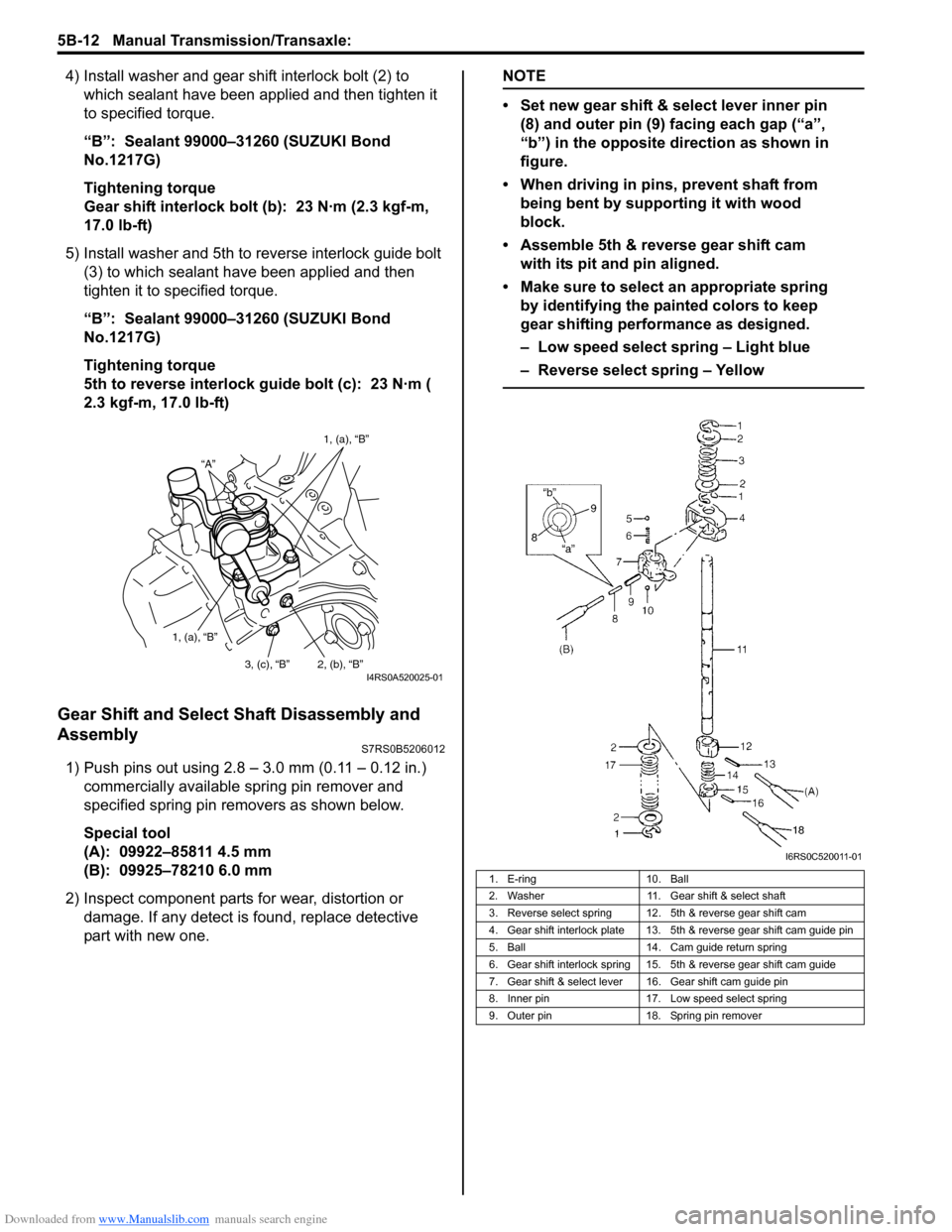
4) Install washer and gear shift interlock bolt (2) to which sealant have been app lied and then tighten it
to specified torque.
“B”: Sealant 99000–31260 (SUZUKI Bond
No.1217G)
Tightening torque
Gear shift interlock bolt (b): 23 N·m (2.3 kgf-m,
17.0 lb-ft)
5) Install washer and 5th to reverse interlock guide bolt (3) to which sealant have been applied and then
tighten it to specified torque.
“B”: Sealant 99000–31260 (SUZUKI Bond
No.1217G)
Tightening torque
5th to reverse interlock guide bolt (c): 23 N·m (
2.3 kgf-m, 17.0 lb-ft)
Gear Shift and Select Shaft Disassembly and
Assembly
S7RS0B5206012
1) Push pins out using 2.8 – 3.0 mm (0.11 – 0.12 in.) commercially available spring pin remover and
specified spring pin removers as shown below.
Special tool
(A): 09922–85811 4.5 mm
(B): 09925–78210 6.0 mm
2) Inspect component parts for wear, distortion or
damage. If any detect is found, replace detective
part with new one.
NOTE
• Set new gear shift & select lever inner pin (8) and outer pin (9) facing each gap (“a”,
“b”) in the opposite direction as shown in
figure.
• When driving in pins, prevent shaft from being bent by supporting it with wood
block.
• Assemble 5th & reverse gear shift cam with its pit and pin aligned.
• Make sure to select an appropriate spring by identifying the painted colors to keep
gear shifting performance as designed.
– Low speed select spring – Light blue
– Reverse select spring – Yellow
“A” 1, (a), “B”
1, (a), “B” 2, (b), “B”
3, (c), “B”
I4RS0A520025-01
1. E-ring 10. Ball
2. Washer 11. Gear shift & select shaft
3. Reverse select spring 12. 5th & reverse gear shift cam
4. Gear shift interlock plate 13. 5th & reverse gear shift cam guide pin
5. Ball 14. Cam guide return spring
6. Gear shift interlock spring 15. 5th & reverse gear shift cam guide
7. Gear shift & select lever 16. Gear shift cam guide pin
8. Inner pin 17. Low speed select spring
9. Outer pin 18. Spring pin remover
I6RS0C520011-01
Page 829 of 1496
Downloaded from www.Manualslib.com manuals search engine Manual Transmission/Transaxle: 5B-15
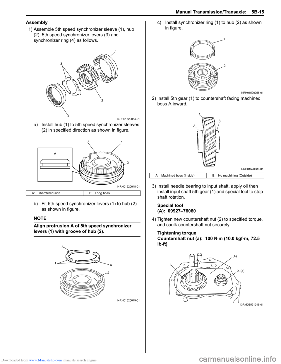
Assembly1) Assemble 5th speed synchronizer sleeve (1), hub (2), 5th speed synchronizer levers (3) and
synchronizer ring (4) as follows.
a) Install hub (1) to 5th speed synchronizer sleeves (2) in specified direction as shown in figure.
b) Fit 5th speed synchronizer levers (1) to hub (2) as shown in figure.
NOTE
Align protrusion A of 5th speed synchronizer
levers (1) with groove of hub (2).
c) Install synchronizer ring (1) to hub (2) as shown in figure.
2) Install 5th gear (1) to countershaft facing machined boss A inward.
3) Install needle bearing to input shaft, apply oil then install input shaft 5th gear (1) and special tool to stop
shaft rotation.
Special tool
(A): 09927–76060
4) Tighten new countershaft nut (2) to specified torque, and caulk countershaft nut securely.
Tightening torque
Countershaft nut (a): 100 N·m (10.0 kgf-m, 72.5
lb-ft)
A: Chamfered side B: Long boss
I4RH01520054-01
1
2
B
A
I4RH01520048-01
1A
2
A
I4RH01520049-01
A: Machined boss (Inside)
B: No machining (Outside)
1
2
I4RH01520055-01
I2RH01520088-01
1
(A)
2, (a)
I3RM0B521016-01
Page 831 of 1496
Downloaded from www.Manualslib.com manuals search engine Manual Transmission/Transaxle: 5B-17
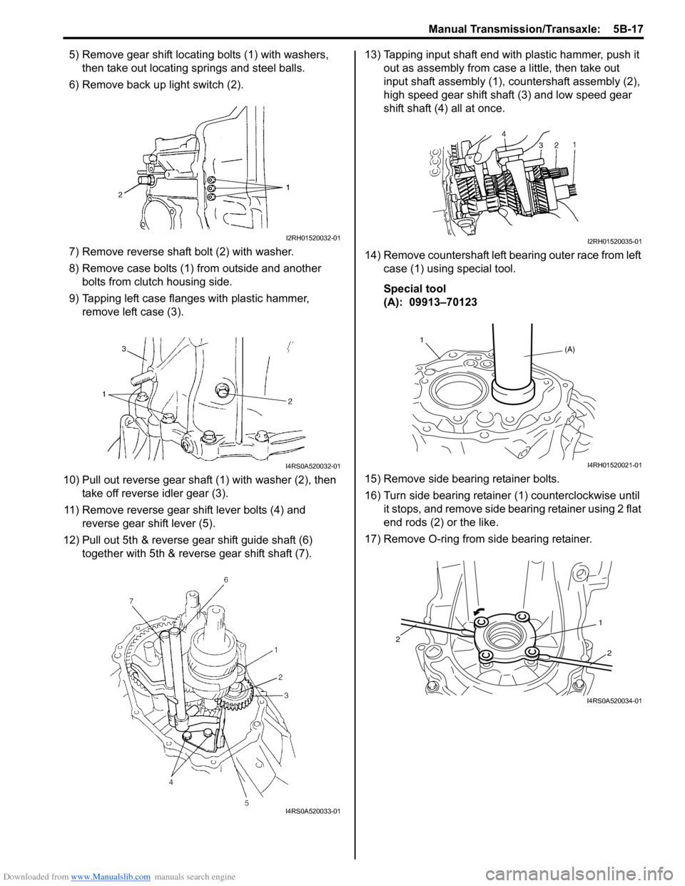
5) Remove gear shift locating bolts (1) with washers,
then take out locating springs and steel balls.
6) Remove back up light switch (2).
7) Remove reverse shaft bolt (2) with washer.
8) Remove case bolts (1) from outside and another bolts from clutch housing side.
9) Tapping left case flanges with plastic hammer, remove left case (3).
10) Pull out reverse gear shaft (1) with washer (2), then take off reverse idler gear (3).
11) Remove reverse gear shift lever bolts (4) and reverse gear shift lever (5).
12) Pull out 5th & reverse gear shift guide shaft (6) together with 5th & reverse gear shift shaft (7). 13) Tapping input shaft end with plastic hammer, push it
out as assembly from case a little, then take out
input shaft assembly (1), countershaft assembly (2),
high speed gear shift shaft (3) and low speed gear
shift shaft (4) all at once.
14) Remove countershaft left bearing outer race from left case (1) using special tool.
Special tool
(A): 09913–70123
15) Remove side bearing retainer bolts.
16) Turn side bearing retainer (1) counterclockwise until it stops, and remove side bearing retainer using 2 flat
end rods (2) or the like.
17) Remove O-ring from side bearing retainer.
I2RH01520032-01
I4RS0A520032-01
I4RS0A520033-01
I2RH01520035-01
(A)
1
I4RH01520021-01
1
2
2
I4RS0A520034-01
Page 832 of 1496
Downloaded from www.Manualslib.com manuals search engine 5B-18 Manual Transmission/Transaxle:
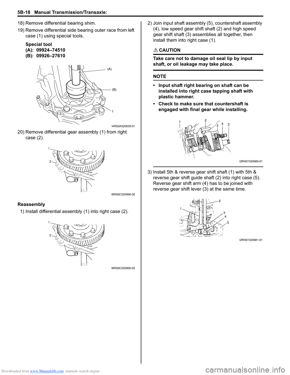
18) Remove differential bearing shim.
19) Remove differential side bearing outer race from left case (1) using special tools.
Special tool
(A): 09924–74510
(B): 09926–27610
20) Remove differential gear assembly (1) from right case (2).
Reassembly 1) Install differential assembly (1) into right case (2). 2) Join input shaft assembly (5), countershaft assembly
(4), low speed gear shift shaft (2) and high speed
gear shift shaft (3) assemblies all together, then
install them into right case (1).
CAUTION!
Take care not to damage oil seal lip by input
shaft, or oil leakage may take place.
NOTE
• Input shaft right bearing on shaft can be
installed into right case tapping shaft with
plastic hammer.
• Check to make sure that countershaft is engaged with final g ear while installing.
3) Install 5th & reverse gear shift shaft (1) with 5th &
reverse gear shift guide shaft (2) into right case (5).
Reverse gear shift arm (4) has to be joined with
reverse gear shift lever (3) at the same time.
(A)
(B)
1
I4RS0A520035-01
I6RS0C520006-02
I6RS0C520006-02
I2RH01520080-01
I2RH01520081-01
Page 834 of 1496
Downloaded from www.Manualslib.com manuals search engine 5B-20 Manual Transmission/Transaxle:
9) Install side bearing retainer as follows.a) Install differential side bearing outer race to left case and then tap and accustom outer race
using special tool and plastic hammer.
CAUTION!
Do not drive in a race with hammer.
Driving it may cause to damage bearing.
Special tool
(A): 09926–27610
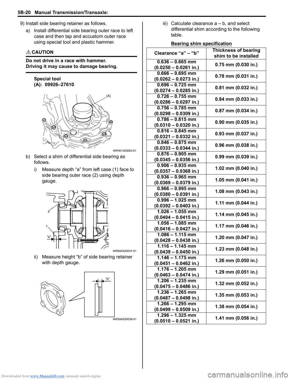
b) Select a shim of differential side bearing as follows.
i) Measure depth “a” from left case (1) face to side bearing outer race (2) using depth
gauge.
ii) Measure height “b” of side bearing retainer with depth gauge. iii) Calculate clearance a – b, and select
differential shim acco rding to the following
table.
Bearing shim specification
(A)
I4RH01520053-01
I4RS0A520037-01
“b”
I4RS0A520038-01
Clearance “a” – “b” Thickness of bearing
shim to be installed
0.636 – 0.665 mm
(0.0250 – 0.0261 in.) 0.75 mm (0.030 in.)
0.666 – 0.695 mm
(0.0262 – 0.0273 in.) 0.78 mm (0.031 in.)
0.696 – 0.725 mm
(0.0274 – 0.0285 in.) 0.81 mm (0.032 in.)
0.726 – 0.755 mm
(0.0286 – 0.0297 in.) 0.84 mm (0.033 in.)
0.756 – 0.785 mm
(0.0298 – 0.0309 in.) 0.87 mm (0.034 in.)
0.786 – 0.815 mm
(0.0310 – 0.0320 in.) 0.90 mm (0.035 in.)
0.816 – 0.845 mm
(0.0321 – 0.0332 in.) 0.93 mm (0.037 in.)
0.846 – 0.875 mm
(0.0333 – 0.0344 in.) 0.96 mm (0.038 in.)
0.876 – 0.905 mm
(0.0345 – 0.0356 in.) 0.99 mm (0.039 in.)
0.906 – 0.935 mm
(0.0357 – 0.0368 in.) 1.02 mm (0.040 in.)
0.936 – 0.965 mm
(0.0369 – 0.0379 in.) 1.05 mm (0.041 in.)
0.966 – 0.995 mm
(0.0380 – 0.0391 in.) 1.08 mm (0.043 in.)
0.996 – 1.025 mm
(0.0392 – 0.0403 in.) 1.11 mm (0.044 in.)
1.026 – 1.055 mm
(0.0404 – 0.0415 in.) 1.14 mm (0.045 in.)
1.056 – 1.085 mm
(0.0416 – 0.0427 in.) 1.17 mm (0.046 in.)
1.086 – 1.115 mm
(0.0428 – 0.0438 in.) 1.20 mm (0.047 in.)
1.116 – 1.145 mm
(0.0439 – 0.0450 in.) 1.23 mm (0.048 in.)
1.146 – 1.175 mm
(0.0451 – 0.0462 in.) 1.26 mm (0.050 in.)
1.176 – 1.205 mm
(0.0463 – 0.0474 in.) 1.29 mm (0.051 in.)
1.206 – 1.235 mm
(0.0475 – 0.0486 in.) 1.32 mm (0.052 in.)
1.236 – 1.265 mm
(0.0487 – 0.0498 in.) 1.35 mm (0.053 in.)
1.266 – 1.295 mm
(0.0499 – 0.0509 in.) 1.38 mm (0.054 in.)
1.296 – 1.325 mm
(0.0510 – 0.0521 in.) 1.41 mm (0.056 in.)
Page 835 of 1496
Downloaded from www.Manualslib.com manuals search engine Manual Transmission/Transaxle: 5B-21
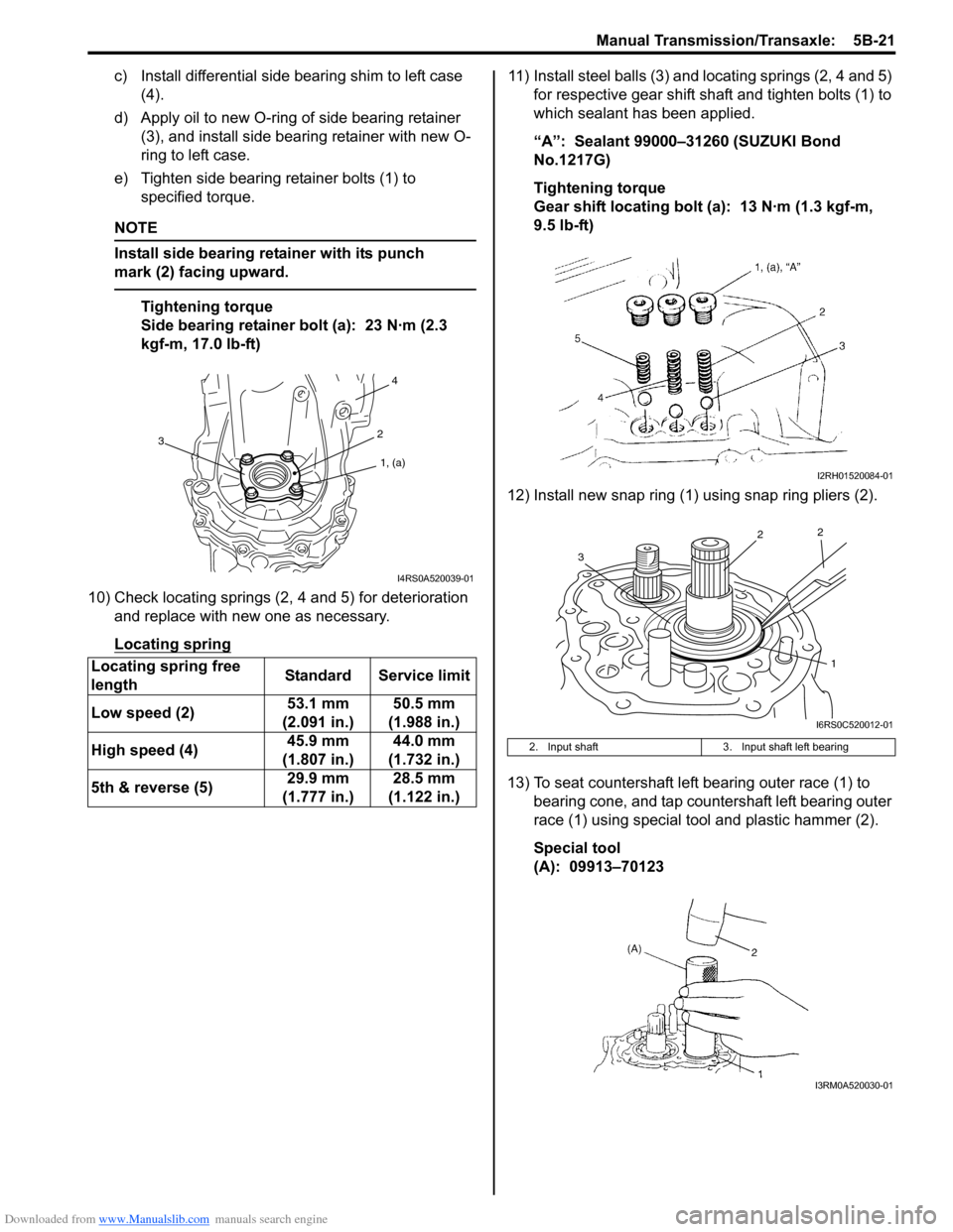
c) Install differential side bearing shim to left case (4).
d) Apply oil to new O-ring of side bearing retainer (3), and install side bea ring retainer with new O-
ring to left case.
e) Tighten side bearing retainer bolts (1) to specified torque.
NOTE
Install side bearing retainer with its punch
mark (2) facing upward.
Tightening torque
Side bearing retainer bolt (a): 23 N·m (2.3
kgf-m, 17.0 lb-ft)
10) Check locating springs (2, 4 and 5) for deterioration and replace with new one as necessary.
Locating spring
11) Install steel balls (3) and locating springs (2, 4 and 5) for respective gear shift shaft and tighten bolts (1) to
which sealant has been applied.
“A”: Sealant 99000–31260 (SUZUKI Bond
No.1217G)
Tightening torque
Gear shift locating bolt (a): 13 N·m (1.3 kgf-m,
9.5 lb-ft)
12) Install new snap ring (1) using snap ring pliers (2).
13) To seat countershaft left bearing outer race (1) to bearing cone, and tap countershaft left bearing outer
race (1) using special tool and plastic hammer (2).
Special tool
(A): 09913–70123
Locating spring free
length
Standard Service limit
Low speed (2) 53.1 mm
(2.091 in.) 50.5 mm
(1.988 in.)
High speed (4) 45.9 mm
(1.807 in.) 44.0 mm
(1.732 in.)
5th & reverse (5) 29.9 mm
(1.777 in.) 28.5 mm
(1.122 in.)
1, (a)
2
4
3
I4RS0A520039-01
2. Input shaft 3. Input shaft left bearing
I2RH01520084-01
1
2
2
3
I6RS0C520012-01
I3RM0A520030-01
Page 839 of 1496
Downloaded from www.Manualslib.com manuals search engine Manual Transmission/Transaxle: 5B-25
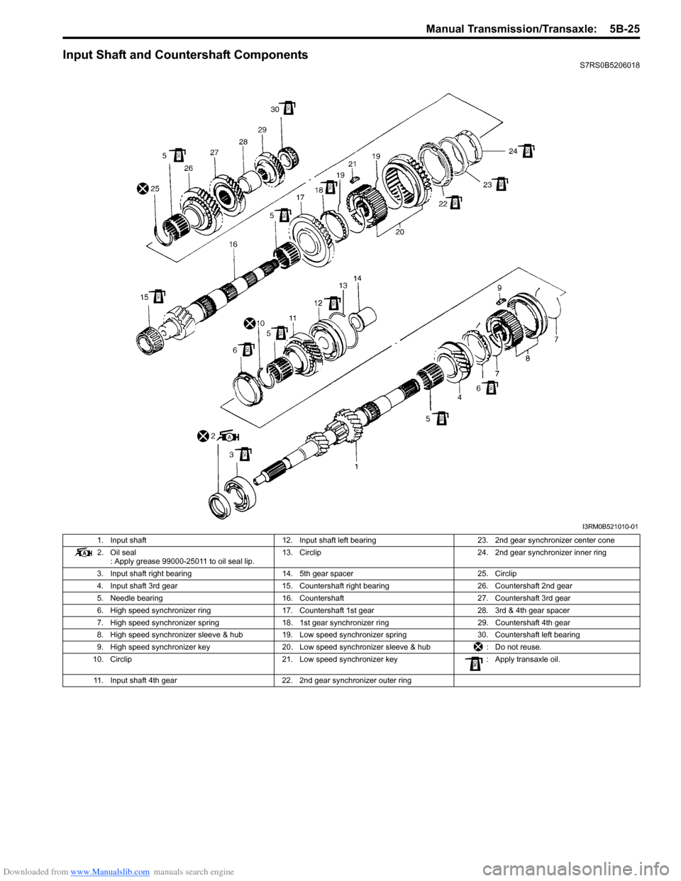
Input Shaft and Countershaft ComponentsS7RS0B5206018
I3RM0B521010-01
1. Input shaft12. Input shaft left bearing 23. 2nd gear synchronizer center cone
2. Oil seal : Apply grease 99000-25011 to oil seal lip. 13. Circlip
24. 2nd gear synchronizer inner ring
3. Input shaft right bearing 14. 5th gear spacer 25. Circlip
4. Input shaft 3rd gear 15. Countershaft right bearing 26. Countershaft 2nd gear
5. Needle bearing 16. Countershaft 27. Countershaft 3rd gear
6. High speed synchronizer ring 17. Countershaft 1st gear 28. 3rd & 4th gear spacer
7. High speed synchronizer spring 18. 1st gear synchronizer ring 29. Countershaft 4th gear
8. High speed synchronizer sleeve & hub 19. Low speed synchronizer spring 30. Countershaft left bearing
9. High speed synchronizer key 20. Low speed synchronizer sleeve & hub : Do not reuse.
10. Circlip 21. Low speed synchronizer key : Apply transaxle oil.
11. Input shaft 4th gear 22. 2nd gear synchronizer outer ring
Page 840 of 1496
Downloaded from www.Manualslib.com manuals search engine 5B-26 Manual Transmission/Transaxle:
Input Shaft Assembly Disassembly and
Reassembly
S7RS0B5206019
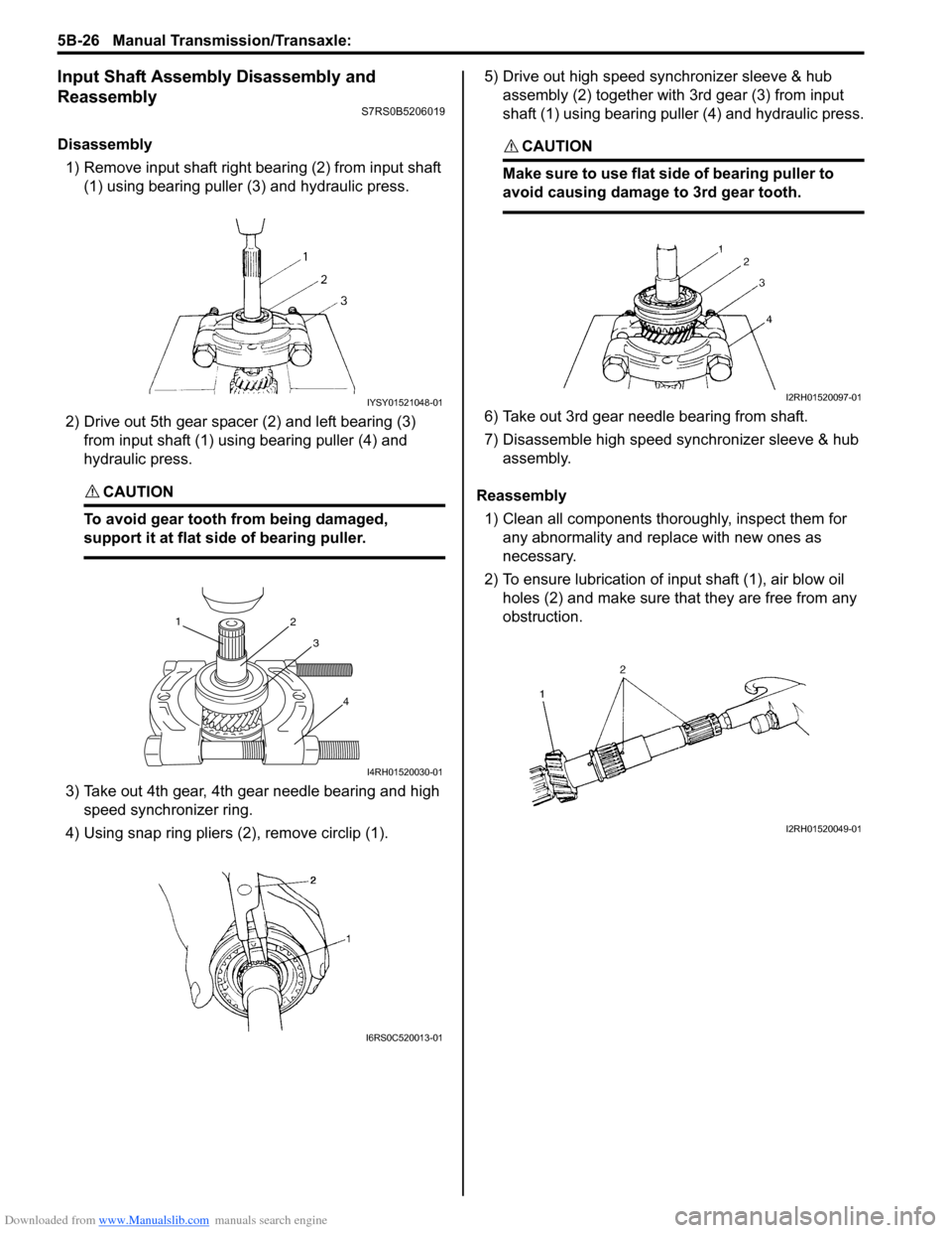
Disassembly1) Remove input shaft right bearing (2) from input shaft (1) using bearing puller (3) and hydraulic press.
2) Drive out 5th gear spacer (2) and left bearing (3) from input shaft (1) using bearing puller (4) and
hydraulic press.
CAUTION!
To avoid gear tooth from being damaged,
support it at flat side of bearing puller.
3) Take out 4th gear, 4th gear needle bearing and high speed synchronizer ring.
4) Using snap ring pliers (2), remove circlip (1). 5) Drive out high speed synchronizer sleeve & hub
assembly (2) together with 3rd gear (3) from input
shaft (1) using bearing puller (4) and hydraulic press.
CAUTION!
Make sure to use flat side of bearing puller to
avoid causing damage to 3rd gear tooth.
6) Take out 3rd gear needle bearing from shaft.
7) Disassemble high speed synchronizer sleeve & hub assembly.
Reassembly 1) Clean all components thoroughly, inspect them for any abnormality and replace with new ones as
necessary.
2) To ensure lubrication of input shaft (1), air blow oil holes (2) and make sure that they are free from any
obstruction.
IYSY01521048-01
1 2
3
4
I4RH01520030-01
I6RS0C520013-01
I2RH01520097-01
I2RH01520049-01
Page 841 of 1496
Downloaded from www.Manualslib.com manuals search engine Manual Transmission/Transaxle: 5B-27
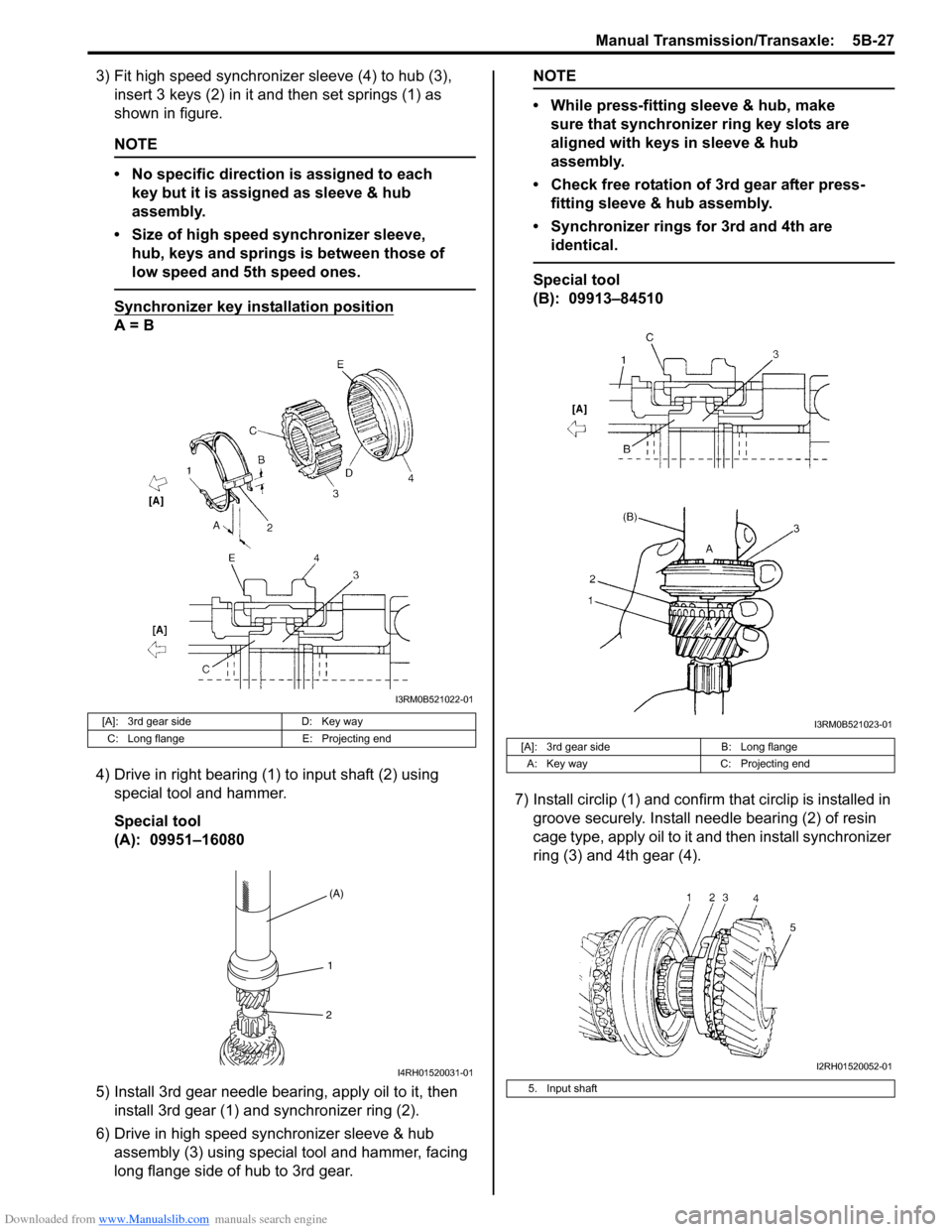
3) Fit high speed synchronizer sleeve (4) to hub (3), insert 3 keys (2) in it and then set springs (1) as
shown in figure.
NOTE
• No specific direction is assigned to each key but it is assigned as sleeve & hub
assembly.
• Size of high speed synchronizer sleeve, hub, keys and springs is between those of
low speed and 5th speed ones.
Synchronizer key in stallation position
A = B
4) Drive in right bearing (1) to input shaft (2) using special tool and hammer.
Special tool
(A): 09951–16080
5) Install 3rd gear needle bearing, apply oil to it, then install 3rd gear (1) and synchronizer ring (2).
6) Drive in high speed synchronizer sleeve & hub assembly (3) using special tool and hammer, facing
long flange side of hub to 3rd gear.
NOTE
• While press-fitting sleeve & hub, make sure that synchronizer ring key slots are
aligned with keys in sleeve & hub
assembly.
• Check free rotation of 3rd gear after press- fitting sleeve & hub assembly.
• Synchronizer rings for 3rd and 4th are identical.
Special tool
(B): 09913–84510
7) Install circlip (1) and confirm that circlip is installed in
groove securely. Install needle bearing (2) of resin
cage type, apply oil to it and then install synchronizer
ring (3) and 4th gear (4).
[A]: 3rd gear side D: Key way
C: Long flange E: Projecting end
I3RM0B521022-01
(A)
1
2
I4RH01520031-01
[A]: 3rd gear side B: Long flange
A: Key way C: Projecting end
5. Input shaft
I3RM0B521023-01
I2RH01520052-01