1400 SUZUKI SWIFT 2007 2.G Service Repair Manual
[x] Cancel search | Manufacturer: SUZUKI, Model Year: 2007, Model line: SWIFT, Model: SUZUKI SWIFT 2007 2.GPages: 1496, PDF Size: 34.44 MB
Page 344 of 1496
Downloaded from www.Manualslib.com manuals search engine 1D-59 Engine Mechanical:
Main Bearings InspectionS7RS0B1406038
General Information
• Service main bearings are available in standard size and 0.25 mm (0.0098 in.) undersize, and each of them
has 5 kinds of bearings differing in tolerance.
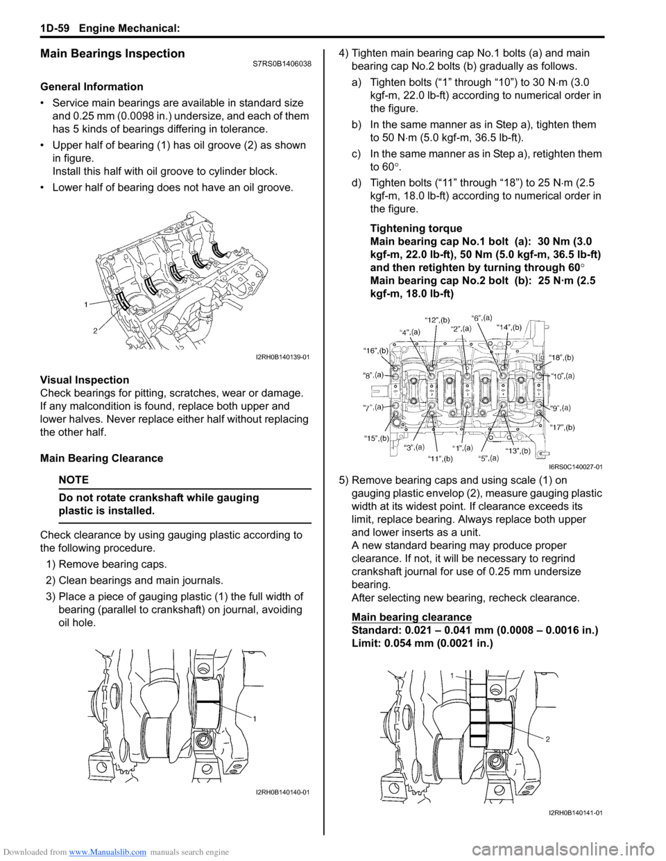
• Upper half of bearing (1) has oil groove (2) as shown in figure.
Install this half with o il groove to cylinder block.
• Lower half of bearing does not have an oil groove.
Visual Inspection
Check bearings for pitting, scratches, wear or damage.
If any malcondition is foun d, replace both upper and
lower halves. Never replace either half without replacing
the other half.
Main Bearing Clearance
NOTE
Do not rotate crankshaft while gauging
plastic is installed.
Check clearance by using ga uging plastic according to
the following procedure.
1) Remove bearing caps.
2) Clean bearings and main journals.
3) Place a piece of gauging plastic (1) the full width of bearing (parallel to crankshaft) on journal, avoiding
oil hole. 4) Tighten main bearing cap No.1 bolts (a) and main
bearing cap No.2 bolts (b) gradually as follows.
a) Tighten bolts (“1” through “10”) to 30 N ⋅m (3.0
kgf-m, 22.0 lb-ft) according to numerical order in
the figure.
b) In the same manner as in Step a), tighten them to 50 N ⋅m (5.0 kgf-m, 36.5 lb-ft).
c) In the same manner as in Step a), retighten them to 60 °.
d) Tighten bolts (“11” through “18”) to 25 N ⋅m (2.5
kgf-m, 18.0 lb-ft) according to numerical order in
the figure.
Tightening torque
Main bearing cap No.1 bolt (a): 30 Nm (3.0
kgf-m, 22.0 lb-ft), 50 Nm (5.0 kgf-m, 36.5 lb-ft)
and then retighten by turning through 60°
Main bearing cap No.2 bolt (b): 25 N·m (2.5
kgf-m, 18.0 lb-ft)
5) Remove bearing caps and using scale (1) on gauging plastic envelop (2), measure gauging plastic
width at its widest point. If clearance exceeds its
limit, replace bearing. Always replace both upper
and lower inserts as a unit.
A new standard bearing may produce proper
clearance. If not, it will be necessary to regrind
crankshaft journal for use of 0.25 mm undersize
bearing.
After selecting new bearing, recheck clearance.
Main bearing clearance
Standard: 0.021 – 0.041 mm (0.0008 – 0.0016 in.)
Limit: 0.054 mm (0.0021 in.)
I2RH0B140139-01
I2RH0B140140-01
I6RS0C140027-01
I2RH0B140141-01
Page 348 of 1496
Downloaded from www.Manualslib.com manuals search engine 1D-63 Engine Mechanical:
Main Bearing Cap No.1 Bolt
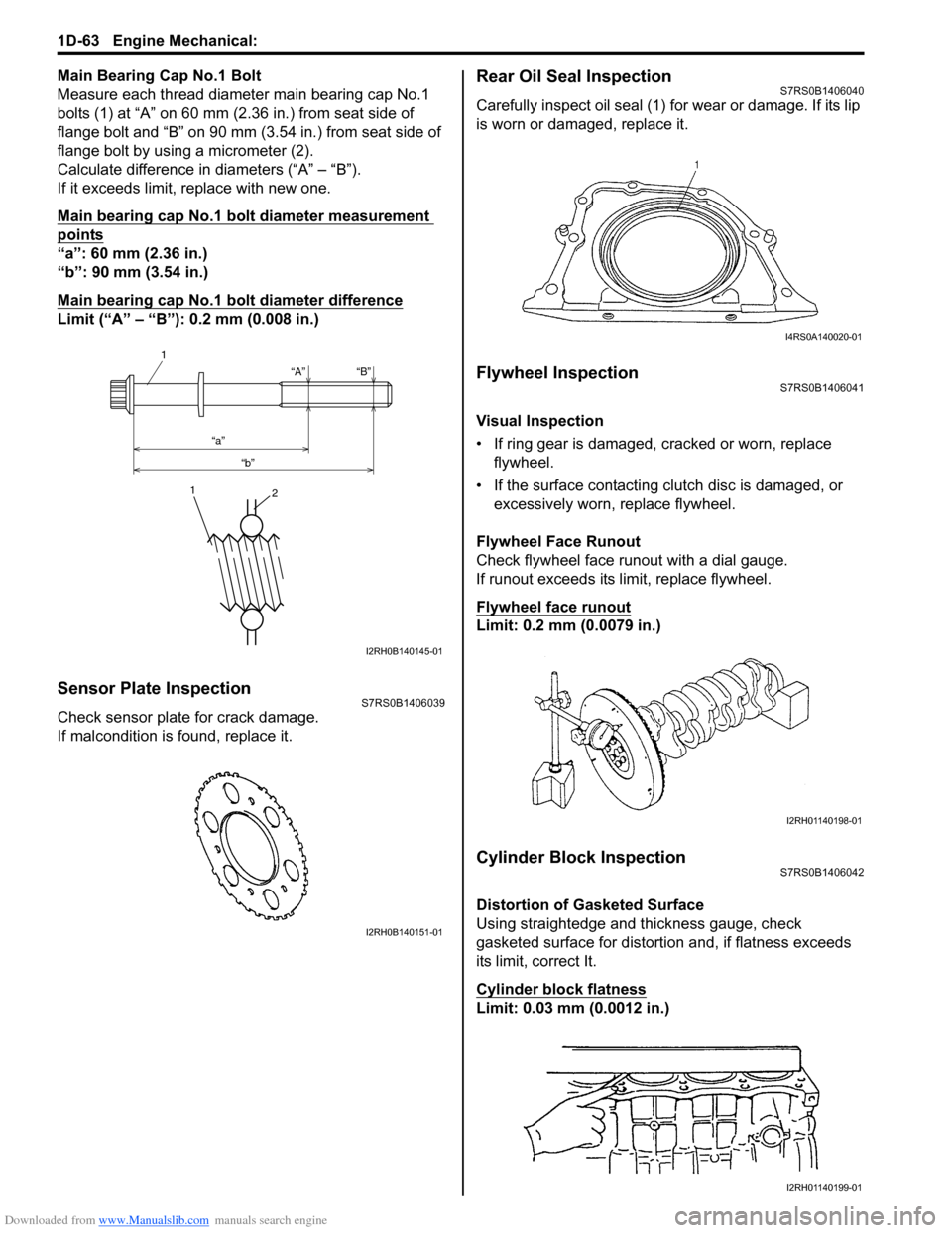
Measure each thread diameter main bearing cap No.1
bolts (1) at “A” on 60 mm (2.36 in.) from seat side of
flange bolt and “B” on 90 mm (3.54 in.) from seat side of
flange bolt by using a micrometer (2).
Calculate difference in diameters (“A” – “B”).
If it exceeds limit, replace with new one.
Main bearing cap No.1 bolt diameter measurement
points
“a”: 60 mm (2.36 in.)
“b”: 90 mm (3.54 in.)
Main bearing cap No.1 bolt diameter difference
Limit (“A” – “B”): 0.2 mm (0.008 in.)
Sensor Plate InspectionS7RS0B1406039
Check sensor plate for crack damage.
If malcondition is found, replace it.
Rear Oil Seal InspectionS7RS0B1406040
Carefully inspect oil seal (1) for wear or damage. If its lip
is worn or damaged, replace it.
Flywheel InspectionS7RS0B1406041
Visual Inspection
• If ring gear is damaged, cracked or worn, replace flywheel.
• If the surface contacting cl utch disc is damaged, or
excessively worn, replace flywheel.
Flywheel Face Runout
Check flywheel face runout with a dial gauge.
If runout exceeds its limit, replace flywheel.
Flywheel face runout
Limit: 0.2 mm (0.0079 in.)
Cylinder Block InspectionS7RS0B1406042
Distortion of Gasketed Surface
Using straightedge and thickness gauge, check
gasketed surface for distortion and, if flatness exceeds
its limit, correct It.
Cylinder block flatness
Limit: 0.03 mm (0.0012 in.)
“A”
“a” “b” “B”
1
1
2
I2RH0B140145-01
I2RH0B140151-01
I4RS0A140020-01
I2RH01140198-01
I2RH01140199-01
Page 955 of 1496
Downloaded from www.Manualslib.com manuals search engine Air Conditioning System: Manual Type 7B-7
Diagnostic Information and Procedures
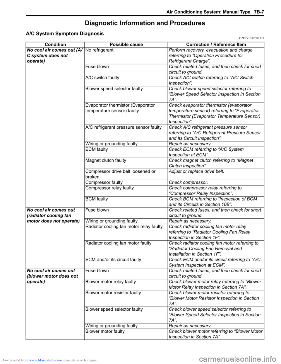
A/C System Symptom DiagnosisS7RS0B7214001
ConditionPossible cause Correction / Reference Item
No cool air comes out (A/
C system does not
operate) No refrigerant
Perform recovery, evacuation and charge
referring to “Operation Procedure for
Refrigerant Charge”.
Fuse blown Check related fuses, and then check for short
circuit to ground.
A/C switch faulty Check A/C switch referring to “A/C Switch
Inspection”.
Blower speed selector faulty Check blower speed selector referring to
“Blower Speed Selector Inspection in Section
7A”.
Evaporator thermistor (Evaporator
temperature sensor) faulty Check evaporator thermistor (evaporator
temperature sensor) referring to “Evaporator
Thermistor (Evaporator Temperature Sensor)
Inspection”.
A/C refrigerant pressure sensor faulty Check A/C refrigerant pressure sensor
referring to “A/C Refrigerant Pressure Sensor
and Its Circuit Inspection”.
Wiring or grounding faulty Repair as necessary.
ECM faulty Check ECM referring to “A/C System
Inspection at ECM”.
Magnet clutch faulty Check magnet clutch referring to “Magnet
Clutch Inspection”.
Compressor drive belt loosened or
broken Adjust or replace drive belt.
Compressor faulty Check compressor.
Compressor relay faulty Check compressor relay referring to
“Compressor Relay Inspection”.
BCM faulty Check BCM referring to “Inspection of BCM
and its Circuits in Section 10B”.
No cool air comes out
(radiator cooling fan
motor does not operate) Fuse blown
Check related fuses, and then check for short
circuit to ground.
Wiring or grounding faulty Repair as necessary.
Radiator cooling fan motor relay faulty Check radiator cooling fan motor relay
referring to “Radiator Cooling Fan Relay
Inspection in Section 1F”.
Radiator cooling fan motor faulty Check radiator cooling fan motor referring to
“Radiator Cooling Fan Removal and
Installation in Section 1F”.
ECM and/or its circuit faulty Check ECM and/or its circuit referring to “A/C
System Inspection at ECM”.
No cool air comes out
(blower motor does not
operate) Fuse blown
Check related fuses, and then check for short
circuit to ground.
Blower motor relay faulty Check blower motor relay referring to “Blower
Motor Relay Inspection in Section 7A”.
Blower motor resistor faulty Check blower motor resistor referring to
“Blower Motor Resistor Inspection in Section
7A”.
Blower speed selector faulty Check blower speed selector referring to
“Blower Speed Selector Inspection in Section
7A”.
Wiring or grounding faulty Repair as necessary.
Blower motor faulty Check blower motor referring to “Blower Motor
Inspection in Section 7A”.
Page 957 of 1496
Downloaded from www.Manualslib.com manuals search engine Air Conditioning System: Manual Type 7B-9
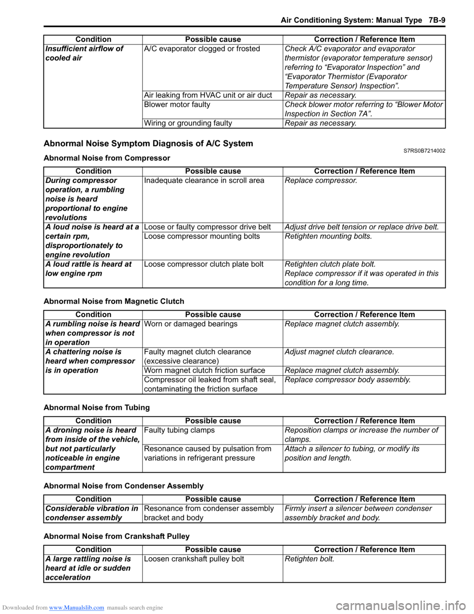
Abnormal Noise Symptom Diagnosis of A/C SystemS7RS0B7214002
Abnormal Noise from Compressor
Abnormal Noise from Magnetic Clutch
Abnormal Noise from Tubing
Abnormal Noise from Condenser Assembly
Abnormal Noise from Crankshaft PulleyInsufficient airflow of
cooled air
A/C evaporator clogged or frosted
Check A/C evaporator and evaporator
thermistor (evaporator temperature sensor)
referring to “Evaporator Inspection” and
“Evaporator Thermistor (Evaporator
Temperature Sensor) Inspection”.
Air leaking from HVAC unit or air duct Repair as necessary.
Blower motor faulty Check blower motor referring to “Blower Motor
Inspection in Section 7A”.
Wiring or grounding faulty Repair as necessary.
Condition Possible cause Correction / Reference Item
Condition
Possible cause Correction / Reference Item
During compressor
operation, a rumbling
noise is heard
proportional to engine
revolutions Inadequate clearance in scroll area
Replace compressor.
A loud noise is heard at a
certain rpm,
disproportionately to
engine revolution Loose or faulty compressor drive belt
Adjust drive belt tension or replace drive belt.
Loose compressor mounting bolts Retighten mounting bolts.
A loud rattle is heard at
low engine rpm Loose compressor clutch plate bolt
Retighten clutch plate bolt.
Replace compressor if it was operated in this
condition for a long time.
Condition Possible cause Correction / Reference Item
A rumbling noise is heard
when compressor is not
in operation Worn or damaged bearings
Replace magnet clutch assembly.
A chattering noise is
heard when compressor
is in operation Faulty magnet clutch clearance
(excessive clearance)
Adjust magnet clutch clearance.
Worn magnet clutch friction surface Replace magnet clutch assembly.
Compressor oil leaked from shaft seal,
contaminating the friction surface Replace compressor body assembly.
Condition
Possible cause Correction / Reference Item
A droning noise is heard
from inside of the vehicle,
but not particularly
noticeable in engine
compartment Faulty tubing clamps
Reposition clamps or increase the number of
clamps.
Resonance caused by pulsation from
variations in re frigerant pressure Attach a silencer to tubing, or modify its
position and length.
Condition
Possible cause Correction / Reference Item
Considerable vibration in
condenser assembly Resonance from condenser assembly
bracket and body Firmly insert a silenc
er between condenser
assembly bracket and body.
Condition Possible cause Correction / Reference Item
A large rattling noise is
heard at idle or sudden
acceleration Loosen crankshaft pulley bolt
Retighten bolt.
Page 958 of 1496
Downloaded from www.Manualslib.com manuals search engine 7B-10 Air Conditioning System: Manual Type
Abnormal Noise from Tension Pulley
Abnormal Noise from A/C Evaporator
Abnormal Noise from Blower Motor
A/C System Performance InspectionS7RS0B7214003
1) Confirm that vehicle and environmental conditions are as follows.
• Vehicle is put indoors.
• Ambient temperature is within 25 – 35 °C (77 – 95
° F).
• Relative humidity is within 30 – 70%.
• There is no wind indoors.
• HVAC unit is normal.
• Blower motor is normal.
• There is no air leakage from air ducts.
• Condenser fins are clean.
• Air filter in HVAC unit is not clogged with dirt and
dust.
• Battery voltage is about 12 V.
• Radiator cooling fan operates normally.
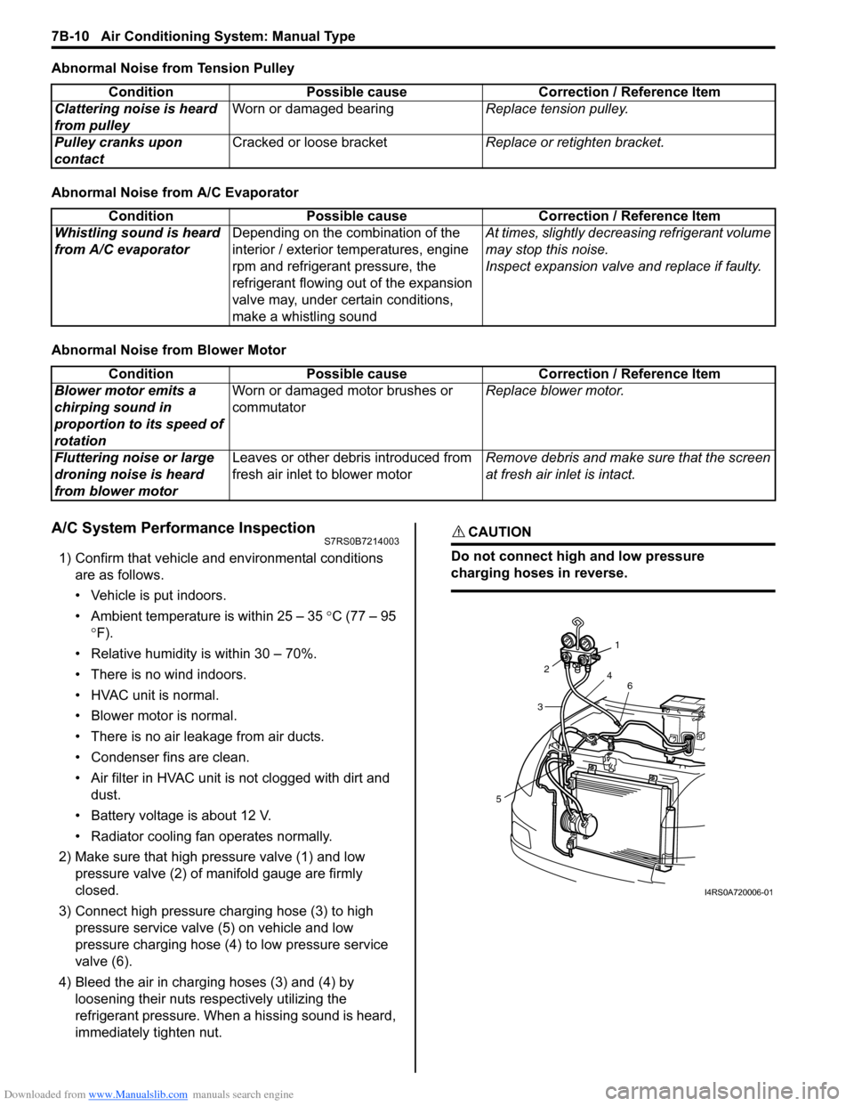
2) Make sure that high pressure valve (1) and low pressure valve (2) of manifold gauge are firmly
closed.
3) Connect high pressure charging hose (3) to high pressure service valve (5) on vehicle and low
pressure charging hose (4) to low pressure service
valve (6).
4) Bleed the air in charging hoses (3) and (4) by loosening their nuts respectively utilizing the
refrigerant pressure. When a hissing sound is heard,
immediately tighten nut.
CAUTION!
Do not connect high and low pressure
charging hoses in reverse.
Condition Possible cause Correction / Reference Item
Clattering noise is heard
from pulley Worn or damaged bearing
Replace tension pulley.
Pulley cranks upon
contact Cracked or loose bracket
Replace or retighten bracket.
ConditionPossible cause Correction / Reference Item
Whistling sound is heard
from A/C evaporator Depending on the combination of the
interior / exterior temperatures, engine
rpm and refrigerant pressure, the
refrigerant flowing out of the expansion
valve may, under certain conditions,
make a whistling sound At times, slightly decrea
sing refrigerant volume
may stop this noise.
Inspect expansion valve and replace if faulty.
Condition Possible cause Correction / Reference Item
Blower motor emits a
chirping sound in
proportion to its speed of
rotation Worn or damaged motor brushes or
commutator
Replace blower motor.
Fluttering noise or large
droning noise is heard
from blower motor Leaves or other debris introduced from
fresh air inlet to blower motor
Remove debris and make sure that the screen
at fresh air inlet is intact.
53
2
1
4 6
I4RS0A720006-01
Page 959 of 1496
Downloaded from www.Manualslib.com manuals search engine Air Conditioning System: Manual Type 7B-11
5) Warm up engine to the normal operating temperature and keep it at the specified idle speed.
6) Turn A/C switch ON, set blower speed selector at maximum speed position, temperature selector at
maximum cold position, airflow selector at face
position, and air intake switch at recirculation
position. (Confirm that A/C compressor and
condenser fans are working.)
7) Wait for ten minutes to stabilize the A/C operation.
8) Open front windows, front doors and engine hood.
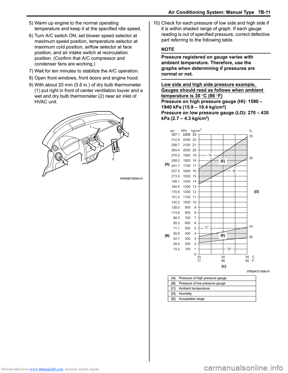
9) With about 20 mm (0.8 in.) of dry bulb thermometer
(1) put right in front of center ventilation louver and a
wet and dry bulb thermometer (2) near air inlet of
HVAC unit. 10) Check for each pressure of low side and high side if
it is within shaded range of graph. If each gauge
reading is out of specified pressure, correct defective
part referring to the following table.
NOTE
Pressure registered on gauge varies with
ambient temperature. Therefore, use the
graphs when determining if pressures are
normal or not.
Low side and high side pressure example,
Gauges should read as follows when ambient
temperature is 30 °C (86 °F)
Pressure on high pressure gauge (HI): 1590 –
1940 kPa (15.9 – 19.4 kg/cm2)
Pressure on low pressure gauge (LO): 270 – 430
kPa (2.7 – 4.3 kg/cm
2)
2
1
I4RS0B720004-01
[A]: Pressure of high pressure gauge
[B]: Pressure of low pressure gauge
[C]: Ambient temperature
[D]: Humidity [E]: Acceptable range
22
312.9 2200
0 1
2 3 30 70 30 70 %
4 5 6 7 8 9
10
11 12 13 14 15
16 17
18
19 21
298.7 2100
20
14.2 28.4 42.7 56.9 71.1 85.3 99.5
113.8 128.0 142.2
151.4
170.6
184.9 199.1
213.3 227.5
241.7
256.0
270.2
284.4
100 200 300 400 500 600 700 800 900
1000 1100 1200
1300
1400 1500 1600
1700 1800
1900
2000
25 30 35
77 86 95
psi kPa kg/cm
2
C
F
“A”
“B”
“C”
“D”
23
2300
327.1
[A]
[B]
[C][D][E]
[E]
I7RS0A721006-01
Page 963 of 1496
Downloaded from www.Manualslib.com manuals search engine Air Conditioning System: Manual Type 7B-15
A/C System Inspection at ECMS7RS0B7214004
Voltage Check
When checking voltage at ECM connector terminals related to A/C system, refer to “DTC P2101: Throttle Actuator
Control Motor Circuit Range / Performance in Section 1A”.
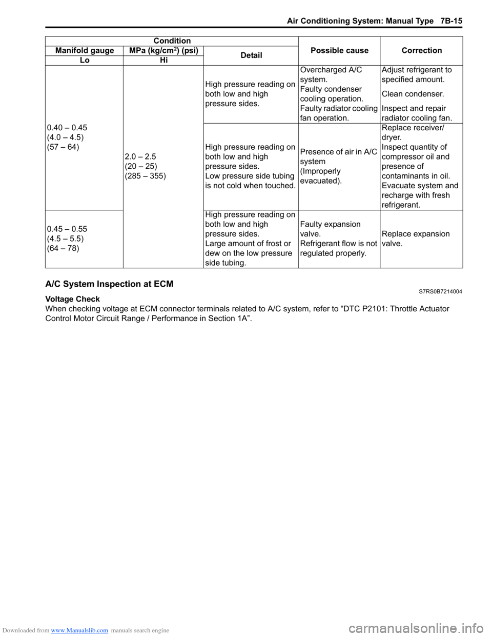
0.40 – 0.45
(4.0 – 4.5)
(57 – 64)
2.0 – 2.5
(20 – 25)
(285 – 355) High pressure reading on
both low and high
pressure sides.
Overcharged A/C
system.
Adjust refrigerant to
specified amount.
Faulty condenser
cooling operation. Clean condenser.
Faulty radiator cooling
fan operation. Inspect and repair
radiator cooling fan.
High pressure reading on
both low and high
pressure sides.
Low pressure side tubing
is not cold when touched. Presence of air in A/C
system
(Improperly
evacuated).Replace receiver/
dryer.
Inspect quantity of
compressor oil and
presence of
contaminants in oil.
Evacuate system and
recharge with fresh
refrigerant.
0.45 – 0.55
(4.5 – 5.5)
(64 – 78) High pressure reading on
both low and high
pressure sides.
Large amount of frost or
dew on the low pressure
side tubing.Faulty expansion
valve.
Refrigerant flow is not
regulated properly.
Replace expansion
valve.
Condition
Possible cause Correction
Manifold gauge MPa (kg/cm
2) (psi)
Detail
Lo Hi
Page 1276 of 1496
Downloaded from www.Manualslib.com manuals search engine 9A-105 Wiring Systems:
E18E19E20E21 E22
IF EQPD
E23 E24 (TO C36) E25E26
RHD
E26 E27E27E28 E29E30
LHD RHD LHD
E31 E32E33E34 E35E36
E37 (TO G35) E38 (TO G36) E39E40
E41 E42E43
E44 (TO L03) E45 (TO L02) E46E47
E48 (TO E50) E49 E50 (TO E48) E51E52
21
MCONF020198-01
12
MCONF020156-01
21
MCONF020197-01
12
3
MCONF030101-01
1
2
MCONF020013-01
123456
202116171819
78910
22232425
12
2726
13
28
313233343536
505146474849
37383940
52535455
11
41
56
42
57
43
58
1415
2930
44
60
45
59
MCONF600003-01
34
7
2
68910
121314
1716
1
5
11
15181920
MCONM200005-01
21
MCONM020043-01
21
MCONF020114-01
1
2
MCONF020170-01
21
MCONF020201-01
1
2
MCONF020169-01
1
2
345
MCONF050015-01
1
2
345
MCONF050015-01
1
2
345
MCONF050015-01
1
2
34
MCONF040004-01
1
2
34
MCONF040004-01
1
2
34
MCONF040004-01
1
2
34
MCONF040004-01
1
2
34
MCONF040004-01
1
2
34
MCONF040004-01
381371251015
14914
2611
MCONM150001-01
54 32 167910
20 19 18 17 16 15 14 13 12 118
MCONM200008-01
1 234
5 678 910
MCONF100003-01
21
MCONF020202-01
6
5
4
3
2
17
11
10
9
8 15
14
13
12 16
MCONF160034-01
CC
AABB
DE
DD
EE
MCONF120059-01
CC
AABB
DE
DD
EE
MCONF120059-01
12
34
MCONF040095-0110 1
6111415 16 171213
2
734
85
9
MCONF170009-01
12567
8
9 1011121314
34
MCONF140012-01
12
34
MCONF040009-01
21
7654
3
8
MCONM080012-01
1
2
MCONF020203-01
2
51
47 6
8
3
MCONF080014-01
1
2
MCONF020204-01
10
11 12 13 14 15 16 17 18 19 123456789
20
MCONF200021-01
Page 1277 of 1496
Downloaded from www.Manualslib.com manuals search engine Wiring Systems: 9A-106
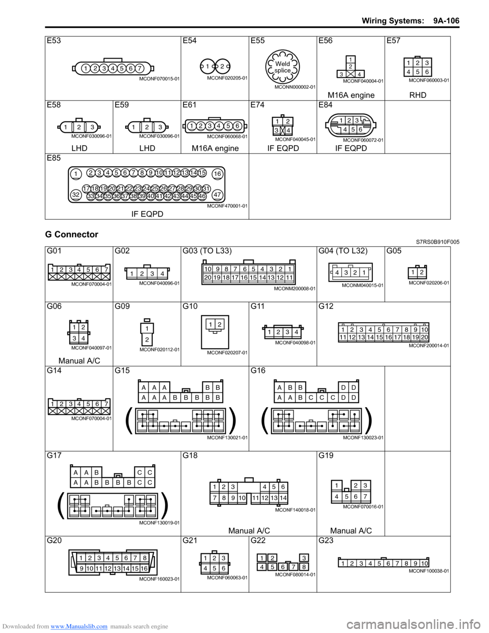
G ConnectorS7RS0B910F005
E53E54E55 E56E57
M16A engine RHD
E58 E59E61E74 E84
LHD LHD M16A engine IF EQPD IF EQPD
E85
IF EQPD
G01 G02G03 (TO L33) G04 (TO L32) G05
G06 G09G10G11G12
Manual A/C
G14 G15 G16
G17 G18G19
Manual A/C Manual A/C
G20 G21G22G23
1234567
MCONF070015-01
12
MCONF020205-01
Weld
splice
MCONN000002-01
1
2
34
MCONF040004-01
123
46 5
MCONF060003-01
1 23
MCONF030096-01
123
MCONF030096-01
1234 56
MCONF060068-01
1
34
2
MCONF040045-01
2
5
46
13
MCONF060072-01
21
3247
163451213141567891011
3334353643444546373839404142181719202128293031222324252627
MCONF470001-01
1234567
MCONF070004-01
1234
MCONF040096-01
54 32 167910
20 19 18 17 16 15 14 13 12 118
MCONM200008-01
12
34
MCONM040015-01
12
MCONF020206-01
12
34
MCONF040097-01
1
2
MCONF020112-01
21
MCONF020207-01
1234
MCONF040098-01
125678911 12 13 14 15 16 17 18 1910
2034
MCONF200014-01
1234567
MCONF070004-01
AAA BB
AAA B
BB
BB
( )
MCONF130021-01
ABB DD
AAB D
CC
CD
( )
MCONF130023-01
AAB CC
AAB C
BB
BC
( )
MCONF130019-01
123
78910
456
11121314
MCONF140018-01
3
7654
21
MCONF070016-01
1234567 8
9 10111213141516
MCONF160023-01
3
21
654
MCONF060063-01
2
51
47 6
8
3
MCONF080014-01
12345678910MCONF100038-01
Page 1278 of 1496
Downloaded from www.Manualslib.com manuals search engine 9A-107 Wiring Systems:
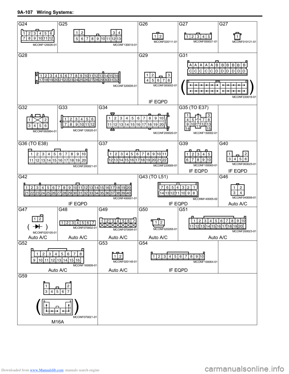
G24G25 G26G27 G27
G28 G29G31
IF EQPD
G32 G33G34 G35 (TO E37)
G36 (TO E38) G37G39G40
IF EQPD IF EQPD
G42 G43 (TO L51)G46
IF EQPD IF EQPDAuto A/C
G47 G48G49G50G51
Auto A/C Auto A/C Auto A/C Auto A/C Auto A/C
G52 G53G54
Auto A/C Auto A/CIF EQPD
G59
M16A
21
83
9 4
10 5
11 6
12
7
MCONF120026-01
710
56 12 34
8 9 11 12 13
MCONF130010-01
21
MCONF020111-01
12345MCONF050021-011
MCONF010121-01
1
17 2
18 3
19 4
20 5
21 6
22 7
23 8
24 9
25 10
26 11
27 12
28 13
29 14
30 15
31 16
32
MCONF320005-01
12 3
8
467 5
MCONF080002-01
AA A A A
BBBB
BB
CCC C CD DD D DD
()
MCONF220018-01
6543 21
MCONF060064-01
12345
78 11 6
12
910
MCONF120028-01
10
11 12 13 14 15 16 17 18 19 123456789
20
MCONF200020-01
14951071214
381315
2611
MCONF150002-01
10
11 12 13 14 15 16 17 18 19 123456789
20
MCONF200021-01
1234567891011
12 13 14 15 16 17 18 19 20 21 22
MCONF220009-01
54321
109876
MCONF100060-01
12
3456
MCONF060025-01
123456
212223242526
7
27
8
28
9
29
10
30
11
31
12
32
13
33
14
34
15
35
16
36
17
37
18
38
19
39
20
40
MCONF400001-01
7 654 3
21
14 13 12 11 10 9 8
MCONM140005-02
12
34
MCONF040009-01
1 2
( )MCONF020105-01
2
14 3657MCONF070002-01
1234567
MCONF070004-01
12
MCONF020268-01
12349105678
11121718192013141516MCONF200023-01
12345678
910151611121314
MCONF160009-01
21
MCONF020148-01
12345678910
MCONF100064-01
12
34567
()
MCONF070021-01