Valve body assembly SUZUKI SWIFT 2007 2.G Service Repair Manual
[x] Cancel search | Manufacturer: SUZUKI, Model Year: 2007, Model line: SWIFT, Model: SUZUKI SWIFT 2007 2.GPages: 1496, PDF Size: 34.44 MB
Page 755 of 1496

Downloaded from www.Manualslib.com manuals search engine Automatic Transmission/Transaxle: 5A-111
8) Remove fluid cooler pipes (1) and pipe union (2).
9) Remove fluid level gauge (3) and fluid filler tube (4).
10) Remove oil pan (1) and oil pan gasket (2).
NOTE
• For removal of oil pan, do not turn transaxle over as this will contaminate
valve body with foreign materials in
bottom of oil pan.
• When removing oil pan, tap around it lightly with plastic ha mmer. Do not force it
off by using screwdriver or the like.
11) Remove oil strain er assembly (1). 12) Disconnect connectors (2) from solenoid valves and
transmission fluid temperature sensor (1).
13) Remove valve body assembly bolts.
CAUTION!
Be careful not to let manual valve fall off
when removing valve body assembly.
NOTE
There are five kinds of bolts (bolts A (1), B (2),
C (3), D (4) and E (5)) fixing valve body
assembly.
14) Remove manual valve rod (1) from manual valve lever (2), then remove valve body assembly (3).
1 2
4
3
I3RM0B510059-01
I2RH0B510086-01
I2RH0B510087-01
1 2I4RS0A510027-01
I2RH0B510089-01
I2RH0B510090-01
Page 783 of 1496
Downloaded from www.Manualslib.com manuals search engine Automatic Transmission/Transaxle: 5A-139
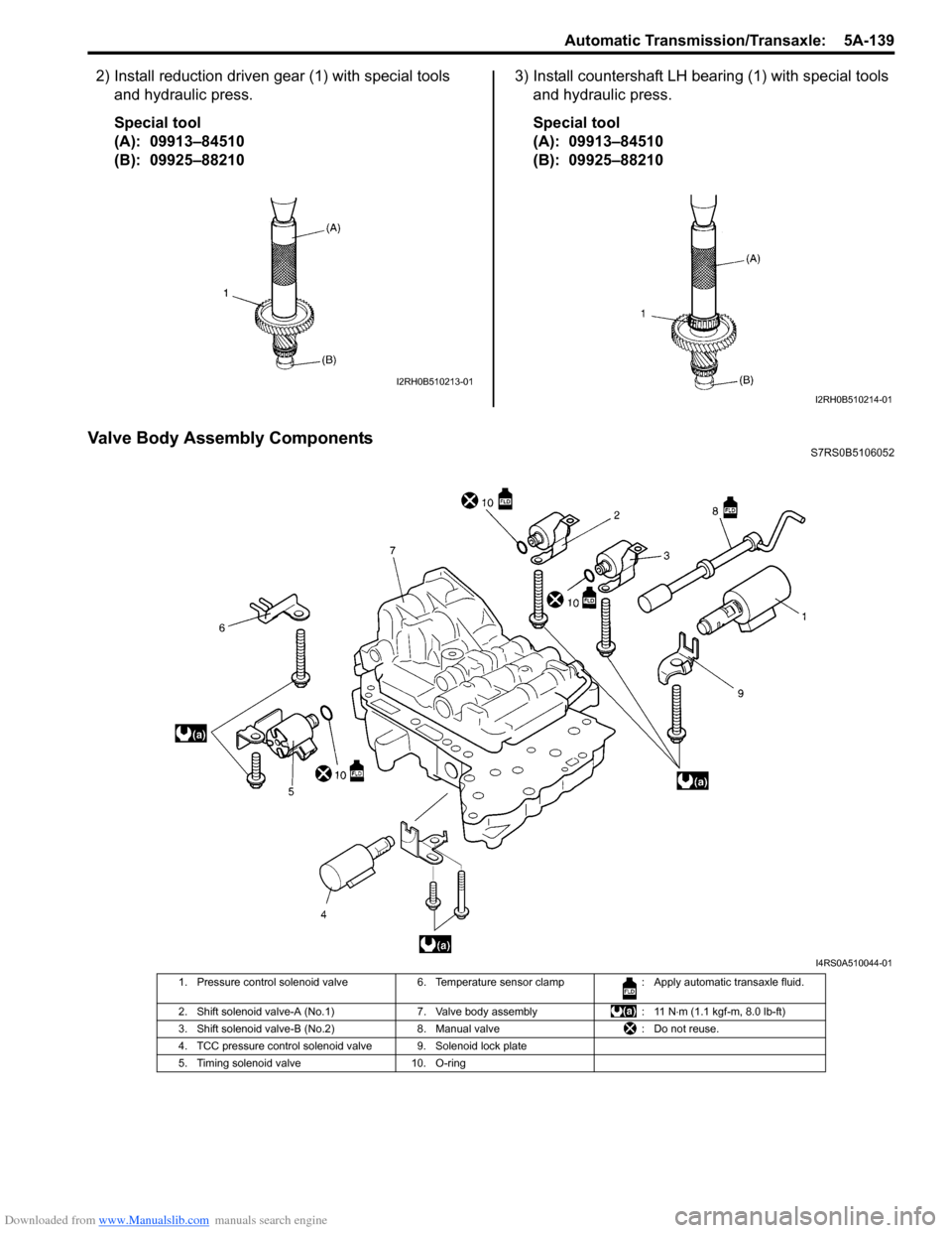
2) Install reduction driven gear (1) with special tools and hydraulic press.
Special tool
(A): 09913–84510
(B): 09925–88210 3) Install countershaft LH bearing (1) with special tools
and hydraulic press.
Special tool
(A): 09913–84510
(B): 09925–88210
Valve Body Assembly ComponentsS7RS0B5106052
I2RH0B510213-01
I2RH0B510214-01
I4RS0A510044-01
1. Pressure control solenoid valve 6. Temperature sensor clamp : Apply automatic transaxle fluid.
2. Shift solenoid valve-A (No.1) 7. Valve body assembly: 11 N⋅m (1.1 kgf-m, 8.0 lb-ft)
3. Shift solenoid valve-B (No.2) 8. Manual valve: Do not reuse.
4. TCC pressure control solenoid valve 9. Solenoid lock plate
5. Timing solenoid valve 10. O-ring
Page 784 of 1496
Downloaded from www.Manualslib.com manuals search engine 5A-140 Automatic Transmission/Transaxle:
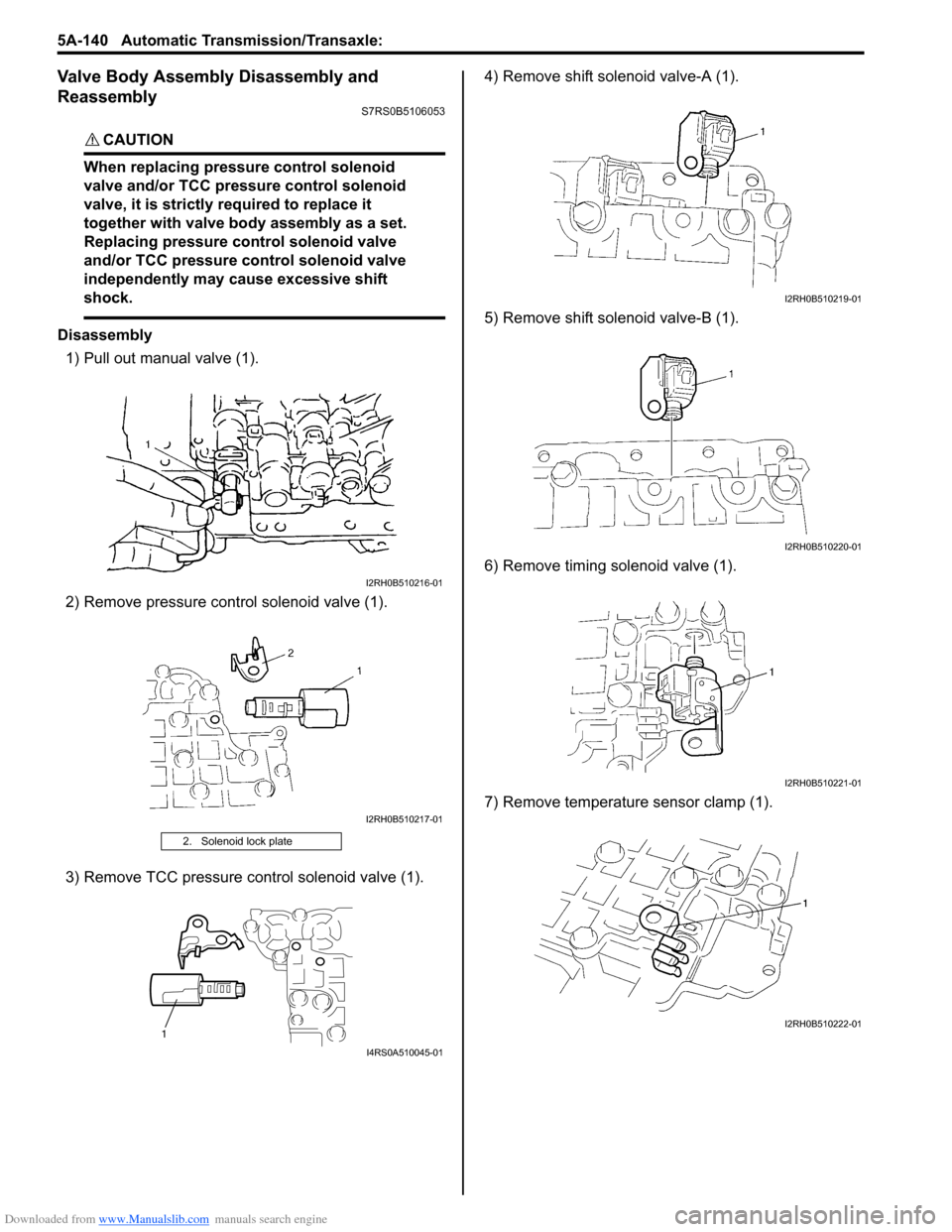
Valve Body Assembly Disassembly and
Reassembly
S7RS0B5106053
CAUTION!
When replacing pressure control solenoid
valve and/or TCC pressure control solenoid
valve, it is strictly required to replace it
together with valve body assembly as a set.
Replacing pressure control solenoid valve
and/or TCC pressure control solenoid valve
independently may cause excessive shift
shock.
Disassembly1) Pull out manual valve (1).
2) Remove pressure cont rol solenoid valve (1).
3) Remove TCC pressure control solenoid valve (1). 4) Remove shift solenoid valve-A (1).
5) Remove shift solenoid valve-B (1).
6) Remove timing solenoid valve (1).
7) Remove temperature sensor clamp (1).
2. Solenoid lock plate
I2RH0B510216-01
I2RH0B510217-01
1
I4RS0A510045-01
I2RH0B510219-01
I2RH0B510220-01
I2RH0B510221-01
I2RH0B510222-01
Page 785 of 1496
Downloaded from www.Manualslib.com manuals search engine Automatic Transmission/Transaxle: 5A-141
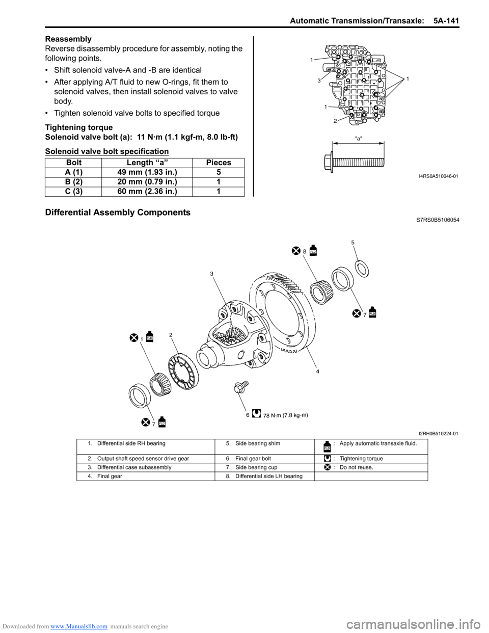
Reassembly
Reverse disassembly procedure for assembly, noting the
following points.
• Shift solenoid valve-A and -B are identical
• After applying A/T fluid to new O-rings, fit them to solenoid valves, then insta ll solenoid valves to valve
body.
• Tighten solenoid valve bolts to specified torque
Tightening torque
Solenoid valve bolt (a): 11 N·m (1.1 kgf-m, 8.0 lb-ft)
Solenoid valve bolt specification
Differential Assembly ComponentsS7RS0B5106054
Bolt Length “a” Pieces
A (1) 49 mm (1.93 in.) 5
B (2) 20 mm (0.79 in.) 1
C (3) 60 mm (2.36 in.) 1
1
1
1
3
2
"a"
I4RS0A510046-01
I2RH0B510224-01
1. Differential side RH bearing 5. Side bearing shim: Apply automatic transaxle fluid.
2. Output shaft speed sensor drive gear 6. Final gear bolt: Tightening torque
3. Differential case subassembly 7. Side bearing cup: Do not reuse.
4. Final gear 8. Differential side LH bearing
Page 807 of 1496
Downloaded from www.Manualslib.com manuals search engine Automatic Transmission/Transaxle: 5A-163
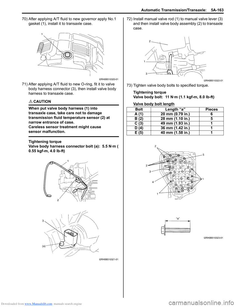
70) After applying A/T fluid to new governor apply No.1 gasket (1), install it to transaxle case.
71) After applying A/T fluid to new O-ring, fit it to valve body harness connector (3), then install valve body
harness to transaxle case.
CAUTION!
When put valve body harness (1) into
transaxle case, take care not to damage
transmission fluid temperature sensor (2) at
narrow entrance of case.
Careless sensor treatment might cause
sensor malfunction.
Tightening torque
Valve body harness connector bolt (a): 5.5 N·m (
0.55 kgf-m, 4.0 lb-ft) 72) Install manual valve rod (1) to manual valve lever (3)
and then install valve body assembly (2) to transaxle
case.
73) Tighten valve body bolts to specified torque. Tightening torque
Valve body bolt: 11 N·m (1.1 kgf-m, 8.0 lb-ft)
Valve body bolt length
I2RH0B510320-01
I2RH0B510321-01
Bolt Length “a” Pieces
A (1) 20 mm (0.79 in.) 6
B (2) 28 mm (1.10 in.) 5
C (3) 49 mm (1.93 in.) 1
D (4) 36 mm (1.42 in.) 1
E (5) 40 mm (1.58 in.) 1
I2RH0B510322-01
I2RH0B510323-01
Page 811 of 1496

Downloaded from www.Manualslib.com manuals search engine Automatic Transmission/Transaxle: 5A-167
Specifications
Tightening Torque SpecificationsS7RS0B5107001
NOTE
The specified tightening torque is also described in the following.
“Select Cable Components”
“Automatic Transaxle Unit Components”
“Automatic Transaxle Assembly Components”
“Oil Pump Assembly Components”
“Transaxle Rear Cover (O/D and 2nd Coast Brake Piston) Assembly Components”
“Valve Body Assembly Components”
“Differential Assembly Components”
Reference:
For the tightening torque of fastener not specified in this section, refer to “Fasteners Information in Section 0A”.
Fastening part
Tightening torque
Note
N ⋅mkgf-mlb-ft
A/T fluid drain plug 171.7 12.5 �) / �) / �)
Transmission range sensor bolt 5.5 0.55 4.0�) / �)
Output shaft speed sensor bolt 131.3 9.5 �) / �)
Input shaft speed sensor bolt 5.5 0.55 4.0�)
Valve body harness connector bolt 7.00.7 5.0 �)
Shift solenoid bolt 111.1 8.0 �)
Oil strainer bolt 101.0 7.5 �) / �)
Oil pan bolt 7.00.7 5.0 �) / �)
Transaxle and engine fastening bolt and nut 85 8.5 61.5�)
Drive plate to torque converter bolt 252.5 18.0 �)
Transaxle stiffener bolt 555.5 40�)
Starter motor bolt and nut 505.0 36.5 �)
Oil pump subassembly bolt 101.0 7.5 �)
Rear cover plug 7.5 0.75 5.5�)
Solenoid valve bolt 111.1 8.0 �)
Final gear bolt 787.8 56.5 �)
Torque converter housing plug 7.5 0.75 5.5�)
Lubrication tube clamp bolt 5.5 0.55 4.0�)
Fluid reservoir RH plate bolt 5.5 0.55 4.0�)
Torque converter housing bolt 292.9 21�) / �) / �)
Manual detent spring bolt 101.0 7.5 �)
Parking lock pawl bracket bolt 7.5 0.75 5.5�)
Rear cover bolt 252.5 18.0 �)
Fluid reservoir LH plate bolt 101.0 7.5 �)
Oil pump assembly bolt 252.5 18.0 �)
Transaxle case plug 7.5 0.75 5.5�)
Valve body harness connector bolt 5.5 0.55 4.0�)
Valve body bolt 111.1 8.0 �)
Fluid outlet union 252.5 18.0 �)
Fluid cooler pipe union bolt 222.2 16.0 �)
Fluid cooler pipe bracket bolt 101.0 7.5 �)
Fluid filler tube bolt 101.0 7.5 �)
Input shaft speed sensor bolt 111.1 8.0 �)
Harness bracket bolt 232.3 17.0 �)
Select cable clamp bolt 101.0 7.5 �)
Transmission range sensor lock nut 70.7 5.0 �)
Manual select lever nut 131.3 9.5 �)
Engine mounting LH bracket bolt 555.5 40.0
�)
Page 812 of 1496
Downloaded from www.Manualslib.com manuals search engine 5A-168 Automatic Transmission/Transaxle:
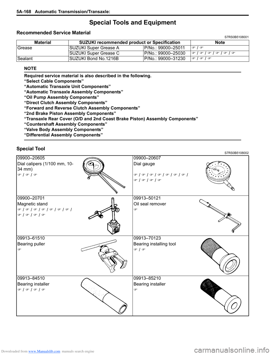
Special Tools and Equipment
Recommended Service MaterialS7RS0B5108001
NOTE
Required service material is also described in the following.
“Select Cable Components”
“Automatic Transaxle Unit Components”
“Automatic Transaxle Assembly Components”
“Oil Pump Assembly Components”
“Direct Clutch Assembly Components”
“Forward and Reverse Clutch Assembly Components”
“2nd Brake Piston Assembly Components”
“Transaxle Rear Cover (O/D and 2nd Coast Brake Piston) Assembly Components”
“Countershaft Assembly Components”
“Valve Body Assembly Components”
“Differential Assembly Components”
Special ToolS7RS0B5108002
Material SUZUKI recommended product or Specification Note
Grease SUZUKI Super Grease A P/No.: 99000–25011�) / �)
SUZUKI Super Grease C P/No.: 99000–25030�) / �) / �) / �) / �) / �)
Sealant SUZUKI Bond No.1216B P/No.: 99000–31230�) / �) / �)
09900–20605 09900–20607
Dial calipers (1/100 mm, 10-
34 mm) Dial gauge
�) / �) / �)�) / �) / �) / �) / �) / �) / �) /
�) / �) / �) / �)
09900–20701 09913–50121
Magnetic stand Oil seal remover
�) / �) / �) / �) / �) / �) / �) /
�) / �) / �) / �) �)
09913–61510 09913–70123
Bearing puller Bearing installing tool
�)�) / �)
09913–84510 09913–85210
Bearing installer Bearing installer
�) / �) / �) / �)�)
Page 972 of 1496

Downloaded from www.Manualslib.com manuals search engine 7B-24 Air Conditioning System: Manual Type
HVAC Unit Removal and InstallationS7RS0B7216006
Removal1) Disconnect negative (–) cable from battery.
2) Disable air bag system referring to “Disabling Air Bag System in Section 8B”.
3) Recover refrigerant from A/C system with recovery and recycling equipment referring to “Recovery” in
“Operation Procedure for Refrigerant Charge”.
4) Remove cowl top panel referring to “Cowl Top Components in Section 9K”.
5) Drain engine coolant, and then disconnect heater hoses (1) from HVAC unit (2).
6) Remove instrument panel from vehicle body referring to “Audio Unit Re moval and Installation in
Section 9C”.
7) Loosen suction hose and liquid pipe bolt (4).
8) Remove nuts (3).
9) Remove HVAC unit from vehicle body. Installation
Reverse removal procedure noting the following
instructions.
• Replenish specified amount of compressor oil to
compressor suction side referring to “Replenishing
Compressor Oil” in “Operation Procedure for
Refrigerant Charge”.
• Install the padding (1) to the installation hole uniformly.
• Evacuate and charge the A/C system referring to “Evacuation” and “Charge” in “Operation Procedure
for Refrigerant Charge”.
• Adjust control cables referr ing to “HVAC Control Unit
Removal and Installati on in Section 7A”.
• Enable air bag system referring to “Enabling Air Bag System in Section 8B”.
Evaporator InspectionS7RS0B7216007
Check the followings.
• Clog of A/C evaporator fins.If any clogs are found, A/C evaporator fins should be
washed with water, and then should be dried with
compressed air.
• A/C evaporator fins for leakage and breakage. If any defects are found, repair or replace A/C
evaporator.
• A/C evaporator fittings for leakage. If any defects are found, repair or replace A/C
evaporator.
2. Blower upper case 8. Temperature control door assembly 14. Temperature control lever 20. Packing
3. Air intake control actuator 9. Blower motor resistor 15. Airflow control lever21. Filter cover (if equipped)
4. HVAC Air filter (if equipped) 10. Blower lower case 16. Evaporator22. Drain hose
5. Heater unit upper case 11. Blower motor 17. O-ring23. Cable lock clamp
6. Foot duct 12. Heater unit lower case 18. Expansion valve: Do not reuse.
3
2
3
3
1
4
I4RS0B720009-01
1
I4RS0B720010-01
Page 979 of 1496
Downloaded from www.Manualslib.com manuals search engine Air Conditioning System: Manual Type 7B-31
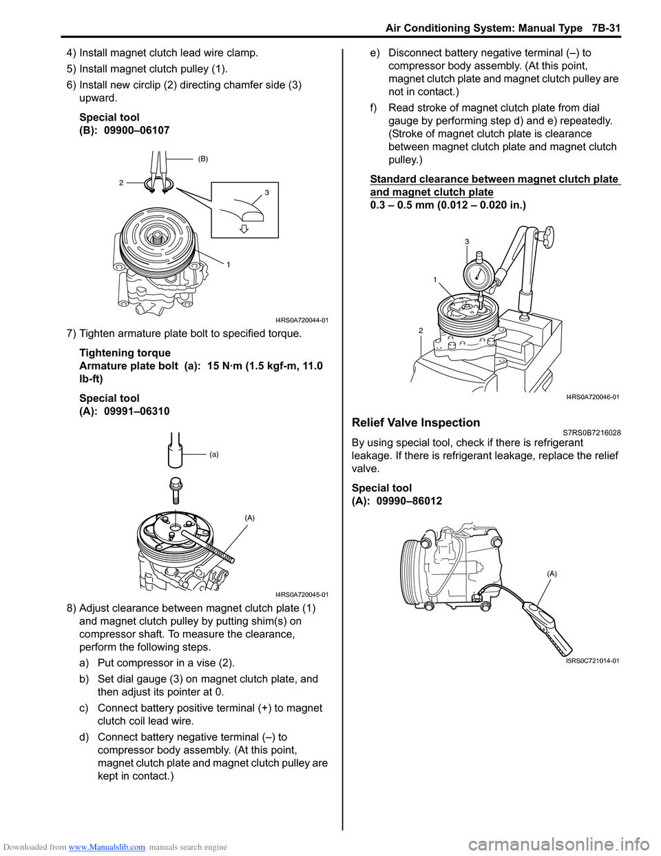
4) Install magnet clutch lead wire clamp.
5) Install magnet clutch pulley (1).
6) Install new circlip (2) directing chamfer side (3) upward.
Special tool
(B): 09900–06107
7) Tighten armature plate bolt to specified torque. Tightening torque
Armature plate bolt (a): 15 N·m (1.5 kgf-m, 11.0
lb-ft)
Special tool
(A): 09991–06310
8) Adjust clearance between magnet clutch plate (1) and magnet clutch pulley by putting shim(s) on
compressor shaft. To measure the clearance,
perform the following steps.
a) Put compressor in a vise (2).
b) Set dial gauge (3) on magnet clutch plate, and then adjust its pointer at 0.
c) Connect battery positive terminal (+) to magnet clutch coil lead wire.
d) Connect battery negative terminal (–) to compressor body assemb ly. (At this point,
magnet clutch plate and magnet clutch pulley are
kept in contact.) e) Disconnect battery negative terminal (–) to
compressor body assembly. (At this point,
magnet clutch plate and magnet clutch pulley are
not in contact.)
f) Read stroke of magnet clutch plate from dial gauge by performing step d) and e) repeatedly.
(Stroke of magnet clutch plate is clearance
between magnet clutch plate and magnet clutch
pulley.)
Standard clearance between magnet clutch plate
and magnet clutch plate
0.3 – 0.5 mm (0.012 – 0.020 in.)
Relief Valve InspectionS7RS0B7216028
By using special tool, chec k if there is refrigerant
leakage. If there is refrigerant leakage, replace the relief
valve.
Special tool
(A): 09990–86012
1
32 (B)
I4RS0A720044-01
(a)
(A)
I4RS0A720045-01
21
3
I4RS0A720046-01
(A)
I5RS0C721014-01