special tools SUZUKI SWIFT 2007 2.G Service Repair Manual
[x] Cancel search | Manufacturer: SUZUKI, Model Year: 2007, Model line: SWIFT, Model: SUZUKI SWIFT 2007 2.GPages: 1496, PDF Size: 34.44 MB
Page 640 of 1496
Downloaded from www.Manualslib.com manuals search engine 4F-66 Electronic Stability Program:
Specifications
Tightening Torque SpecificationsS7RS0B4607001
Reference:
For the tightening torque of fastener not specified in this section, refer to “Fasteners Information in Section 0A”.
NOTE
The specified tightening torque is also described in the following.
“ESP® Hydraulic Unit / Control Module Assembly Removal and Installation”
Special Tools and Equipment
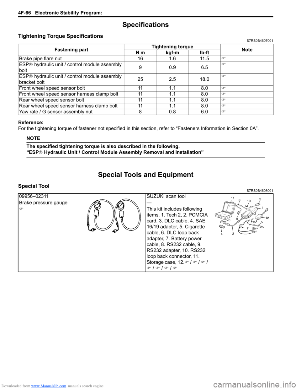
Special ToolS7RS0B4608001
Fastening part Tightening torque
Note
N ⋅mkgf-mlb-ft
Brake pipe flare nut 16 1.6 11.5 �)
ESP ® hydraulic unit / control module assembly
bolt 90.9 6.5�)
ESP ® hydraulic unit / control module assembly
bracket bolt 25 2.5 18.0�)
Front wheel speed sensor bolt 11 1.1 8.0 �)
Front wheel speed sensor harness clamp bolt 11 1.1 8.0 �)
Rear wheel speed sensor bolt 11 1.1 8.0 �)
Rear wheel speed sensor har ness clamp bolt 11 1.1 8.0 �)
Yaw rate / G sensor assembly nut 8 0.8 6.0 �)
09956–02311SUZUKI scan tool
Brake pressure gauge —
�) This kit includes following
items. 1. Tech 2, 2. PCMCIA
card, 3. DLC cable, 4. SAE
16/19 adapter, 5. Cigarette
cable, 6. DLC loop back
adapter, 7. Battery power
cable, 8. RS232 cable, 9.
RS232 adapter, 10. RS232
loop back connector, 11.
Storage case, 12.�) / �) / �) /
�) / �) / �) / �)
Page 642 of 1496

Downloaded from www.Manualslib.com manuals search engine 5-ii Table of Contents
DTC P1878: Torque Converter Clutch Shudder .......................................................... 5A-75
DTC P2762: Torque Converter Clutch (TCC) Pressure Control Sole noid Control Circuit
Range /Performance ....................................... 5A-76
DTC P2763: Torque Converter Clutch Pressure Control Sole noid Control Circuit
High ................................................................. 5A-78
DTC P2764: Torque Converter Clutch Circuit Pressure Control Sole noid Control Circuit
Low ................................................................. 5A-80
Inspection of TCM and Its Circuits .................... 5A-82
TCM Power and Ground Circuit Check ............. 5A-86
Brake Interlock System Inspection .................... 5A-87
Repair Instructions ........... .................................5A-88
Learning Control Initializat ion ............................ 5A-88
A/T Fluid Level Check ....................................... 5A-89
A/T Fluid Change .............................................. 5A-90
Select Lever Components ... .............................. 5A-90
Select Lever Assembly Removal and Installation ....................................................... 5A-90
Select Lever Knob Installa tion........................... 5A-90
Select Lever Inspection .... ................................. 5A-91
“3” Position Switch Inspec tion ........................... 5A-91
Shift Lock Solenoid Inspec tion .......................... 5A-91
Shift Lock Solenoid Replacement ..................... 5A-91
Select Cable Components ................................ 5A-92
Select Cable Removal and Installation ............. 5A-92
Select Cable Adjustment ................................... 5A-93
Key Interlock Cable Removal and Installation... 5A-93
Transmission Range Sensor (Shift Switch) Inspection and Adjustment .............................. 5A-95
Output Shaft Speed Sensor Removal and Installation ....................................................... 5A-96
Output Shaft Speed Sensor Inspection ............. 5A-96
Input Shaft Speed Sensor Removal and Installation ....................................................... 5A-96
Input Shaft Speed Sensor Inspection................ 5A-97
Transmission Fluid Temperature Sensor Removal and Installation ................................. 5A-97
Transmission Fluid Temperature Sensor Inspection ........................................................ 5A-98
Solenoid Valves (Shift Solenoid Valves and Timing Solenoid Valve) Removal and
Installation ....................................................... 5A-98
Solenoid Valves (Shift Solenoid Valves, and Timing Solenoid Valve) Inspection .................. 5A-99
Pressure Control Soleno id Valves (Pressure
Control Solenoid and TCC Pressure Control
Solenoid) Removal and Inst allation .............. 5A-101
Pressure Control Solenoid Valve Inspection ... 5A-101
Transmission Control Module (TCM) Removal and Installation ............................... 5A-102
A/T Relay Inspection ....................................... 5A-103
Differential Side Oil Seal Replacement ........... 5A-103
A/T Fluid Cooler Hoses Replacement ............. 5A-104
Automatic Transaxle Unit Components........... 5A-105
Automatic Transaxle Unit Dismounting and Remounting ................................................... 5A-106
Automatic Transaxle Asse mbly Components . 5A-108 Automatic Transaxle Unit
Disassembly........... 5A-110
Oil Pump Assembly Components ................... 5A-121
Oil Pump Assembly Disassembly and Reassembly .................................................. 5A-122
Oil Pump Assembly Inspection ....................... 5A-122
Direct Clutch Assembly Components.............. 5A-124
Direct Clutch Assembly Preliminary Check ..... 5A-124
Direct Clutch Assembly Disassembly and Reassembly .................................................. 5A-125
Direct Clutch Assembly Inspection.................. 5A-127
Forward and Reverse Clutch Assembly Components .................................................. 5A-128
Forward and Reverse Clutch Assembly Preliminary Check ......................................... 5A-129
Forward and Reverse Clutch Assembly Disassembly and Reassembly ...................... 5A-129
Forward and Reverse Clutch Assembly Inspection ...................................................... 5A-133
2nd Brake Piston Assembly Components ....... 5A-134
2nd Brake Piston Assembly Disassembly and Reassembly .................................................. 5A-134
Transaxle Rear Cover (O/D and 2nd Coast Brake Piston) Assembly Components........... 5A-135
Transaxle Rear Cover (O/D and 2nd Coast Brake Piston) Assembly Disassembly and
Reassembly .................................................. 5A-136
Transaxle Rear Cover (O/D and 2nd Coast Brake Piston) Assembly Inspection............... 5A-137
Countershaft Assembly Co mponents.............. 5A-138
Countershaft Assembly Disassembly and Reassembly .................................................. 5A-138
Valve Body Assembly Components ................ 5A-139
Valve Body Assembly Disassembly and Reassembly .................................................. 5A-140
Differential Assembly Components ................. 5A-141
Differential Assembly Disassembly and Reassembly .................................................. 5A-142
Differential Assembly Inspection ..................... 5A-143
Torque Converter Housing Disassembly and Reassembly .................................................. 5A-144
Transaxle Case Disassembly and Reassembly .................................................. 5A-146
Automatic Transaxle Unit Inspection and Adjus
tment .................................................... 5A-147
Automatic Transaxle Unit Assembly ............... 5A-150
Specifications .................. .................................5A-167
Tightening Torque Specifications .................... 5A-167
Special Tools and Equipmen t .........................5A-168
Recommended Service Material ..................... 5A-168
Special Tool .................................................... 5A-168
Manual Transmission/Tr ansaxle ............ 5B-1
General Description .............................................5B-1
Manual Transaxle Construction and Servicing .... 5B-1
Diagnostic Information and Procedures ............5B-3 Manual Transaxle Symptom Diagnosis............... 5B-3
Repair Instructions ............ ..................................5B-3
Manual Transaxle Oil Change............................. 5B-3
Differential Side Oil Seal Replacement ............... 5B-4
Page 643 of 1496
Downloaded from www.Manualslib.com manuals search engine Table of Contents 5-iii
Gear Shift Control Lever and Cable Components...................................................... 5B-5
Gear Shift Control Le ver and Cable Removal
and Installation .................................................. 5B-6
Gear Select Control Cable Adjustment ............... 5B-6
Back Up Light Switch Removal and Installation ......................................................... 5B-7
Back Up Light Switch Inspection ......................... 5B-7
Manual Transaxle Unit Components ................... 5B-8
Manual Transaxle Unit Dismounting and Remounting....................................................... 5B-9
Gear Shift and Sele ct Shaft Assembly
Components.................................................... 5B-11
Gear Shift and Sele ct Shaft Assembly
Removal and Installation................................. 5B-11
Gear Shift and Select Shaft Disassembly and Assembly ........................................................ 5B-12
Manual Transaxle Assembly Components........ 5B-13
Fifth Gear Disassembly and Assembly ............. 5B-14
Manual Transaxle Assembly Disassembly and Reassembly ............................................. 5B-16
Transaxle Right Case Disassembly and Assembly ........................................................ 5B-23
Transaxle Left Case Disassembly and Assembly ........................................................ 5B-24
Input Shaft and Countershaft Components....... 5B-25
Input Shaft Assembly Disassembly and Reassembly .................................................... 5B-26
Countershaft Assembly Disassembly and Reassembly .................................................... 5B-28
Synchronizer Parts Inspec tion .......................... 5B-31
Gear Shift Shaft Components ........................... 5B-31
5th and Reverse Gear Shift Shafts Disassembly and Assembly ............................ 5B-32
Gear Shift Shaft and Fork Inspection ................ 5B-32
Differential Components ................................... 5B-33
Differential Disassembly and Assembly ............ 5B-33
Specifications ..................................................... 5B-35
Tightening Torque Specifications ...................... 5B-35
Special Tools and Equipmen t ........................... 5B-36
Recommended Service Material ....................... 5B-36 Special Tool ...................................................... 5B-36
Clutch ................
.............................. ......... 5C-1
General Description .............................................5C-1
Clutch Construction .............................................5C-1
Diagnostic Information and Procedures ............5C-2 Clutch System Symptom Diagnosis ....................5C-2
Repair Instructions ........... ...................................5C-2
Clutch Pedal Inspection ......................................5C-2
Clutch Fluid Level Inspection ..............................5C-3
Air Bleeding of Clutch System.............................5C-3
Clutch Pedal Position (CPP) Switch Removal and Installation ..................................................5C-4
Clutch Pedal Position (CPP) Switch Inspection and Adjustment ................................5C-5
Clutch Fluid Pipe and Hose Components ...........5C-5
Clutch Fluid Pipe Removal and Installation.........5C-6
Clutch Fluid Pipe Inspection................................5C-6
Clutch Master Cylinder Removal and Installation .........................................................5C-6
Clutch Operating Cylinder Removal and Installation .........................................................5C-7
Clutch Operating Cylinder Inspection..................5C-7
Clutch Pedal and Clutch Pedal Bracket Components ......................................................5C-7
Clutch Cover, Clutch Disc and Flywheel Components ......................................................5C-8
Clutch Cover, Clutch Disc and Flywheel Removal and Installation ...................................5C-8
Clutch Cover, Clutch Disc and Flywheel Inspection ........................................................5C-10
Clutch Release Syst em Removal and
Installation .......................................................5C-11
Clutch Release System Inspection ...................5C-13
Specifications .................... .................................5C-13
Tightening Torque Specifications ......................5C-13
Special Tools and Equipmen t ...........................5C-14
Recommended Service Material .......................5C-14
Special Tool ......................................................5C-14
Page 754 of 1496
Downloaded from www.Manualslib.com manuals search engine 5A-110 Automatic Transmission/Transaxle:
Automatic Transaxle Unit DisassemblyS7RS0B5106033
CAUTION!
• Thoroughly clean transaxle exterior before overhauling it.
• Keep working table, tools and hands clean while overhauling.
• Use special care to handle aluminum parts so as not to damage them.
• Do not expose removed parts to dust. Keep them always clean.
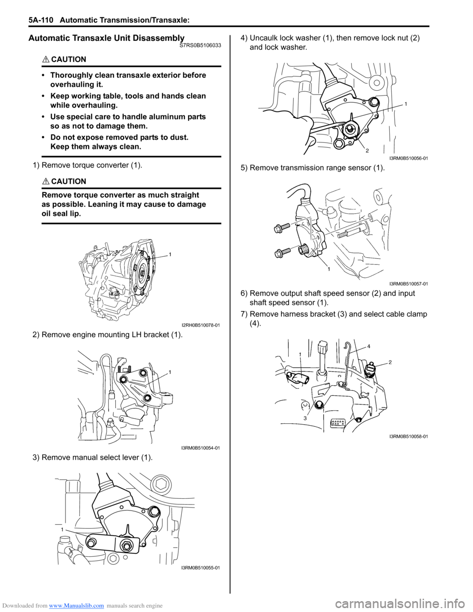
1) Remove torque converter (1).
CAUTION!
Remove torque converte r as much straight
as possible. Leaning it may cause to damage
oil seal lip.
2) Remove engine mounting LH bracket (1).
3) Remove manual select lever (1). 4) Uncaulk lock washer (1),
then remove lock nut (2)
and lock washer.
5) Remove transmission range sensor (1).
6) Remove output shaft speed sensor (2) and input shaft speed sensor (1).
7) Remove harness bracket (3) and select cable clamp (4).
I2RH0B510078-01
I3RM0B510054-01
1
I3RM0B510055-01
1
2
I3RM0B510056-01
I3RM0B510057-01
I3RM0B510058-01
Page 763 of 1496
Downloaded from www.Manualslib.com manuals search engine Automatic Transmission/Transaxle: 5A-119
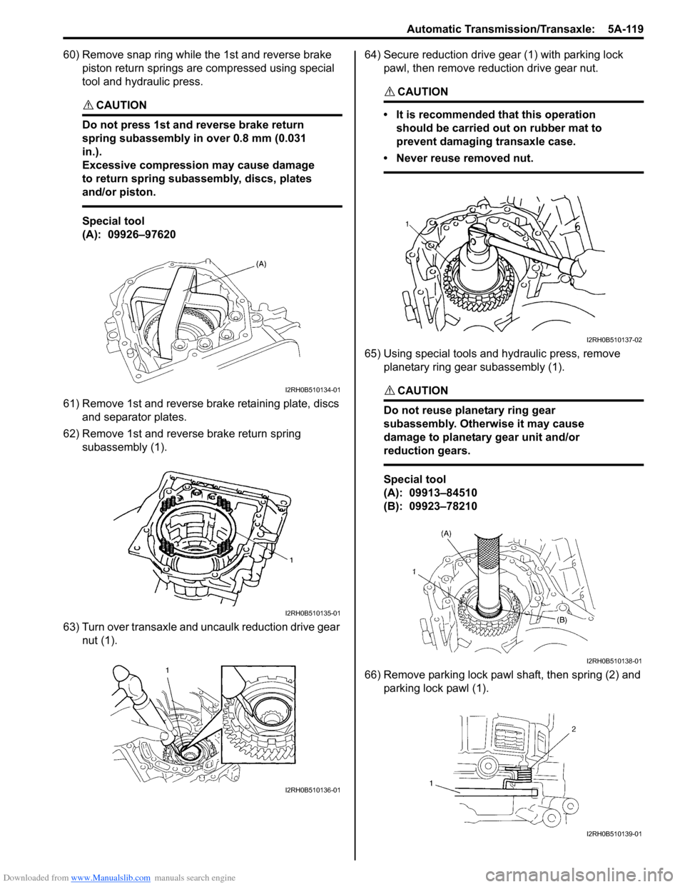
60) Remove snap ring while the 1st and reverse brake piston return springs are compressed using special
tool and hydraulic press.
CAUTION!
Do not press 1st and reverse brake return
spring subassembly in over 0.8 mm (0.031
in.).
Excessive compression may cause damage
to return spring subassembly, discs, plates
and/or piston.
Special tool
(A): 09926–97620
61) Remove 1st and reverse brake retaining plate, discs and separator plates.
62) Remove 1st and reverse brake return spring subassembly (1).
63) Turn over transaxle and uncaulk reduction drive gear nut (1). 64) Secure reduction drive gear (1) with parking lock
pawl, then remove reduction drive gear nut.
CAUTION!
• It is recommended that this operation should be carried out on rubber mat to
prevent damaging transaxle case.
• Never reuse removed nut.
65) Using special tools and hydraulic press, remove planetary ring gear subassembly (1).
CAUTION!
Do not reuse planetary ring gear
subassembly. Otherwise it may cause
damage to planetary gear unit and/or
reduction gears.
Special tool
(A): 09913–84510
(B): 09923–78210
66) Remove parking lock pawl shaft, then spring (2) and parking lock pawl (1).
I2RH0B510134-01
I2RH0B510135-01
I2RH0B510136-01
I2RH0B510137-02
I2RH0B510138-01
I2RH0B510139-01
Page 780 of 1496
Downloaded from www.Manualslib.com manuals search engine 5A-136 Automatic Transmission/Transaxle:
Transaxle Rear Cover (O/D and 2nd Coast Brake
Piston) Assembly Disassembly and
Reassembly
S7RS0B5106048
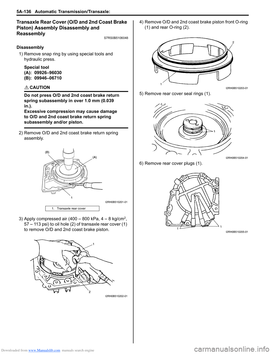
Disassembly1) Remove snap ring by using special tools and hydraulic press.
Special tool
(A): 09926–96030
(B): 09946–06710
CAUTION!
Do not press O/D and 2nd coast brake return
spring subassembly in over 1.0 mm (0.039
in.).
Excessive compression may cause damage
to O/D and 2nd coast brake return spring
subassembly and/or piston.
2) Remove O/D and 2nd coast brake return spring assembly.
3) Apply compressed air (400 – 800 kPa, 4 – 8 kg/cm
2,
57 – 113 psi) to oil hole (2) of transaxle rear cover (1)
to remove O/D and 2nd coast brake piston. 4) Remove O/D and 2nd coast brake piston front O-ring
(1) and rear O-ring (2).
5) Remove rear cove r seal rings (1).
6) Remove rear cover plugs (1).
1. Transaxle rear cover
I2RH0B510201-01
I2RH0B510202-01
I2RH0B510203-01
I2RH0B510204-01
I2RH0B510205-01
Page 782 of 1496
Downloaded from www.Manualslib.com manuals search engine 5A-138 Automatic Transmission/Transaxle:
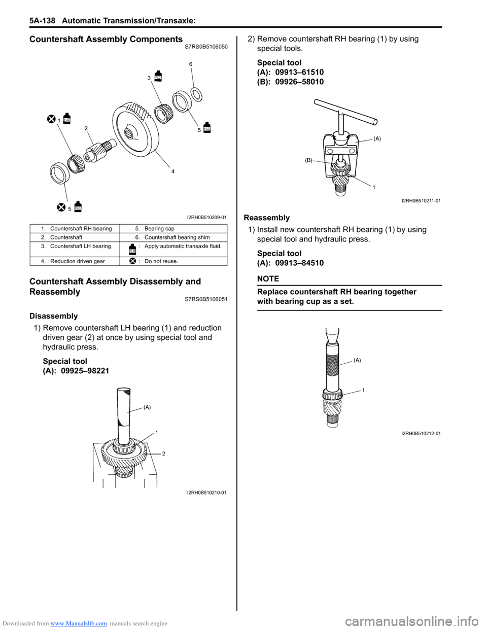
Countershaft Assembly ComponentsS7RS0B5106050
Countershaft Assembly Disassembly and
Reassembly
S7RS0B5106051
Disassembly1) Remove countershaft LH bearing (1) and reduction driven gear (2) at once by using special tool and
hydraulic press.
Special tool
(A): 09925–98221 2) Remove countershaft RH bearing (1) by using
special tools.
Special tool
(A): 09913–61510
(B): 09926–58010
Reassembly 1) Install new countershaft RH bearing (1) by using special tool and hydraulic press.
Special tool
(A): 09913–84510
NOTE
Replace countershaft RH bearing together
with bearing cup as a set.
1. Countershaft RH bearing 5. Bearing cap
2. Countershaft 6. Countershaft bearing shim
3. Countershaft LH bearing : Apply automatic transaxle fluid.
4. Reduction driven gear : Do not reuse.
I2RH0B510209-01
I2RH0B510210-01
I2RH0B510211-01
I2RH0B510212-01
Page 783 of 1496
Downloaded from www.Manualslib.com manuals search engine Automatic Transmission/Transaxle: 5A-139
2) Install reduction driven gear (1) with special tools and hydraulic press.
Special tool
(A): 09913–84510
(B): 09925–88210 3) Install countershaft LH bearing (1) with special tools
and hydraulic press.
Special tool
(A): 09913–84510
(B): 09925–88210
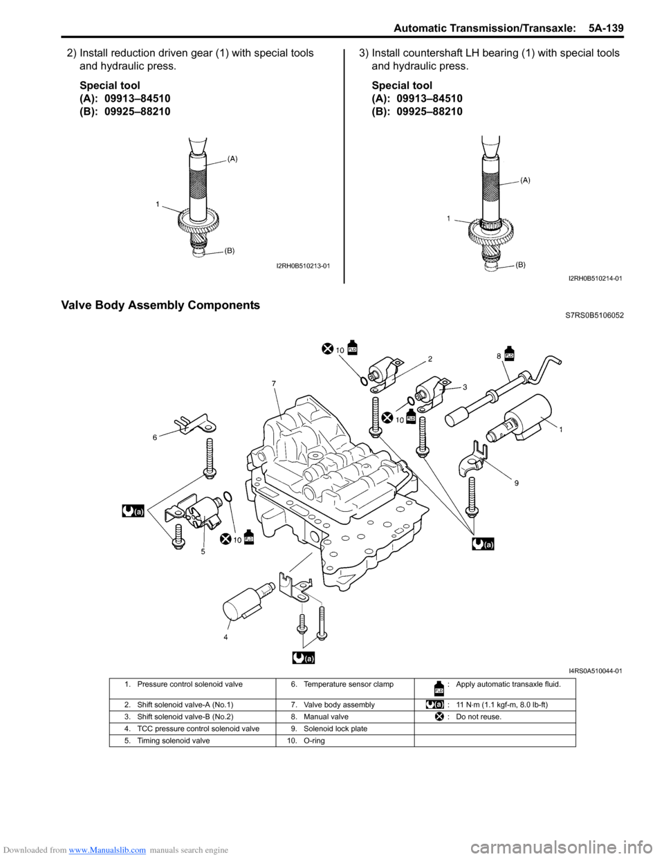
Valve Body Assembly ComponentsS7RS0B5106052
I2RH0B510213-01
I2RH0B510214-01
I4RS0A510044-01
1. Pressure control solenoid valve 6. Temperature sensor clamp : Apply automatic transaxle fluid.
2. Shift solenoid valve-A (No.1) 7. Valve body assembly: 11 N⋅m (1.1 kgf-m, 8.0 lb-ft)
3. Shift solenoid valve-B (No.2) 8. Manual valve: Do not reuse.
4. TCC pressure control solenoid valve 9. Solenoid lock plate
5. Timing solenoid valve 10. O-ring
Page 786 of 1496
Downloaded from www.Manualslib.com manuals search engine 5A-142 Automatic Transmission/Transaxle:
Differential Assembly Disassembly and
Reassembly
S7RS0B5106055
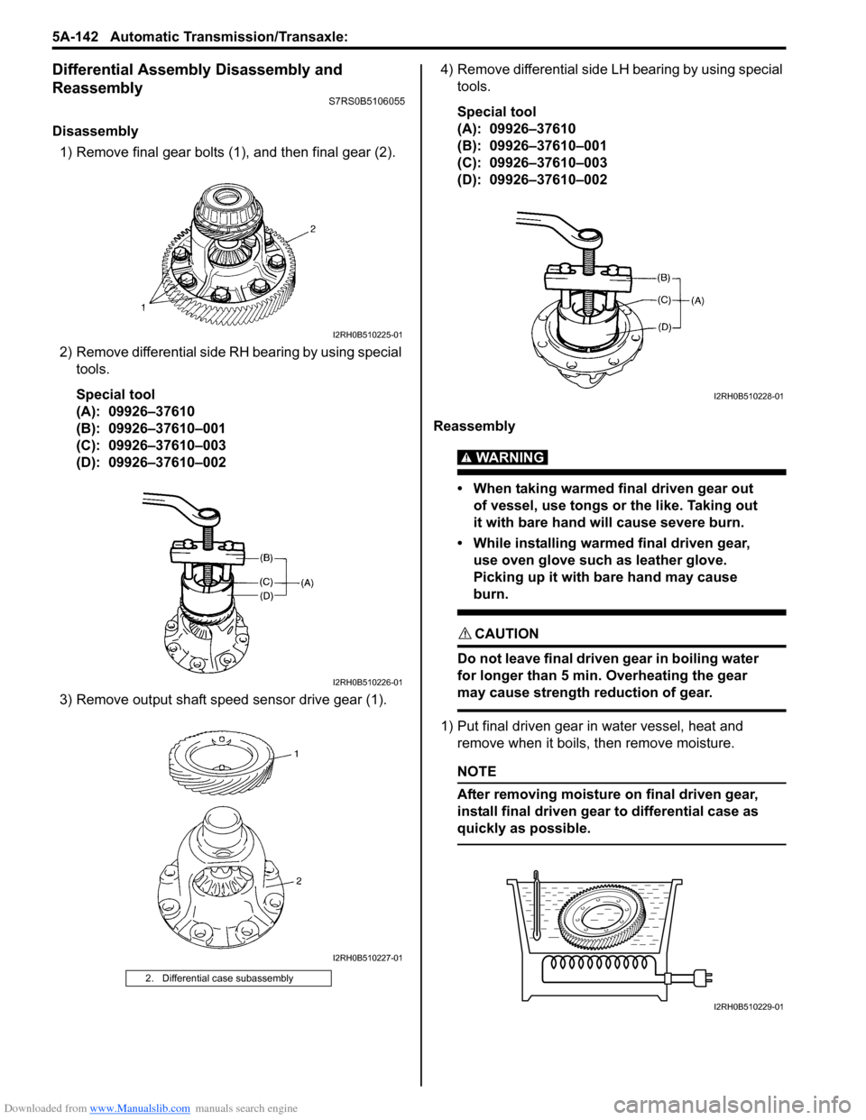
Disassembly1) Remove final gear bolts (1), and then final gear (2).
2) Remove differential side RH bearing by using special tools.
Special tool
(A): 09926–37610
(B): 09926–37610–001
(C): 09926–37610–003
(D): 09926–37610–002
3) Remove output shaft speed sensor drive gear (1). 4) Remove differential side LH bearing by using special
tools.
Special tool
(A): 09926–37610
(B): 09926–37610–001
(C): 09926–37610–003
(D): 09926–37610–002
Reassembly
WARNING!
• When taking warmed final driven gear out of vessel, use tongs or the like. Taking out
it with bare hand will cause severe burn.
• While installing warme d final driven gear,
use oven glove such as leather glove.
Picking up it with bare hand may cause
burn.
CAUTION!
Do not leave final driven gear in boiling water
for longer than 5 min. Overheating the gear
may cause strength reduction of gear.
1) Put final driven gear in water vessel, heat and remove when it boils, then remove moisture.
NOTE
After removing moisture on final driven gear,
install final driven gear to differential case as
quickly as possible.
2. Differential case subassembly
I2RH0B510225-01
I2RH0B510226-01
I2RH0B510227-01
I2RH0B510228-01
I2RH0B510229-01
Page 787 of 1496
Downloaded from www.Manualslib.com manuals search engine Automatic Transmission/Transaxle: 5A-143
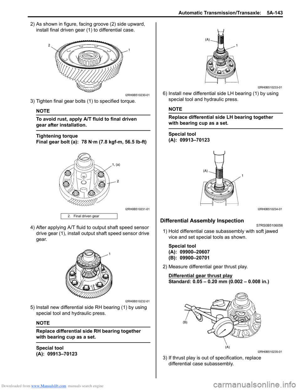
2) As shown in figure, facing groove (2) side upward, install final driven gear (1) to differential case.
3) Tighten final gear bolts (1) to specified torque.
NOTE
To avoid rust, apply A/T fluid to final driven
gear after installation.
Tightening torque
Final gear bolt (a): 78 N·m (7.8 kgf-m, 56.5 lb-ft)
4) After applying A/T fluid to output shaft speed sensor drive gear (1), install output shaft speed sensor drive
gear.
5) Install new differential side RH bearing (1) by using special tool and hydraulic press.
NOTE
Replace differential side RH bearing together
with bearing cup as a set.
Special tool
(A): 09913–70123 6) Install new differential side LH bearing (1) by using
special tool and hydraulic press.
NOTE
Replace differential side LH bearing together
with bearing cup as a set.
Special tool
(A): 09913–70123
Differential Assembly InspectionS7RS0B5106056
1) Hold differential case subassembly with soft jawed
vice and set special tools as shown.
Special tool
(A): 09900–20607
(B): 09900–20701
2) Measure differential gear thrust play.
Differential gear thrust play
Standard: 0.05 – 0.20 mm (0.002 – 0.008 in.)
3) If thrust play is out of specification, replace differential case subassembly.
2. Final driven gear
I2RH0B510230-01
I2RH0B510231-01
I2RH0B510232-01
I2RH0B510233-01
I2RH0B510234-01
I2RH0B510235-01