generator SUZUKI SWIFT 2007 2.G Service Repair Manual
[x] Cancel search | Manufacturer: SUZUKI, Model Year: 2007, Model line: SWIFT, Model: SUZUKI SWIFT 2007 2.GPages: 1496, PDF Size: 34.44 MB
Page 1203 of 1496
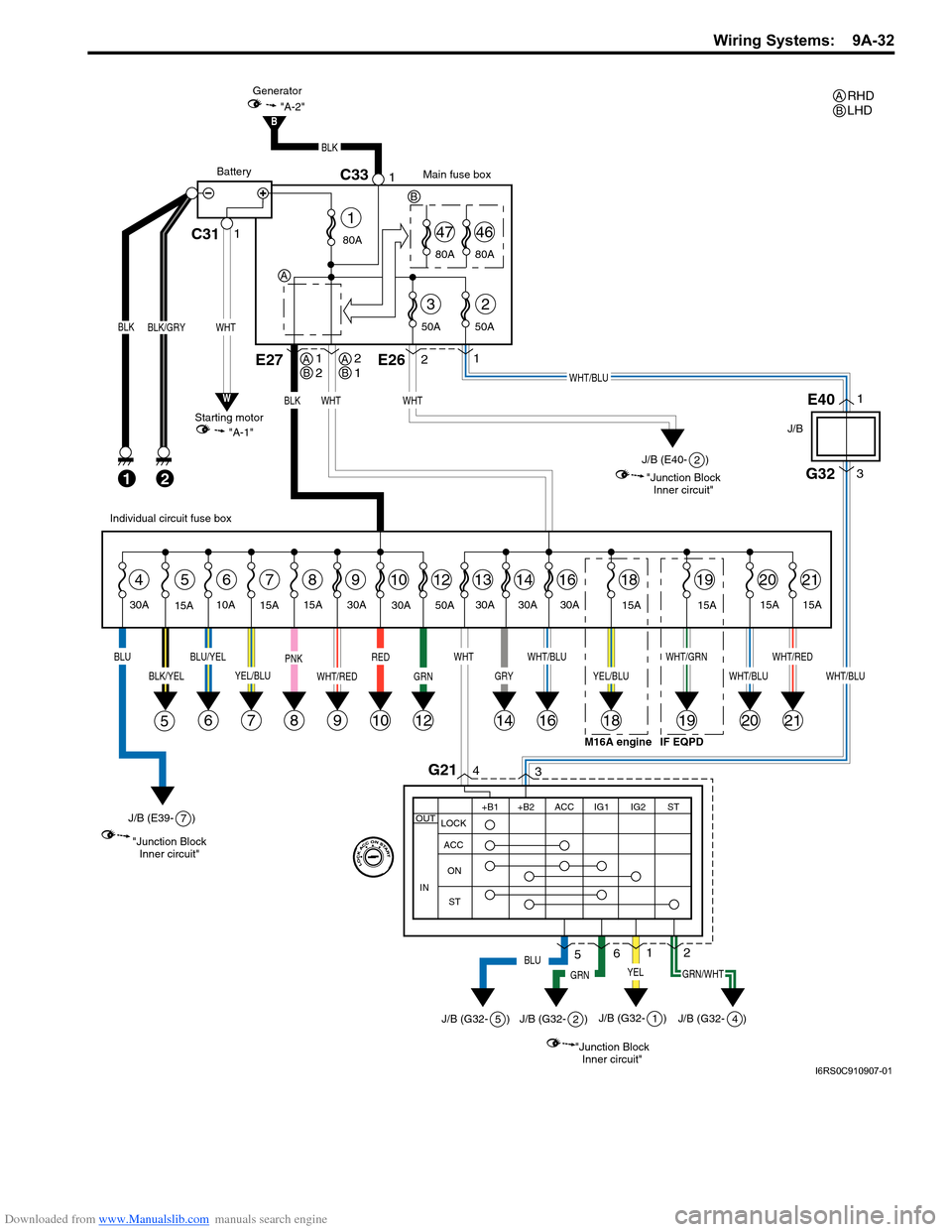
Downloaded from www.Manualslib.com manuals search engine Wiring Systems: 9A-32
G32
J/B
3
WHT/BLU
4G213
12
10
BLK
21
BLK/GRY
10A
15A30A
5647891012
E27
WHT
131416192021
BLUBLU/YEL
6
BLK/YEL
5
YEL/BLU
7
PNK
89
WHT/RED
RED
GRN
12
WHT
GRY
14
WHT/GRN
19
WHT/BLU
2021
WHT/REDWHT/BLU
16
15A
15A 30A 50A
30A
30A 30A
30A
15A15A
15A
BLK
2E261
WHT/BLU
C31 C331 1
WHT
BLK
Main fuse box
Starting motor "A-1"
Generator
"A-2"
Battery
80A
50A
50A
3
80A
47
80A
46
2
1
E401WHT
"Junction Block
Inner circuit"
J/B (E40- )
YEL
"Junction BlockInner circuit"
J/B (G32- )
2
1
"Junction BlockInner circuit"
J/B (E39- ) 7
J/B (G32- ) 4
GRN/WHT
Individual circuit fuse box
+B1
LOCK
ACC
ON
ST ACC IG1 IG2
STOUT
IN
+B2
6
GRN
J/B (G32- )
2
5BLU
J/B (G32- )5
IF EQPD
18
YEL/BLU
18
15A
M16A engine
W
B
RHD
LHDAB
A
A
B1 2AB21
B
I6RS0C910907-01
Page 1204 of 1496
Downloaded from www.Manualslib.com manuals search engine 9A-33 Wiring Systems:
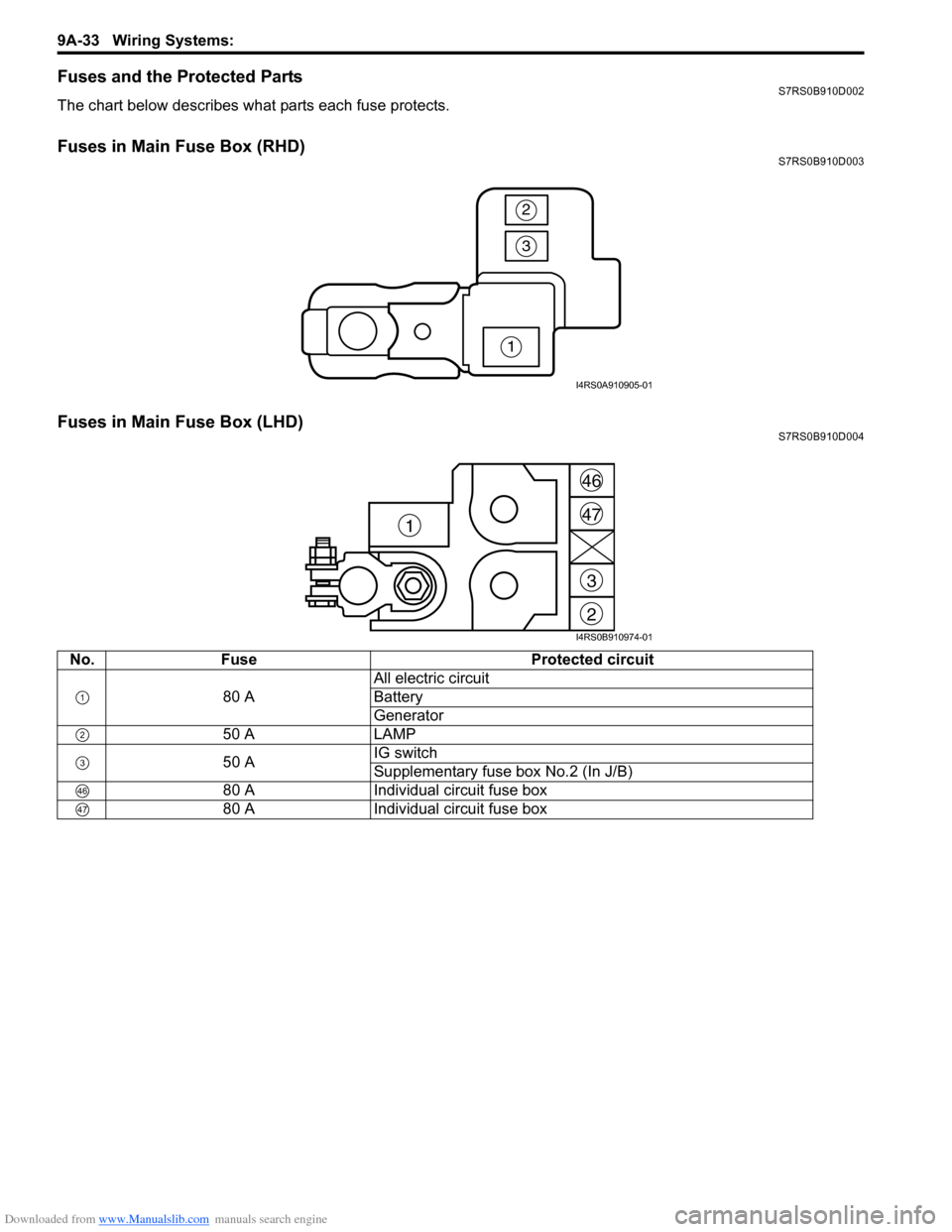
Fuses and the Protected PartsS7RS0B910D002
The chart below describes what parts each fuse protects.
Fuses in Main Fuse Box (RHD)S7RS0B910D003
Fuses in Main Fuse Box (LHD)S7RS0B910D004
No.Fuse Protected circuit
80 A All electric circuit
Battery
Generator
50 A LAMP
50 A IG switch
Supplementary fuse box No.2 (In J/B)
80 A Individual circuit fuse box
80 A Individual circuit fuse box
1
3
2
I4RS0A910905-01
2
3
47
46
1
I4RS0B910974-01
Page 1206 of 1496
Downloaded from www.Manualslib.com manuals search engine 9A-35 Wiring Systems:
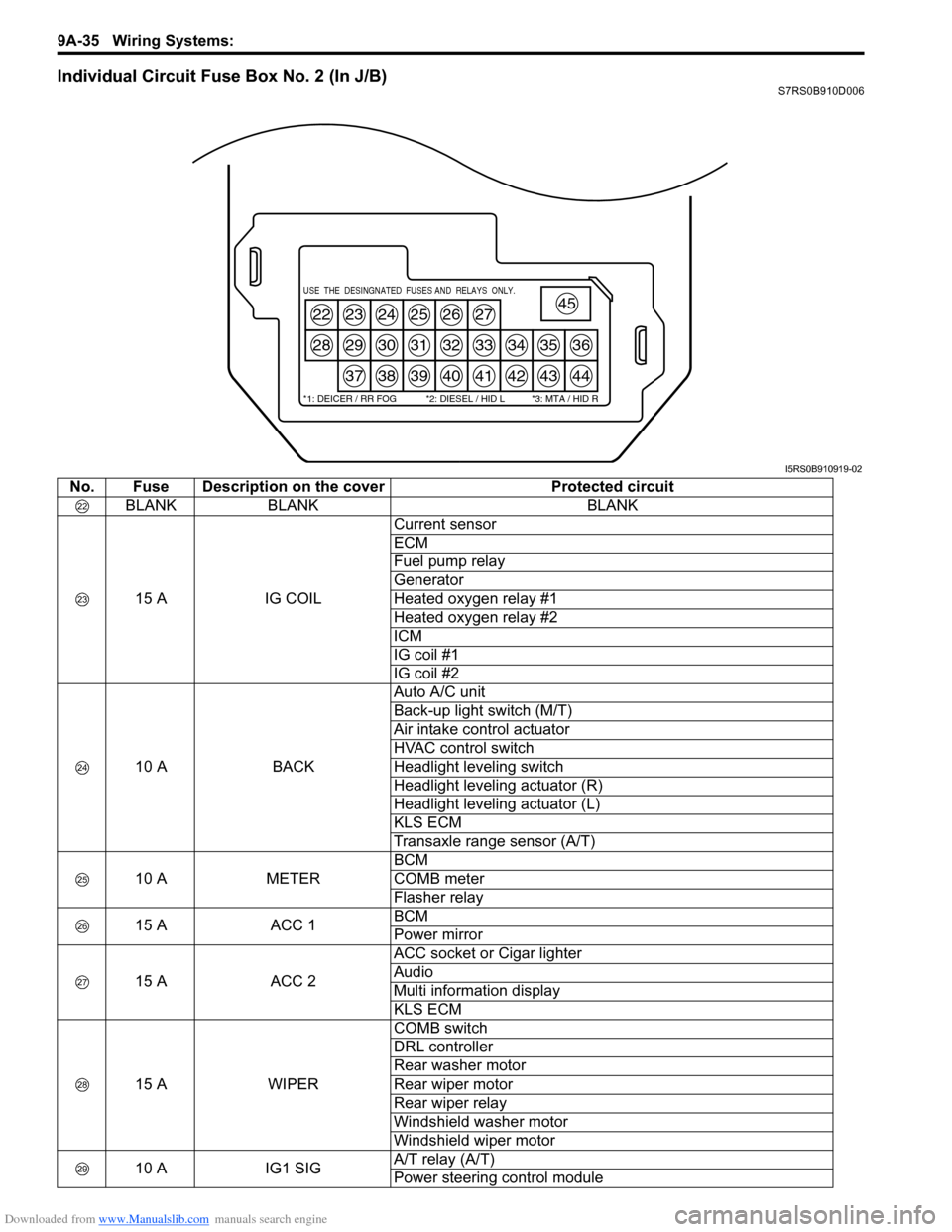
Individual Circuit Fuse Box No. 2 (In J/B)S7RS0B910D006
22
28
23
29
37
24
30
38
25
31
39
26
32
40
27
33
41
34
42
35
43
36
44
45USE THE DESINGNATED FUSES AND RELAYS ONLY.
*1: DEICER / RR FOG *2: DIESEL / HID L *3: MTA / HID R
I5RS0B910919-02
No. Fuse Description on the coverProtected circuit
BLANK BLANK BLANK
15 A IG COILCurrent sensor
ECM
Fuel pump relay
Generator
Heated oxygen relay #1
Heated oxygen relay #2
ICM
IG coil #1
IG coil #2
10 A BACKAuto A/C unit
Back-up light switch (M/T)
Air intake control actuator
HVAC control switch
Headlight leveling switch
Headlight leveling actuator (R)
Headlight leveling actuator (L)
KLS ECM
Transaxle range sensor (A/T)
10 A METERBCM
COMB meter
Flasher relay
15 A ACC 1BCM
Power mirror
15 A ACC 2ACC socket or Cigar lighter
Audio
Multi information display
KLS ECM
15 A WIPERCOMB switch
DRL controller
Rear washer motor
Rear wiper motor
Rear wiper relay
Windshield washer motor
Windshield wiper motor
10 A IG1 SIGA/T relay (A/T)
Power steering control module
Page 1218 of 1496
Downloaded from www.Manualslib.com manuals search engine 9A-47 Wiring Systems:
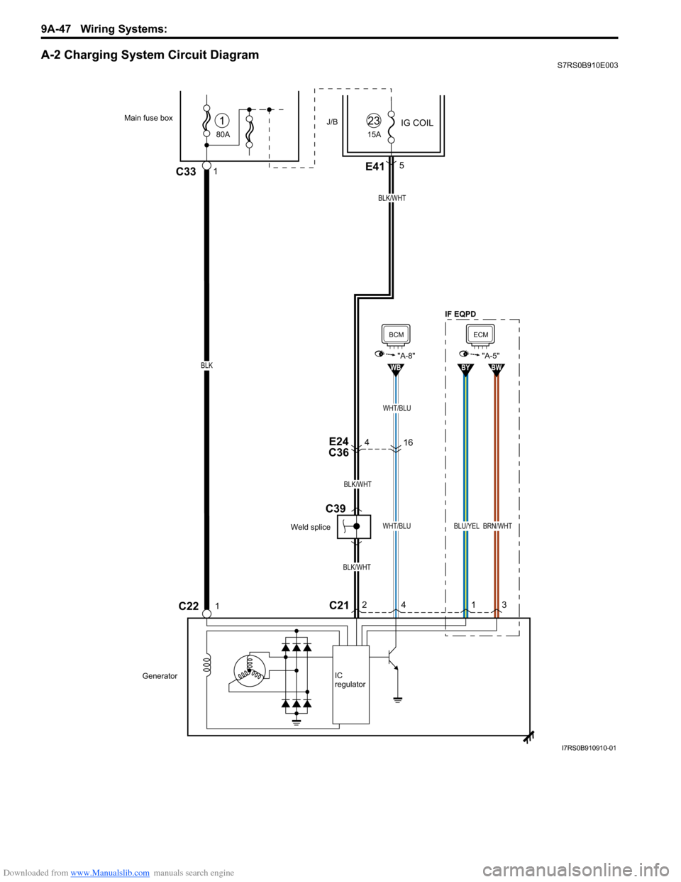
A-2 Charging System Circuit DiagramS7RS0B910E003
4E24
C36
BLK/WHT
BLK/WHT
BLK/WHT
80A
Main fuse box
C22
J/B
1C33
IG COIL1
15A
23
GeneratorIC
regulator
1
E415
C212
4
WHT/BLU
WB
BCM
"A-8"
1
BLU/YEL
BY
3
BRN/WHT
BW
ECM
"A-5"
16
WHT/BLU
BLK
Weld splice
C39
IF EQPD
I7RS0B910910-01
Page 1224 of 1496
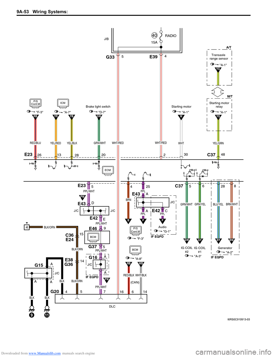
Downloaded from www.Manualslib.com manuals search engine 9A-53 Wiring Systems:
J/C
E43
J/C
G16
DLC
G20
G375
E469
E38
G3614
C36 E2415
BLK/ORN
BLK/ORN
BLK/ORN
4
BLK
11
J/C
G15
5
4
516
WHT/RED
C37
GRN/YELGRN/WHT
5 6
YG
BRN
B
P/S
Cont.M
4
"F-3"
25
A
A D
E
AA
PPL/WHT
PPL/WHT
PPL/WHT
PPL/WHT
YEL/GRNWHT/RED
BLK
9
A
PPL
E42
PPLJ/C
ECM
E394
J/B15A RADIO
40
E23
E23
YEL/BLKYEL/REDRED/BLU
13
282620
BLK
2C37
M/T
A/T
48
W
WHT
30
GYGW
BRN/WHTBLU/YEL
28
8
BWBY
IG COIL
#1 Generator
IG COIL
#2
(CAN) "A-3""A-2"
Audio
"G-1"
GRN/WHT
P
7
BCM
Starting motor relay
"A-1"
Transaxle
range sensor
YG"A-1"
ICM
"A-7"
P/S
Cont.M
"F-3"YBYRRBGW"D-7"
Brake light switch
"A-1"Starting motor
PW
PW
G335
WHT/BLKRED/BLK
RBWB
"A-8"
14
6
BCM
A
J/C
E43
APPL
P
E42C
IF EQPD IF EQPD
IF EQPD
I6RS0C910913-03
Page 1232 of 1496
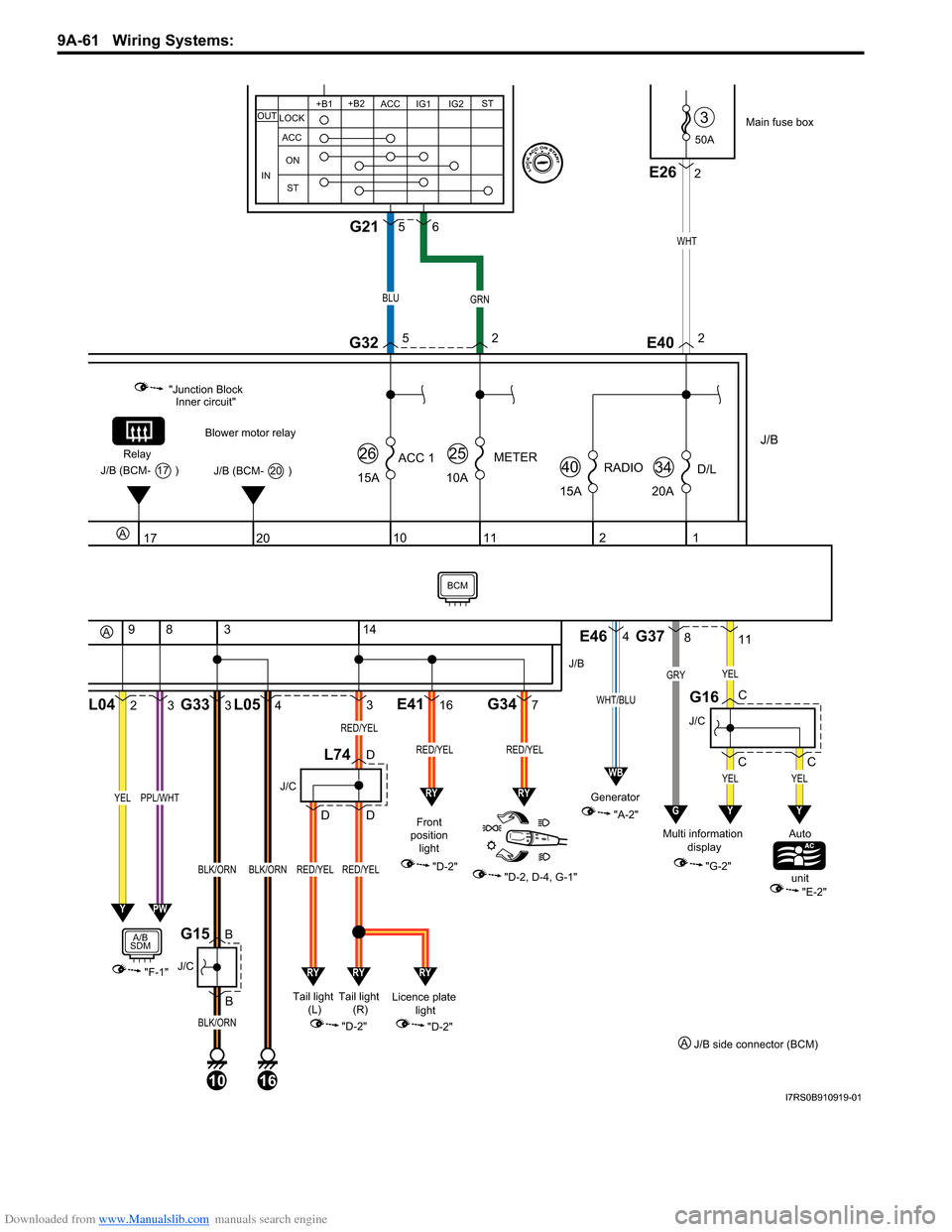
Downloaded from www.Manualslib.com manuals search engine 9A-61 Wiring Systems:
50A
3
J/B
15ARADIO
40
2
15A
ACC 1
26
10
1
20AD/L
34
11
10A
METER
25
Main fuse box
WHT
E402
20
Blower motor relay
"Junction Block Inner circuit"
Relay
J/B (BCM- 20 )J/B (BCM- 17 )
17
2L04
9
3
83
B BG33
3
4L05
10
J/C
G15
BLK/ORN
BLK/ORN
16
BLK/ORN
"F-1"
YELPPL/WHT
A/B
SDM
14
316E417G34
Front
position light
"D-2"
"D-2, D-4, G-1"
J/B
RED/YELRED/YEL
J/C
L74D
DD
Licence plate light
"D-2"
YPW
"A-2"
Generator
E464
WHT/BLU
WB
RYRY
RYRYRY
Tail light
(R)
Tail light
(L)
"D-2"
RED/YEL
RED/YEL
RED/YEL
811
C CG37
J/C
G16
YEL
GRYYEL
GY
C
YEL
Y
"G-2"
Multi information
display Auto
unit
"E-2"
A
A
J/C
2E26
+B1
LOCK
ACC
ON
ST ACC IG1 IG2
STOUT
IN
+B2
BLUGRN
G3252
56G21
J/B side connector (BCM)
A
BCM
I7RS0B910919-01
Page 1284 of 1496
Downloaded from www.Manualslib.com manuals search engine 9B-2 Lighting Systems:
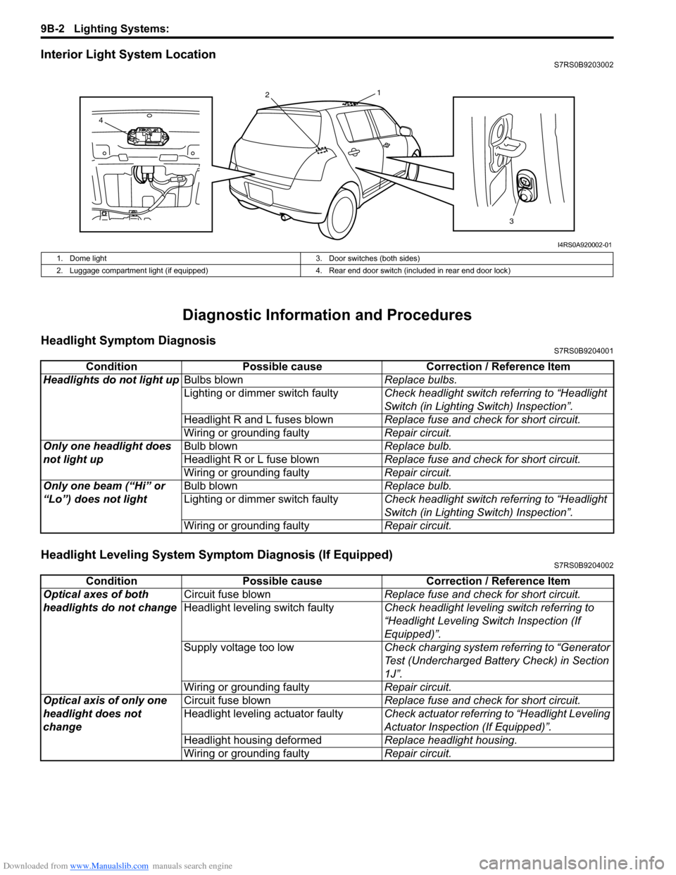
Interior Light System LocationS7RS0B9203002
Diagnostic Information and Procedures
Headlight Symptom DiagnosisS7RS0B9204001
Headlight Leveling System Symptom Diagnosis (If Equipped)S7RS0B9204002
13
2
4
I4RS0A920002-01
1. Dome light 3. Door switches (both sides)
2. Luggage compartment light (if equipped) 4. Rear end door switch (included in rear end door lock)
ConditionPossible cause Correction / Reference Item
Headlights do not light up Bulbs blown Replace bulbs.
Lighting or dimmer switch faulty Check headlight switch referring to “Headlight
Switch (in Lighting Switch) Inspection”.
Headlight R and L fuses blown Replace fuse and check for short circuit.
Wiring or grounding faulty Repair circuit.
Only one headlight does
not light up Bulb blown
Replace bulb.
Headlight R or L fuse blown Replace fuse and check for short circuit.
Wiring or grounding faulty Repair circuit.
Only one beam (“Hi” or
“Lo”) does not light Bulb blown
Replace bulb.
Lighting or dimmer switch faulty Check headlight switch referring to “Headlight
Switch (in Lighting Switch) Inspection”.
Wiring or grounding faulty Repair circuit.
ConditionPossible cause Correction / Reference Item
Optical axes of both
headlights do not change Circuit fuse blown
Replace fuse and check for short circuit.
Headlight leveling switch faulty Check headlight leveling switch referring to
“Headlight Leveling Switch Inspection (If
Equipped)”.
Supply voltage too low Check charging system referring to “Generator
Test (Undercharged Battery Check) in Section
1J”.
Wiring or grounding faulty Repair circuit.
Optical axis of only one
headlight does not
change Circuit fuse blown
Replace fuse and check for short circuit.
Headlight leveling actuator faulty Check actuator referring to “Headlight Leveling
Actuator Inspection (If Equipped)”.
Headlight housing deformed Replace headlight housing.
Wiring or grounding faulty Repair circuit.
Page 1409 of 1496
![SUZUKI SWIFT 2007 2.G Service Repair Manual Downloaded from www.Manualslib.com manuals search engine Body Electrical Control System: 10B-6
[A]: Vehicle not equipped with diagnosis connector 19. Door key cylinder switch (included in door lock a SUZUKI SWIFT 2007 2.G Service Repair Manual Downloaded from www.Manualslib.com manuals search engine Body Electrical Control System: 10B-6
[A]: Vehicle not equipped with diagnosis connector 19. Door key cylinder switch (included in door lock a](/img/20/7607/w960_7607-1408.png)
Downloaded from www.Manualslib.com manuals search engine Body Electrical Control System: 10B-6
[A]: Vehicle not equipped with diagnosis connector 19. Door key cylinder switch (included in door lock actuator)40. SDM
[B]: Vehicle equipped with diagnosis conn ector 20. Manual door lock switch 41. Rear end door window defogger relay
[C]: ESP ® model 21. Rear end door window defogger switch 42. Rear end door window defogger
1. BCM (included in junction block assembly) 22. Rear end door opener switch 43. Rear end door window defogger indicator lamp
2. Rear washer motor 23. “3” position switch (A/T model)44. Horn relay
3. Rear wiper motor 24. A/C switch45. Horn switch
4. Rear wiper relay 25. Rear end door opener relay46. Horn
5. Rear wiper and washer switch 26. Rear end door opener actuator47. Lighting switch
6. Outside air temperature sensor 27. TCM (A/T model)48. Ignition switch
7. Key reminder switch 28. ECM49. Battery
8. Theft deterrent light 29. Combination meter50. To turn signal light
9. Oil pressure switch 30. Data link connector (DLC)51. Body ground
10. Generator 31. To ECM, ABS/ESP®, P/S control module 52. Engine ground
11. Information display (if equipped) 32. To SDM53. Keyless start control module (if equipped)
12. Keyless entry receiver (if equipped) 33. Door lock actuator relay 54. Right side door mirror heater (if equipped)
13. Driver side door switch 34. Driver side door lock actuator55. Left side door mirror heater (if equipped)
14. Other than driver side door switch 35. Passenger side door lock actuator56. ABS/ESP® control module
15. Rear end door switch 36. Rear door lock actuator57. To HVAC control module
16. Driver side seat belt switch 37. Turn signal and hazard warning relay 58. CAN junction connector
17. Brake fluid level switch 38. Hazard warning switch59. Steering angle sensor
18. Parking brake switch 39. Interior light
Page 1411 of 1496
Downloaded from www.Manualslib.com manuals search engine Body Electrical Control System: 10B-8
Component Location
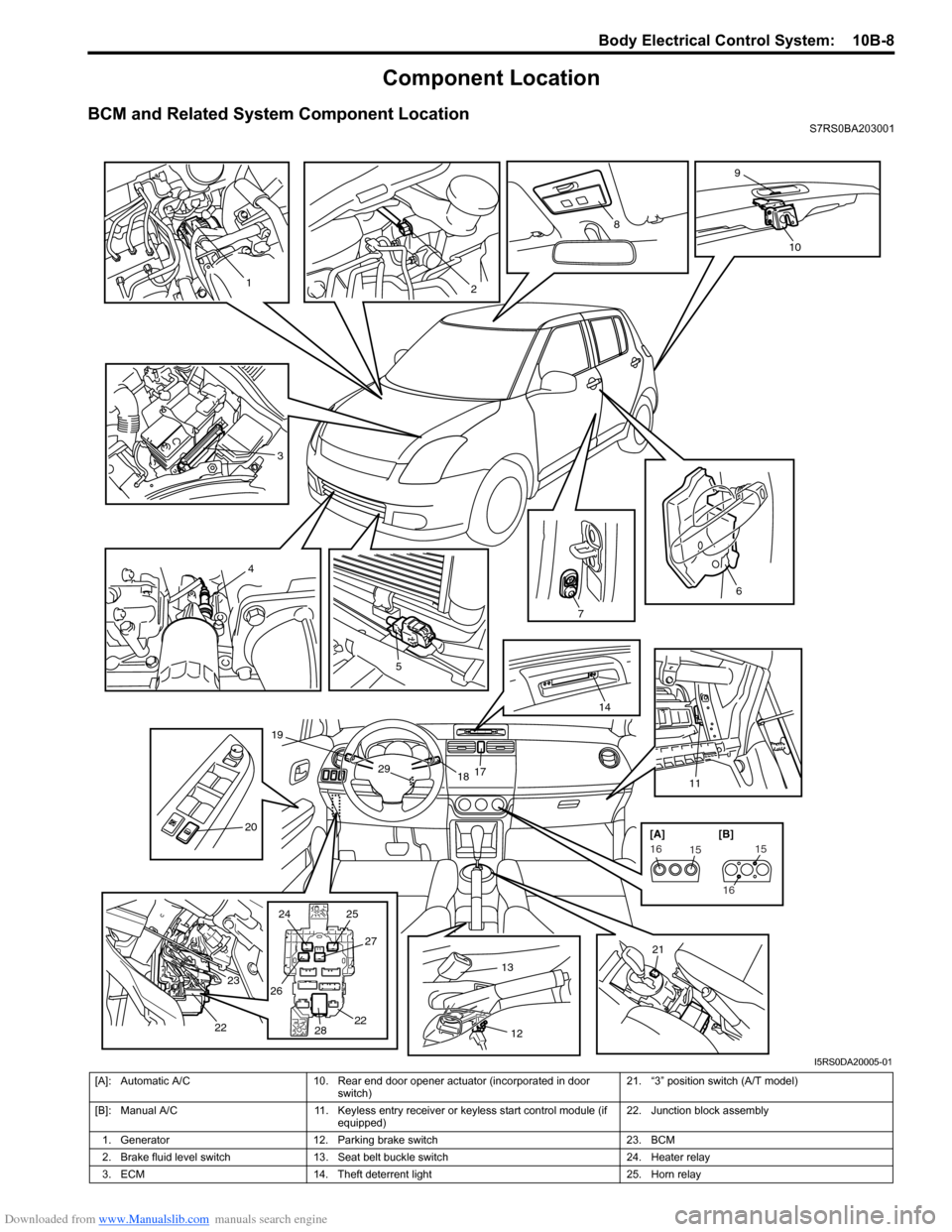
BCM and Related System Component LocationS7RS0BA203001
3
4
5
7
6
1117
1829
19
14
20
21
24
25
26 27
28 22
23
22
1
2
8
9
10
1312
151615
16
[A] [B]
I5RS0DA20005-01
[A]: Automatic A/C
10. Rear end door opener actuator (incorporated in door
switch) 21. “3” position switch (A/T model)
[B]: Manual A/C 11. Keyless entry receiver or keyless start control module (if
equipped) 22. Junction block assembly
1. Generator 12. Parking brake switch 23. BCM
2. Brake fluid level switch 13. Seat belt buckle switch 24. Heater relay
3. ECM 14. Theft deterrent light 25. Horn relay
Page 1412 of 1496
Downloaded from www.Manualslib.com manuals search engine 10B-9 Body Electrical Control System:
Diagnostic Information and Procedures
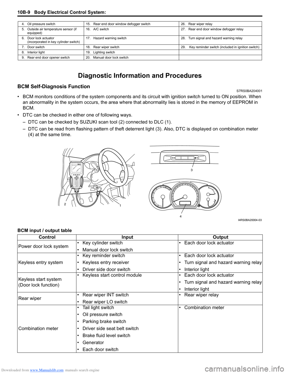
BCM Self-Diagnosis FunctionS7RS0BA204001
• BCM monitors conditions of the system components and its circuit with ignition switch turned to ON position. When
an abnormality in the system oc curs, the area where that abnormality lies is stored in the memory of EEPROM in
BCM.
• DTC can be checked in either one of following ways. – DTC can be checked by SUZUKI scan tool (2) connected to DLC (1).
– DTC can be read from flashing pattern of theft deterrent light (3). Also, DTC is displayed on combination meter
(4) at the same time.
BCM input / output table
4. Oil pressure switch 15. Rear end door window defogger switch 26. Rear wiper relay
5. Outside air temperature sensor (if equipped) 16. A/C switch
27. Rear end door window defogger relay
6. Door lock actuator (incorporated in key cylinder switch) 17. Hazard warning switch
28. Turn signal and hazard warning relay
7. Door switch 18. Rear wiper switch 29. Key reminder switch (included in ignition switch)
8. Interior light 19. Lighting switch
9. Rear end door opener switch 20. Manual door lock switch
3
1
2
4I4RS0BA20004-03
Control
Input Output
Power door lock system • Key cylinder switch
• Manual door lock switch • Each door lock actuator
Keyless entry system • Key reminder switch
• Keyless entry receiver
• Driver side door switch • Each door lock actuator
• Turn signal and hazard warning relay
• Interior light
Keyless start system
(Door lock function) • Keyless start control module
• Each door lock actuator
• Turn signal and hazard warning relay
• Interior light
Rear wiper • Rear wiper INT switch
• Rear wiper LO switch • Rear wiper relay
Combination meter • Tail light switch
• Oil pressure switch
• Parking brake switch
• Driver side seat belt switch
• Brake fluid level switch
• Generator
• Each door switch • Combination meter