refrigerant SUZUKI SWIFT 2007 2.G Service Manual PDF
[x] Cancel search | Manufacturer: SUZUKI, Model Year: 2007, Model line: SWIFT, Model: SUZUKI SWIFT 2007 2.GPages: 1496, PDF Size: 34.44 MB
Page 1014 of 1496
Downloaded from www.Manualslib.com manuals search engine 7B-66 Air Conditioning System: Automatic Type
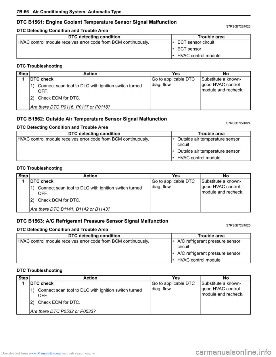
DTC B1561: Engine Coolant Temperature Sensor Signal MalfunctionS7RS0B7224023
DTC Detecting Condition and Trouble Area
DTC Troubleshooting
DTC B1562: Outside Air Temperature Sensor Signal MalfunctionS7RS0B7224024
DTC Detecting Condition and Trouble Area
DTC Troubleshooting
DTC B1563: A/C Refrigerant Pressure Sensor Signal MalfunctionS7RS0B7224025
DTC Detecting Condition and Trouble Area
DTC TroubleshootingDTC detecting condition Trouble area
HVAC control module receives error code from BCM continuously. • ECT sensor circuit
• ECT sensor
• HVAC control module
StepAction YesNo
1 DTC check
1) Connect scan tool to DLC with ignition switch turned
OFF.
2) Check ECM for DTC.
Are there DTC P0116, P0117 or P0118? Go to applicable DTC
diag. flow.
Substitute a known-
good HVAC control
module and recheck.
DTC detecting condition
Trouble area
HVAC control module receives er ror code from BCM continuously. • Outside air temperature sensor
circuit
• Outside air temperature sensor
• HVAC control module
Step Action YesNo
1 DTC check
1) Connect scan tool to DLC with ignition switch turned
OFF.
2) Check BCM for DTC.
Are there DTC B1141, B1142 or B1143? Go to applicable DTC
diag. flow.
Substitute a known-
good HVAC control
module and recheck.
DTC detecting condition
Trouble area
HVAC control module receives er ror code from BCM continuously. • A/C refrigerant pressure sensor
circuit
• A/C refrigerant pressure sensor
• HVAC control module
Step Action YesNo
1 DTC check
1) Connect scan tool to DLC with ignition switch turned
OFF.
2) Check ECM for DTC.
Are there DTC P0532 or P0533? Go to applicable DTC
diag. flow.
Substitute a known-
good HVAC control
module and recheck.
Page 1019 of 1496
Downloaded from www.Manualslib.com manuals search engine Air Conditioning System: Automatic Type 7B-71
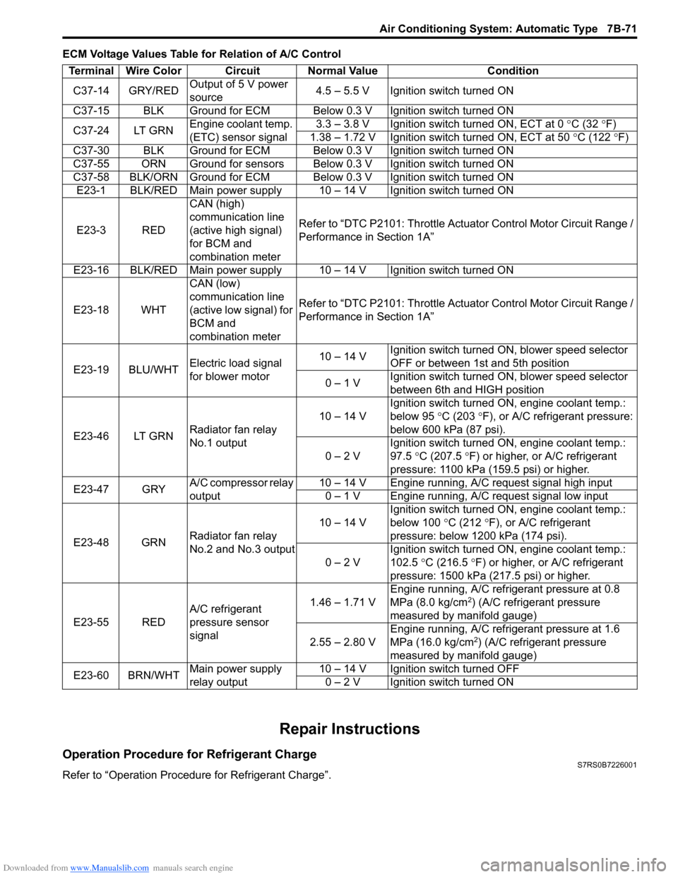
ECM Voltage Values Table for Relation of A/C Control
Repair Instructions
Operation Procedure for Refrigerant ChargeS7RS0B7226001
Refer to “Operation Procedure for Refrigerant Charge”.Terminal Wire Color Circuit Normal Value Condition
C37-14 GRY/RED Output of 5 V power
source 4.5 – 5.5 V Ignition switch turned ON
C37-15 BLK Ground for ECM Below 0.3 V Ignition switch turned ON
C37-24 LT GRN Engine coolant temp.
(ETC) sensor signal 3.3 – 3.8 V Ignition switch turned ON, ECT at 0
°C (32 ° F)
1.38 – 1.72 V Ignition switch turned ON, ECT at 50 °C (122 °F)
C37-30 BLK Ground for ECM Below 0.3 V Ignition switch turned ON
C37-55 ORN Ground for sensors Below 0.3 V Ignition switch turned ON
C37-58 BLK/ORN Ground for ECM Below 0.3 V Ignition switch turned ON E23-1 BLK/RED Main power supply 10 – 14 V Ignition switch turned ON
E23-3 RED CAN (high)
communication line
(active high signal)
for BCM and
combination meterRefer to “DTC P2101: Throttle Actu
ator Control Motor Circuit Range /
Performance in Section 1A”
E23-16 BLK/RED Main power supply 10 – 14 V Ignition switch turned ON
E23-18 WHT CAN (low)
communication line
(active low signal) for
BCM and
combination meterRefer to “DTC P2101: Throttle Actu
ator Control Motor Circuit Range /
Performance in Section 1A”
E23-19 BLU/WHT Electric load signal
for blower motor 10 – 14 V
Ignition switch turned ON, blower speed selector
OFF or between 1st and 5th position
0 – 1 V Ignition switch turned ON, blower speed selector
between 6th and HIGH position
E23-46 LT GRN Radiator fan relay
No.1 output 10 – 14 V
Ignition switch turned ON, engine coolant temp.:
below 95
°C (203 ° F), or A/C refrigerant pressure:
below 600 kPa (87 psi).
0 – 2 V Ignition switch turned ON, engine coolant temp.:
97.5
°C (207.5 °F) or higher, or A/C refrigerant
pressure: 1100 kPa (159.5 psi) or higher.
E23-47 GRY A/C compressor relay
output 10 – 14 V Engine running, A/C request signal high input
0 – 1 V Engine running, A/C request signal low input
E23-48 GRN Radiator fan relay
No.2 and No.3 output 10 – 14 V
Ignition switch turned ON, engine coolant temp.:
below 100
°C (212 °F), or A/C refrigerant
pressure: below 1200 kPa (174 psi).
0 – 2 V Ignition switch turned ON, engine coolant temp.:
102.5
°C (216.5 ° F) or higher, or A/C refrigerant
pressure: 1500 kPa (217.5 psi) or higher.
E23-55 RED A/C refrigerant
pressure sensor
signal 1.46 – 1.71 V
Engine running, A/C refrigerant pressure at 0.8
MPa (8.0 kg/cm
2) (A/C refrigerant pressure
measured by manifold gauge)
2.55 – 2.80 V Engine running, A/C refrigerant pressure at 1.6
MPa (16.0 kg/cm
2) (A/C refrigerant pressure
measured by manifold gauge)
E23-60 BRN/WHT Main power supply
relay output 10 – 14 V Ignition switch turned OFF
0 – 2 V Ignition switch turned ON
Page 1026 of 1496
Downloaded from www.Manualslib.com manuals search engine 7B-78 Air Conditioning System: Automatic Type
Inside Air Temperature Sensor Removal and
Installation
S7RS0B7226018
Removal1) Disconnect negative (–) cable at battery.
2) Remove steering column hole cover.
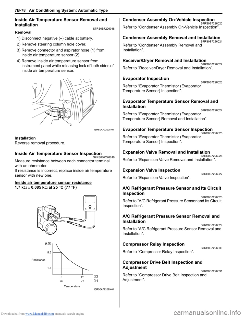
3) Remove connector and aspirator hose (1) from inside air temperature sensor (2).
4) Remove inside air temperature sensor from instrument panel while releas ing lock of both sides of
inside air temperature sensor.
Installation
Reverse removal procedure.
Inside Air Temperature Sensor InspectionS7RS0B7226019
Measure resistance between each connector terminal
with an ohmmeter.
If resistance is incorrect, replace inside air temperature
sensor with new one.
Inside air temperature sensor resistance
1.7 k Ω ± 0.085 k Ω at 25 °C (77 ° F)
Condenser Assembly On-Vehicle InspectionS7RS0B7226020
Refer to “Condenser Assembly On-Vehicle Inspection”.
Condenser Assembly Removal and InstallationS7RS0B7226021
Refer to “Condenser Assembly Removal and
Installation”.
Receiver/Dryer Removal and InstallationS7RS0B7226022
Refer to “Receiver/Dryer Removal and Installation”.
Evaporator InspectionS7RS0B7226023
Refer to “Evaporator Thermistor (Evaporator
Temperature Sensor) Inspection”.
Evaporator Temperature Sensor Removal and
Installation
S7RS0B7226024
Refer to “Evaporator Thermistor (Evaporator
Temperature Sensor) Removal and Installation”.
Evaporator Temperature Sensor InspectionS7RS0B7226025
Refer to “Evaporator Thermistor (Evaporator
Temperature Sensor) Inspection”.
Expansion Valve Removal and InstallationS7RS0B7226026
Refer to “Expansion Valve Removal and Installation”.
Expansion Valve InspectionS7RS0B7226027
Refer to “Expansion Valve Inspection”.
A/C Refrigerant Pressure Sensor and Its Circuit
Inspection
S7RS0B7226028
Refer to “A/C Refrigerant Pressure Sensor and Its Circuit
Inspection”.
A/C Refrigerant Pressure Sensor Removal and
Installation
S7RS0B7226029
Refer to “A/C Refrigerant Pressure Sensor Removal and
Installation”.
Compressor Relay InspectionS7RS0B7226030
Refer to “Compressor Relay Inspection”.
Compressor Drive Belt Inspection and
Adjustment
S7RS0B7226031
Refer to “Compressor Drive Belt Inspection and
Adjustment”.
12I5RS0A722028-01
Temperature
Resistance
1.7
0
32 25
77
F
5.5
I5RS0A722029-01
Page 1223 of 1496
Downloaded from www.Manualslib.com manuals search engine Wiring Systems: 9A-52
"E-1"
"E-2"
EGR
stepper motor
PPL
P
"A-6"
AB
AB
CD
CD
ECM
2
3
REDORNGRY/RED
EVAP
thermistor
1
2G09
13
ORN
ORN
E38
G36
BW
Blower
speed
selector
Auto
unit
A/C refrigerant
pressure sensor
E04
C10
BRN/YEL
WHT/REDGRN/RED
6
4312
5
CKP
sensor CMP
sensor VSS
TCM
C37
BLK
3
155830
C25
21
3CDE12CDE23 3
1
CDE31
1 2
3
C08
C20
C37
18 19
4320
219
PNK
RED/YEL
E2354
55
C36
E2410
1
2
3
19
4
RED/WHT
49
BLK/RED
BLK
C012
1 3
IAC
valve
BLU/WHT
GRN/ORN
WHT/BLK
57
4
WHT/BLK
BLK/RED
BLK/ORNBLK/ORNBLK/ORNBLK/ORN
C40Weld splice
BLK/ORNBLK/ORN
C38Weld splice
BLK/REDBLK/RED
BLK/REDBLK/RED
M13A engine M/T, M15A engine M/T
A/T
M13A engine
M15A engine
M16A engine
ABCDE
Manual A/C
Auto A/C
I7RS0B910941-01
Page 1405 of 1496
Downloaded from www.Manualslib.com manuals search engine Body Electrical Control System: 10B-2
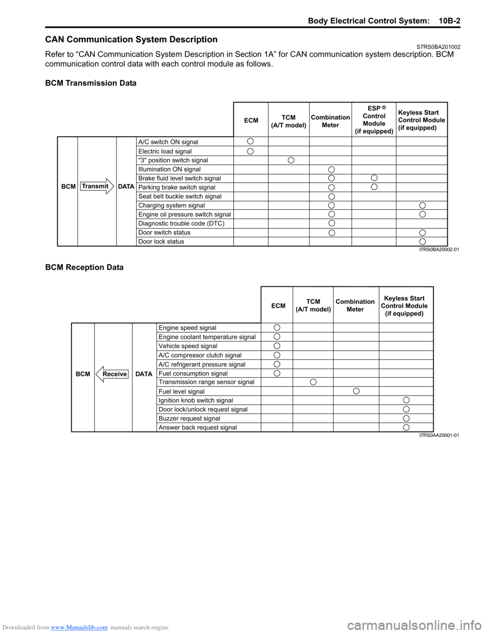
CAN Communication System DescriptionS7RS0BA201002
Refer to “CAN Communication System Description in Section 1A” for CAN communication system description. BCM
communication control data with ea ch control module as follows.
BCM Transmission Data
BCM Reception Data
A/C switch ON signal
Electric load signal
"3" position switch signal
Illumination ON signal
Brake fluid level switch signal
Parking brake switch signal
Seat belt buckle switch signal
Charging system signal
Engine oil pressure switch signal
Diagnostic trouble code (DTC)
Door switch status
Door lock status ECM
TCM
(A/T model) Combination
Meter Keyless Start
Control Module
(if equipped)
Transmit DATA
BCM
ESP
Control Module
(if equipped)
I7RS0BA20002-01
Engine speed signal
Vehicle speed signal Engine coolant temperature signal
A/C refrigerant pressure signal
Fuel consumption signal A/C compressor clutch signal
Transmission range sensor signal
Fuel level signal
Ignition knob switch signal
Door lock/unlock request signal
Buzzer request signal
Answer back request signal
DATA
BCM
Receive
Combination
Meter
TCM
(A/T model) Keyless Start
Control Module (if equipped)
ECM
I7RS0AA20001-01