low SUZUKI SWIFT 2007 2.G Service Workshop Manual
[x] Cancel search | Manufacturer: SUZUKI, Model Year: 2007, Model line: SWIFT, Model: SUZUKI SWIFT 2007 2.GPages: 1496, PDF Size: 34.44 MB
Page 1248 of 1496
Downloaded from www.Manualslib.com manuals search engine 9A-77 Wiring Systems:
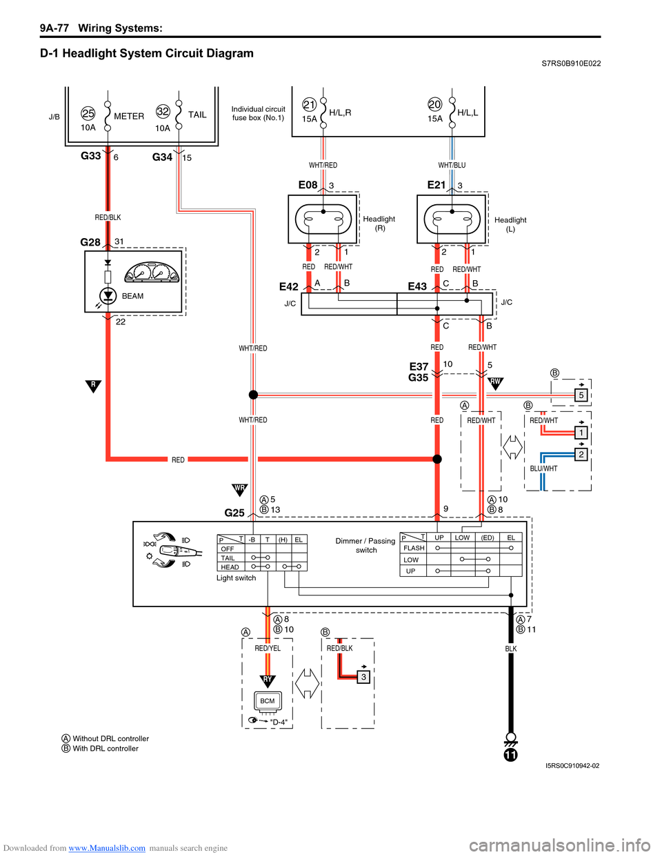
D-1 Headlight System Circuit DiagramS7RS0B910E022
1
Headlight (R) Headlight
(L)
WHT/BLU
RED
Dimmer / Passing switch
Light switch
2
2
BA BC
B
C
33
15
1
22G28
E08
G34
E21
G336
31
RED/BLK
WHT/RED
WHT/RED
10A
25METER
WHT/RED
9
BLK
11
G25
15A
21
15A
20H/L,R H/L,L
RED/WHTRED
10
RED
RED
J/B
10ATAIL
32
RED/WHTRED/WHT
BLU/WHT
5
RED/WHT
E37
G35
E42
J/C
REDRED/WHT
BEAM
FLASH UPLOW
T
P(ED)EL
UP
LOW
OFF
TAIL
HEAD -BT
T
P(H) EL
RY
RED/YEL
"D-4"
BCM
R
WR
RW
E43
J/C
Individual circuit
fuse box (No.1)
Without DRL controller
AWith DRL controller
B
A
5
1
2
3
AB
B
RED/BLK
B
AB5
13AB10
8
AB7
11AB8
10
I5RS0C910942-02
Page 1261 of 1496
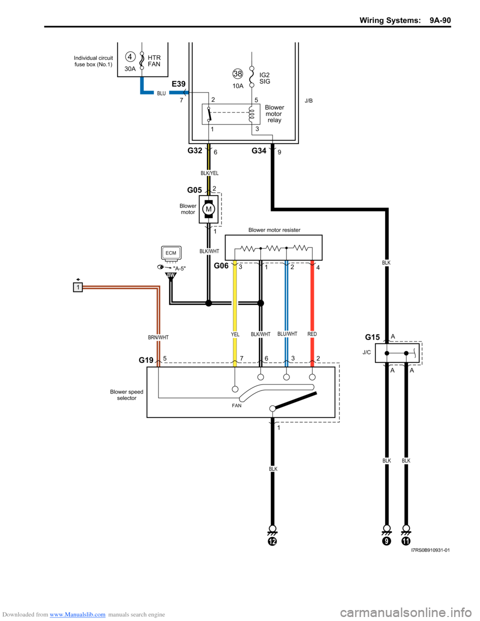
Downloaded from www.Manualslib.com manuals search engine Wiring Systems: 9A-90
RED
M
YELBLU/WHTBLK/WHT
G195
BRN/WHT
J/B
BLK/WHT
BLK/YEL
1
2G05
12
BLK
G06
Blower motor resister
1
3
4
2
Blower
motor
G326
1
72
3
6
FAN
ECM
"A-5"BW
Blower speed
selector
12
5
3
30A HTR
FAN
4
10A
38IG2
SIG
Blowermotor relay
E39
7
G349
G15
J/C
9
A
A
A
BLK
BLK
11
BLK
BLU
1
Individual circuit fuse box (No.1)
I7RS0B910931-01
Page 1263 of 1496
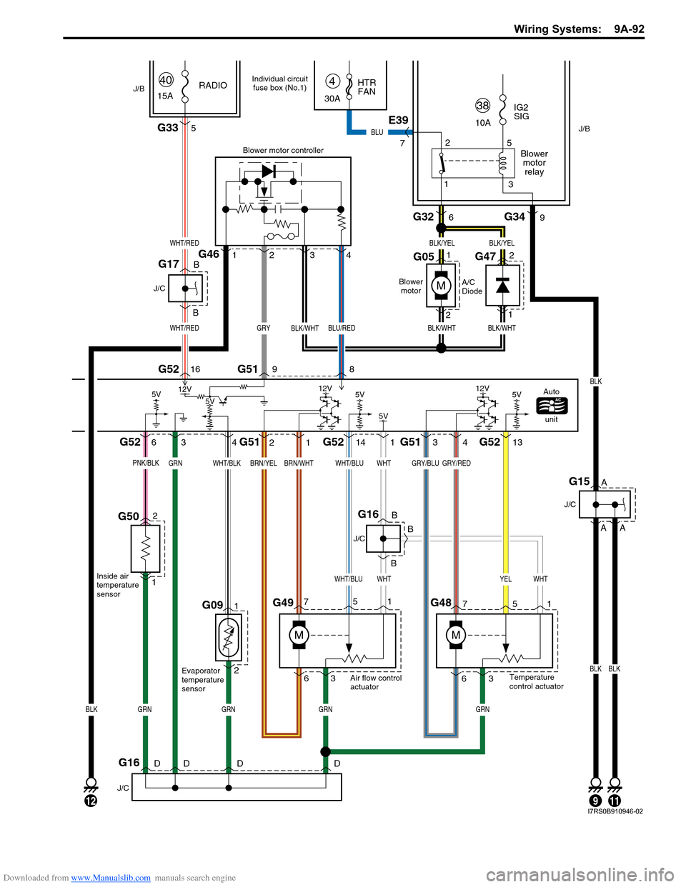
Downloaded from www.Manualslib.com manuals search engine Wiring Systems: 9A-92
G091
2
346
1698G52 G51
G52 G52
G51 G51G52
1
3
7
G495
6
M
G48
M
2
31141413
341
M
2G46
5G33
WHT/RED
WHT/RED
BLK/WHT
GRY/REDGRY/BLUWHTWHT/BLUBRN/WHTBRN/YELWHT/BLKGRN
WHTYELWHTWHT/BLU
GRNGRNBLKGRNGRN
BLK/YELBLK/YEL
BLK/WHTGRYBLK/WHTBLU/RED
Blower motor controller
A/C
DiodeAutounit
Blower
motor
15A RADIO
Evaporator
temperature
sensor Air flow control
actuator
Temperature
control actuator
40
635
71 2
G47
G051
2 1
5V5V
5V5V 12V
12V
12V
J/B
J/B
G326
1 2
5
3
30A HTR
FAN
4
10A
38IG2
SIG
Blowermotorrelay
E39
7
G349
G15
J/C
912
A
A
BLK
11
A
BLKBLK
BLU
J/C
B BG16
B
G16
J/C
DDDD
G17
J/C
B
B
Individual circuit fuse box (No.1)
G502
1
PNK/BLK
Inside air
temperature
sensor
5V
I7RS0B910946-02
Page 1283 of 1496
Downloaded from www.Manualslib.com manuals search engine Lighting Systems: 9B-1
Body, Cab and Accessories
Lighting Systems
Component Location
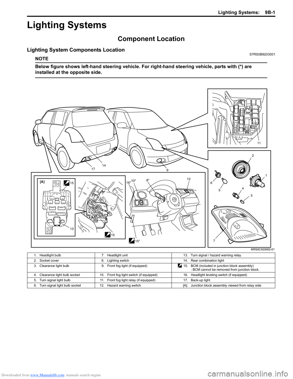
Lighting System Components LocationS7RS0B9203001
NOTE
Below figure shows left-hand steering vehicle. For right-hand steering vehicle, parts with (*) are
installed at the opposite side.
2
1
3
4
6
14
5
7
11
9
15
[A]
1515*
10*
8* 12
13
16*
17
I6RS0C920002-01
1. Headlight bulb 7. Headlight unit 13. Turn signal / hazard warning relay
2. Socket cover 8. Lighting switch 14. Rear combination light
3. Clearance light bulb 9. Front fog light (if equipped)15. BCM (included in junction block assembly)
: BCM cannot be removed from junction block.
4. Clearance light bulb socket 10. Front fog light switch (if equipped) 16. Headlight leveling switch (if equipped)
5. Turn signal light bulb 11. Front fog light relay (if equipped) 17. Back-up light
6. Turn signal light bulb socket 12. Hazard warning switch [A]: Junction block assembly viewed from relay side
Page 1284 of 1496

Downloaded from www.Manualslib.com manuals search engine 9B-2 Lighting Systems:
Interior Light System LocationS7RS0B9203002
Diagnostic Information and Procedures
Headlight Symptom DiagnosisS7RS0B9204001
Headlight Leveling System Symptom Diagnosis (If Equipped)S7RS0B9204002
13
2
4
I4RS0A920002-01
1. Dome light 3. Door switches (both sides)
2. Luggage compartment light (if equipped) 4. Rear end door switch (included in rear end door lock)
ConditionPossible cause Correction / Reference Item
Headlights do not light up Bulbs blown Replace bulbs.
Lighting or dimmer switch faulty Check headlight switch referring to “Headlight
Switch (in Lighting Switch) Inspection”.
Headlight R and L fuses blown Replace fuse and check for short circuit.
Wiring or grounding faulty Repair circuit.
Only one headlight does
not light up Bulb blown
Replace bulb.
Headlight R or L fuse blown Replace fuse and check for short circuit.
Wiring or grounding faulty Repair circuit.
Only one beam (“Hi” or
“Lo”) does not light Bulb blown
Replace bulb.
Lighting or dimmer switch faulty Check headlight switch referring to “Headlight
Switch (in Lighting Switch) Inspection”.
Wiring or grounding faulty Repair circuit.
ConditionPossible cause Correction / Reference Item
Optical axes of both
headlights do not change Circuit fuse blown
Replace fuse and check for short circuit.
Headlight leveling switch faulty Check headlight leveling switch referring to
“Headlight Leveling Switch Inspection (If
Equipped)”.
Supply voltage too low Check charging system referring to “Generator
Test (Undercharged Battery Check) in Section
1J”.
Wiring or grounding faulty Repair circuit.
Optical axis of only one
headlight does not
change Circuit fuse blown
Replace fuse and check for short circuit.
Headlight leveling actuator faulty Check actuator referring to “Headlight Leveling
Actuator Inspection (If Equipped)”.
Headlight housing deformed Replace headlight housing.
Wiring or grounding faulty Repair circuit.
Page 1285 of 1496
Downloaded from www.Manualslib.com manuals search engine Lighting Systems: 9B-3
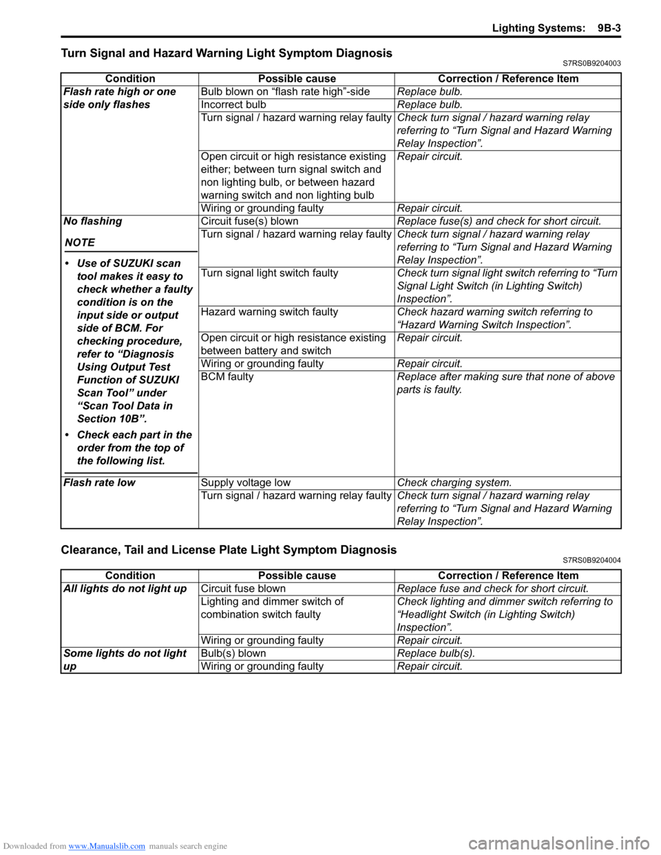
Turn Signal and Hazard Warning Light Symptom DiagnosisS7RS0B9204003
Clearance, Tail and License Plate Light Symptom DiagnosisS7RS0B9204004
ConditionPossible cause Correction / Reference Item
Flash rate high or one
side only flashes Bulb blown on “flash rate high”-side
Replace bulb.
Incorrect bulb Replace bulb.
Turn signal / hazard warning relay faulty Check turn signal / hazard warning relay
referring to “Turn Signal and Hazard Warning
Relay Inspection”.
Open circuit or high resistance existing
either; between turn signal switch and
non lighting bulb, or between hazard
warning switch and non lighting bulb Repair circuit.
Wiring or grounding faulty Repair circuit.
No flashing
NOTE
• Use of SUZUKI scan tool makes it easy to
check whether a faulty
condition is on the
input side or output
side of BCM. For
checking procedure,
refer to “Diagnosis
Using Output Test
Function of SUZUKI
Scan Tool” under
“Scan Tool Data in
Section 10B”.
• Check each part in the order from the top of
the following list.
Circuit fuse(s) blown Replace fuse(s) and check for short circuit.
Turn signal / hazard warning relay faulty Check turn signal / hazard warning relay
referring to “Turn Signal and Hazard Warning
Relay Inspection”.
Turn signal light switch faulty Check turn signal light switch referring to “Turn
Signal Light Switch (in Lighting Switch)
Inspection”.
Hazard warning switch faulty Check hazard warning switch referring to
“Hazard Warning Switch Inspection”.
Open circuit or high resistance existing
between battery and switch Repair circuit.
Wiring or grounding faulty Repair circuit.
BCM faulty Replace after making sure that none of above
parts is faulty.
Flash rate low Supply voltage low Check charging system.
Turn signal / hazard warning relay faulty Check turn signal / hazard warning relay
referring to “Turn Signal and Hazard Warning
Relay Inspection”.
ConditionPossible cause Correction / Reference Item
All lights do not light up Circuit fuse blown Replace fuse and check for short circuit.
Lighting and dimmer switch of
combination switch faulty Check lighting and dimmer switch referring to
“Headlight Switch (in Lighting Switch)
Inspection”.
Wiring or grounding faulty Repair circuit.
Some lights do not light
up Bulb(s) blown
Replace bulb(s).
Wiring or grounding faulty Repair circuit.
Page 1286 of 1496
Downloaded from www.Manualslib.com manuals search engine 9B-4 Lighting Systems:
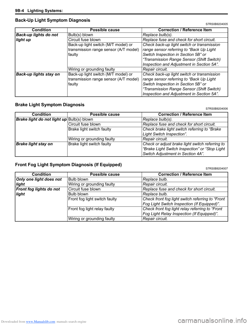
Back-Up Light Symptom DiagnosisS7RS0B9204005
Brake Light Symptom DiagnosisS7RS0B9204006
Front Fog Light Symptom Diagnosis (If Equipped)S7RS0B9204007
ConditionPossible cause Correction / Reference Item
Back-up lights do not
light up Bulb(s) blown
Replace bulb(s).
Circuit fuse blown Replace fuse and check for short circuit.
Back-up light switch (M/T model) or
transmission range sensor (A/T model)
faulty Check back-up light switch or transmission
range sensor referring to “Back Up Light
Switch Inspection in Section 5B” or
“Transmission Range Sensor (Shift Switch)
Inspection and Adjustment in Section 5A”.
Wiring or grounding faulty Repair circuit.
Back-up lights stay on Back-up light switch (M/T model) or
transmission range sensor (A/T model)
faulty Check back-up light switch or transmission
range sensor referring to “Back Up Light
Switch Inspection in Section 5B” or
“Transmission Range Sensor (Shift Switch)
Inspection and Adjustment in Section 5A”.
Condition
Possible cause Correction / Reference Item
Brake light do not light up Bulb(s) blown Replace bulb(s).
Circuit fuse blown Replace fuse and check for short circuit.
Brake light switch faulty Check brake light switch referring to “Brake
Light Switch Inspection”.
Wiring or grounding faulty Repair circuit.
Brake light stay on Brake light switch faulty Check or adjust brake light switch referring to
“Brake Light Switch Inspection” or “Stop Light
Switch Adjustment in Section 4A”.
ConditionPossible cause Correction / Reference Item
Only one light does not
light Bulb blown
Replace bulb.
Wiring or grounding faulty Repair circuit.
Front fog lights do not
light Circuit fuse blown
Replace fuse and check for short circuit.
Bulb blown Replace bulb.
Front fog light switch faulty Check front fog light switch referring to “Front
Fog Light Switch Inspection (If Equipped)”.
Front fog light relay faulty Check front fog light relay referring to “Front
Fog Light Relay Inspection (If Equipped)”.
Wiring or grounding faulty Repair circuit.
Page 1287 of 1496
Downloaded from www.Manualslib.com manuals search engine Lighting Systems: 9B-5
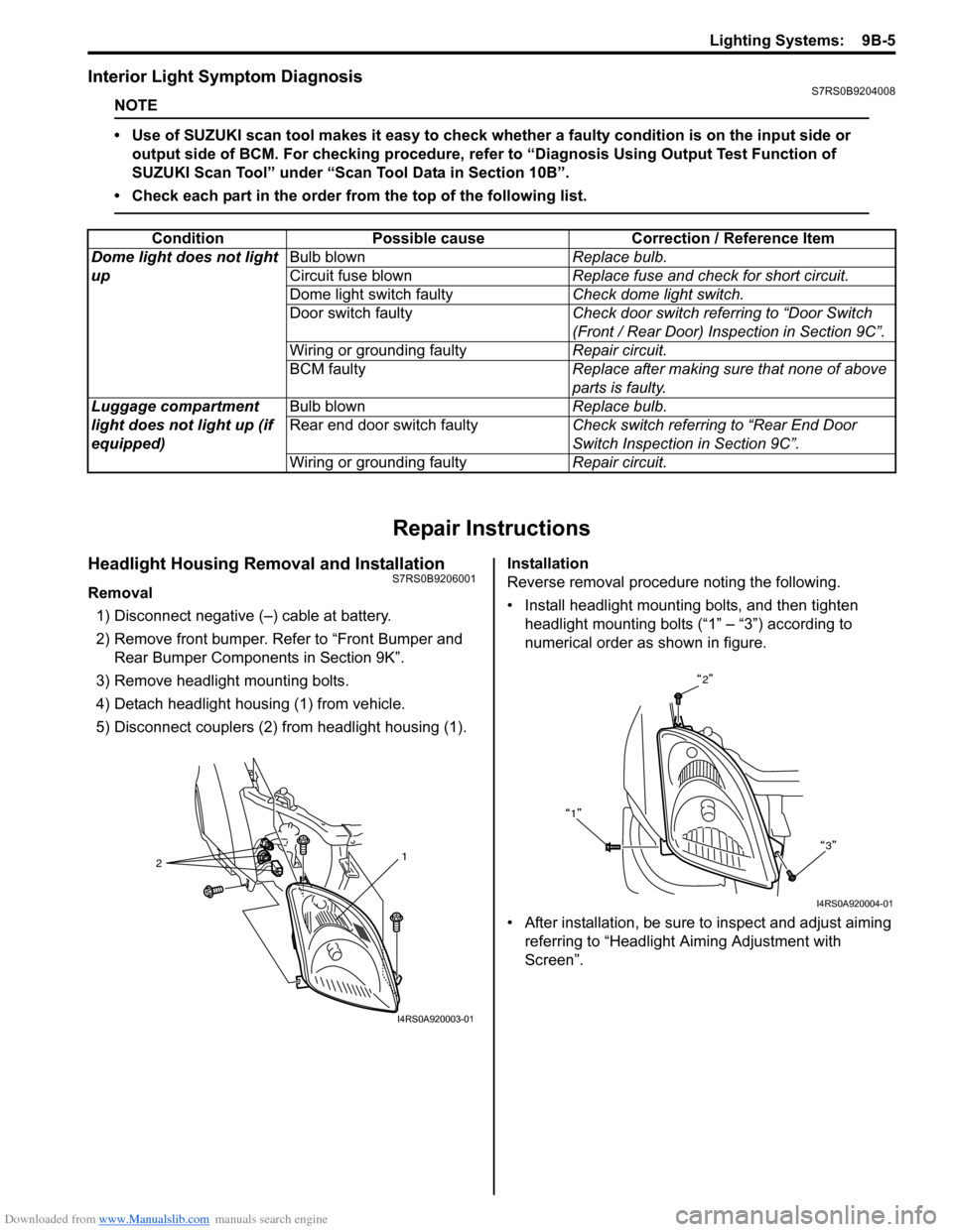
Interior Light Symptom DiagnosisS7RS0B9204008
NOTE
• Use of SUZUKI scan tool makes it easy to check whether a faulty condition is on the input side or
output side of BCM. For checking procedure, re fer to “Diagnosis Using Output Test Function of
SUZUKI Scan Tool” under “Scan Tool Data in Section 10B”.
• Check each part in the order from the top of the following list.
Repair Instructions
Headlight Housing Removal and InstallationS7RS0B9206001
Removal 1) Disconnect negative (–) cable at battery.
2) Remove front bumper. Refer to “Front Bumper and Rear Bumper Componen ts in Section 9K”.
3) Remove headlight mounting bolts.
4) Detach headlight housing (1) from vehicle.
5) Disconnect couplers (2) from headlight housing (1). Installation
Reverse removal procedure noting the following.
• Install headlight mounting bolts, and then tighten
headlight mounting bolts (“1” – “3”) according to
numerical order as shown in figure.
• After installation, be sure to inspect and adjust aiming referring to “Headlight Aiming Adjustment with
Screen”.
Condition Possible cause Correction / Reference Item
Dome light does not light
up Bulb blown
Replace bulb.
Circuit fuse blown Replace fuse and check for short circuit.
Dome light switch faulty Check dome light switch.
Door switch faulty Check door switch referring to “Door Switch
(Front / Rear Door) Inspection in Section 9C”.
Wiring or grounding faulty Repair circuit.
BCM faulty Replace after making sure that none of above
parts is faulty.
Luggage compartment
light does not light up (if
equipped) Bulb blown
Replace bulb.
Rear end door switch faulty Check switch referring to “Rear End Door
Switch Inspection in Section 9C”.
Wiring or grounding faulty Repair circuit.
2 1
I4RS0A920003-01
2
1 3
I4RS0A920004-01
Page 1288 of 1496
Downloaded from www.Manualslib.com manuals search engine 9B-6 Lighting Systems:
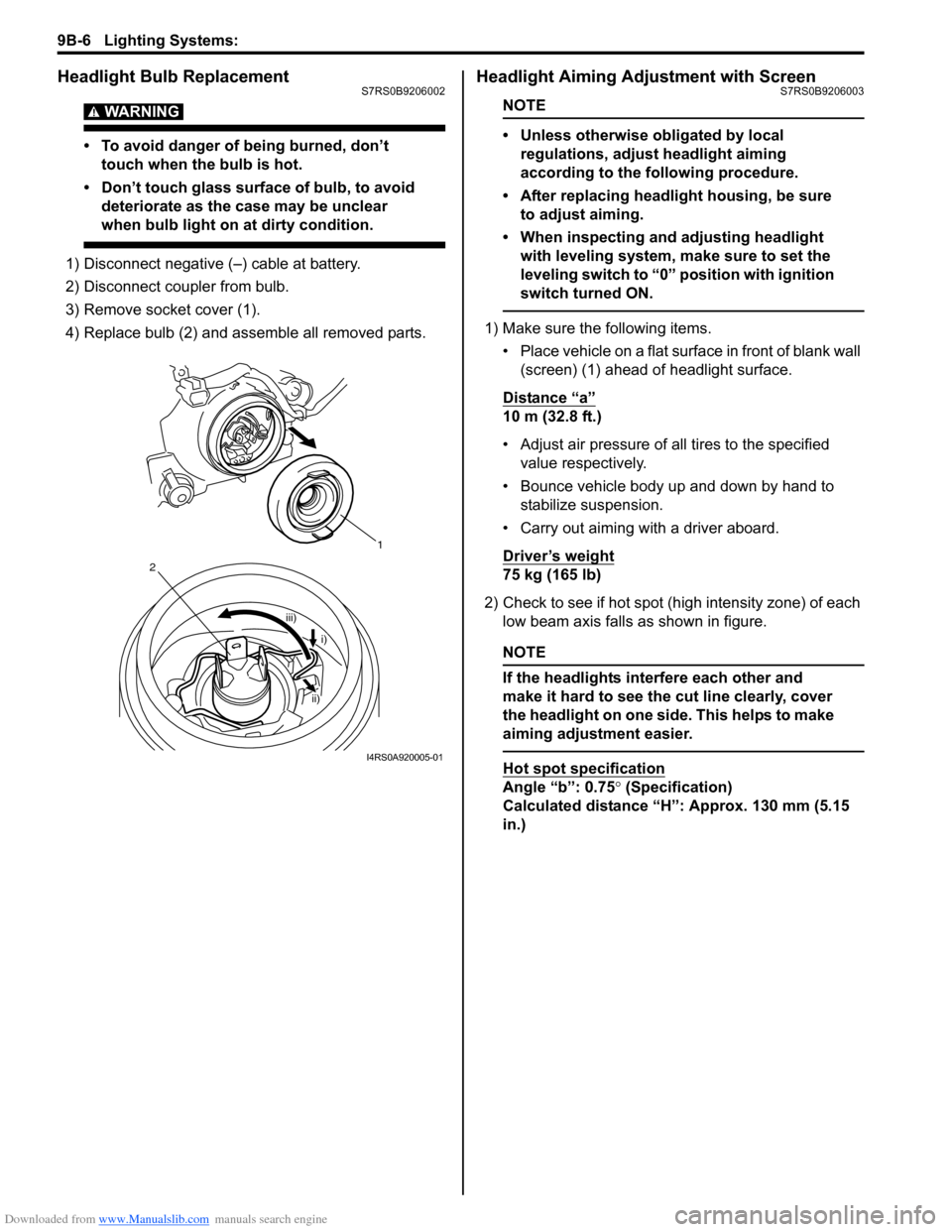
Headlight Bulb ReplacementS7RS0B9206002
WARNING!
• To avoid danger of being burned, don’t touch when the bulb is hot.
• Don’t touch glass surface of bulb, to avoid deteriorate as the case may be unclear
when bulb light on at dirty condition.
1) Disconnect negative (–) cable at battery.
2) Disconnect coupler from bulb.
3) Remove socket cover (1).
4) Replace bulb (2) and assemble all removed parts.
Headlight Aiming Adjustment with ScreenS7RS0B9206003
NOTE
• Unless otherwise obligated by local regulations, adjust headlight aiming
according to the following procedure.
• After replacing headlight housing, be sure to adjust aiming.
• When inspecting and adjusting headlight with leveling system, make sure to set the
leveling switch to “0 ” position with ignition
switch turned ON.
1) Make sure the following items.
• Place vehicle on a flat surface in front of blank wall (screen) (1) ahead of headlight surface.
Distance “a”
10 m (32.8 ft.)
• Adjust air pressure of all tires to the specified value respectively.
• Bounce vehicle body up and down by hand to stabilize suspension.
• Carry out aiming with a driver aboard.
Driver’s weight
75 kg (165 lb)
2) Check to see if hot spot (high intensity zone) of each low beam axis falls as shown in figure.
NOTE
If the headlights interfere each other and
make it hard to see the cut line clearly, cover
the headlight on one side. This helps to make
aiming adjustment easier.
Hot spot specification
Angle “b”: 0.75 ° (Specification)
Calculated distance “H”: Approx. 130 mm (5.15
in.)
1
iii)
2
i)
ii)
I4RS0A920005-01
Page 1290 of 1496
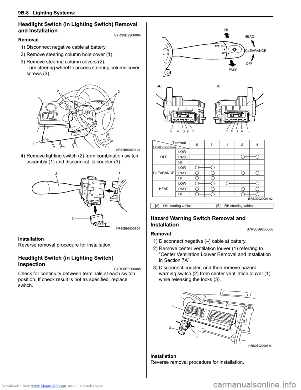
Downloaded from www.Manualslib.com manuals search engine 9B-8 Lighting Systems:
Headlight Switch (in Lighting Switch) Removal
and Installation
S7RS0B9206004
Removal1) Disconnect negative cable at battery.
2) Remove steering column hole cover (1).
3) Remove steering column covers (2). Turn steering wheel to acce ss steering column cover
screws (3).
4) Remove lighting switch (2 ) from combination switch
assembly (1) and disconnect its coupler (3).
Installation
Reverse removal procedure for installation.
Headlight Switch (in Lighting Switch)
Inspection
S7RS0B9206005
Check for continuity between terminals at each switch
position. If check result is not as specified, replace
switch.
Hazard Warning Switch Removal and
Installation
S7RS0B9206006
Removal 1) Disconnect negative (–) cable at battery.
2) Remove center ventilation louver (1) referring to
“Center Ventilation Louver Removal and Installation
in Section 7A”.
3) Disconnect coupler, and then remove hazard warning switch (2) from center ventilation louver (1)
while releasing the locks (3).
Installation
Reverse removal procedure for installation.
1
32
I4RS0B920004-02
1
2
3
I4RS0B920005-01
[A]: LH steering vehicle [B]: RH steering vehicle
Terminal
Shaft condition
OFF 5
3124
LOW
PASS
HI
LOW
PASS
HI LOW
PASS
HI
CLEARANCE
HEAD
HEADCLEARANCE
OFF
HI
PA S S
54321
54321
[A][B]
I5RS0D920004-02
1
2 3
I4RS0B920007-01