0b -10 SUZUKI SWIFT 2007 2.G Service Manual Online
[x] Cancel search | Manufacturer: SUZUKI, Model Year: 2007, Model line: SWIFT, Model: SUZUKI SWIFT 2007 2.GPages: 1496, PDF Size: 34.44 MB
Page 918 of 1496
Downloaded from www.Manualslib.com manuals search engine 6C-36 Power Assisted Steering System:
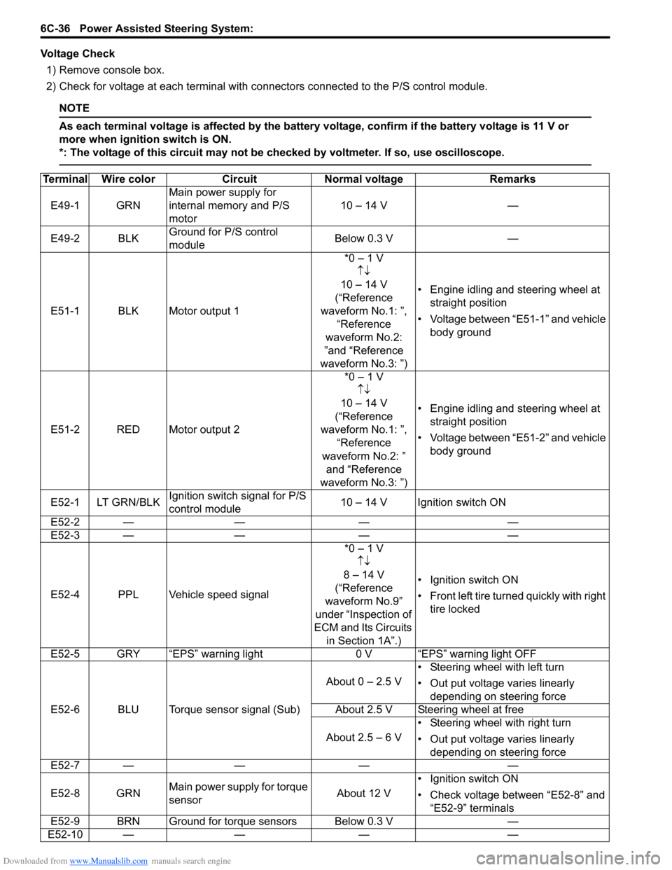
Voltage Check1) Remove console box.
2) Check for voltage at each terminal with co nnectors connected to the P/S control module.
NOTE
As each terminal voltage is affected by the battery voltage, confirm if the battery voltage is 11 V or
more when ignition switch is ON.
*: The voltage of this circuit may not be checked by voltmeter. If so, use oscilloscope.
Terminal Wire colorCircuit Normal voltage Remarks
E49-1 GRN Main power supply for
internal memory and P/S
motor 10 – 14 V
—
E49-2 BLK Ground for P/S control
module Below 0.3 V
—
E51-1 BLK Motor output 1 *0 – 1 V
↑↓
10 – 14 V
(“Reference
waveform No.1: ”, “Reference
waveform No.2:
”and “Reference
waveform No.3: ”) • Engine idling and steering wheel at
straight position
• Voltage between “E51-1” and vehicle body ground
E51-2 RED Motor output 2 *0 – 1 V
↑↓
10 – 14 V
(“Reference
waveform No.1: ”, “Reference
waveform No.2: ” and “Reference
waveform No.3: ”) • Engine idling and steering wheel at
straight position
• Voltage between “E51-2” and vehicle body ground
E52-1 LT GRN/BLK Ignition switch signal for P/S
control module 10 – 14 V Ignition switch ON
E52-2 — —— —
E52-3 — —— —
E52-4 PPL Vehicle speed signal *0 – 1 V
↑↓
8 – 14 V
(“Reference
waveform No.9”
under “Inspection of
ECM and Its Circuits in Section 1A”.) • Ignition switch ON
•Front left tire tu
rned quickly with right
tire locked
E52-5 GRY “EPS” warning light 0 V “EPS” warning light OFF
E52-6 BLU Torque sensor signal (Sub) About 0 – 2.5 V
• Steering wheel with left turn
• Out put voltage varies linearly
depending on steering force
About 2.5 V Steering wheel at free
About 2.5 – 6 V • Steering wheel with right turn
• Out put voltage varies linearly
depending on steering force
E52-7 — —— —
E52-8 GRN Main power supply for torque
sensor About 12 V• Ignition switch ON
• Check voltage between “E52-8” and
“E52-9” terminals
E52-9 BRN Ground for torque sensors Below 0.3 V —
E52-10 — —— —
Page 933 of 1496

Downloaded from www.Manualslib.com manuals search engine Table of Contents 7- i
7
Section 7
CONTENTS
HVAC
Precautions ................................................. 7-1
Precautions............................................................. 7-1
Precautions on HVAC ........................................... 7-1
Heater and Ventilation.... ......................... 7A-1
General Description ............................................. 7A-1
Heater and Ventilation Construction ................... 7A-1
Schematic and Routing Diagram ........................ 7A-2 Heater and Ventilation Wiring Circuit Diagram .... 7A-2
Diagnostic Information and Procedures ............ 7A-3 Heater and Ventilation Symptom Diagnosis........ 7A-3
Repair Instructions .............................................. 7A-4 HVAC Unit Components ..................................... 7A-4
HVAC Unit Removal and Installation .................. 7A-4
Blower Motor Removal and Installation............... 7A-4
Blower Motor Inspection ..................................... 7A-4
Blower Motor Resistor Removal and Installation ......................................................... 7A-5
Blower Motor Resistor Inspection ....................... 7A-5
Blower Motor Relay Inspection ........................... 7A-6
HVAC Control Unit Components ......................... 7A-6
HVAC Control Unit Remova l and Installation ...... 7A-7
Blower Speed Selector In spection ...................... 7A-9
Air Intake Selector Inspec tion ............................. 7A-9
Air Intake Control Actuator Removal and Installation ......................................................... 7A-9
Air Intake Control Actuator Inspection .............. 7A-10
Center Ventilation Louver Removal and Installation ....................................................... 7A-10
Side Ventilation Louver Removal and Installation ....................................................... 7A-11
HVAC Air Filter Removal and Installation (If Equipped)........................................................ 7A-12
HVAC Air Filter Inspection (If Equipped) ........... 7A-12
Air Conditioning System... ...................... 7B-1
Manual Type ............................................................ 7B-1
Precautions........................................................... 7B-1A/C System Caution ............................................ 7B-1
Precautions on Servicing A/C System ................ 7B-1
General Description ............................................. 7B-3 Refrigerant Type Identifica tion ............................ 7B-3
Sub-Cool A/C System Description ...................... 7B-4
A/C Operation Description .................................. 7B-4 Schematic and Routing Diagram ........................7B-5
Major Components of A/C System ...................... 7B-5
A/C System Wiring Diagram ............................... 7B-6
Diagnostic Information and Procedures ............7B-7 A/C System Symptom Diagnosis ........................ 7B-7
Abnormal Noise Sympto m Diagnosis of A/C
System .............................................................. 7B-9
A/C System Performance Inspection ................ 7B-10
A/C System Inspection at ECM ......................... 7B-15
Repair Instructions ........... .................................7B-16
Operation Procedure for Re frigerant Charge .... 7B-16
Condenser Assembly On-Vehicle Inspection .... 7B-21
Condenser Assembly Removal and Installation ....................................................... 7B-21
Receiver/Dryer Removal and Installation .......... 7B-22
HVAC Unit Components ................................... 7B-23
HVAC Unit Removal and In stallation ................ 7B-24
Evaporator Inspection ....................................... 7B-24
Evaporator Thermistor (Evaporator Temperature Sensor) Removal and
Installation ....................................................... 7B-25
Evaporator Thermistor (Evaporator Temperature Sensor) Inspec tion..................... 7B-25
Expansion Valve Removal and Installation ....... 7B-26
Expansion Valve Inspection .............................. 7B-26
A/C Refrigerant Pressure Sensor and Its Circuit Inspection............................................. 7B-26
A/C Refrigerant Pressu re Sensor Removal
and Installation ................................................ 7B-26
A/C Switch Inspection ....................................... 7B-27
Compressor Relay Inspection ........................... 7B-27
Compressor Drive Belt Inspection and Adjustment ...................................................... 7B-27
Compressor Drive Belt Removal and Installation ....................................................... 7B-28
Compressor Assembly Removal and Installation ....................................................... 7B-28
Compressor Assembly Components................. 7B-29
Magnet Clutch Inspection.................................. 7B-29
Magnet Clutch Removal and Installation........... 7B-29
Relief Valve Inspection...................................... 7B-31
Relief Valve Removal and Installation............... 7B-32
Specifications .................... .................................7B-32
Tightening Torque Specifications ...................... 7B-32
Special Tools and Equipmen t ...........................7B-33
Page 938 of 1496
Downloaded from www.Manualslib.com manuals search engine 7A-2 Heater and Ventilation:
Schematic and Routing Diagram
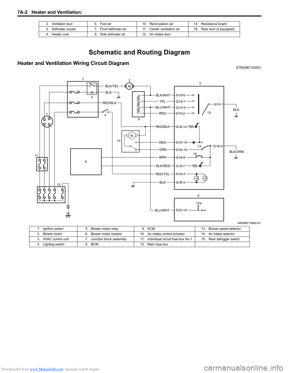
Heater and Ventilation Wiring Circuit DiagramS7RS0B7102001
2. Ventilator duct 6. Foot air 10. Recirculation air 14. Resistance board
3. Defroster nozzle 7. Front defroster air 11. Center ventilation air 15. Rear duct (if equipped)
4. Heater core 8. Side defroster air 12. Air intake door
BLK
RED/BLK
3
5
7
BLK
2
M
12V
BLU/WHTE23-19
G18-3
G18-4
G18-7
G18-8
G18-10
G18-13
G19-2
G19-3
G19-7
G19-6
G19-1
G18-9
G18-14
BLK/WHT
YEL
BLU/WHT
RED
RED/BLK
RED
GRN
BRN
BLK/RED
RED/YEL
BLK
BLK/YEL
BLK/ORN
4
6
10
8
9
M1
12
11 13
14
15
I4RS0B710002-01
1. Ignition switch 5. Blower motor relay 9. ECM 13. Blower speed selector
2. Blower motor 6. Blower motor resistor 10. Air intake control actuator 14. Air intake selector
3. HVAC control unit 7. Junction block assembly 11. Ind ividual circuit fuse box No.1 15. Rear defogger switch
4. Lighting switch 8. BCM 12. Main fuse box
Page 946 of 1496
Downloaded from www.Manualslib.com manuals search engine 7A-10 Heater and Ventilation:
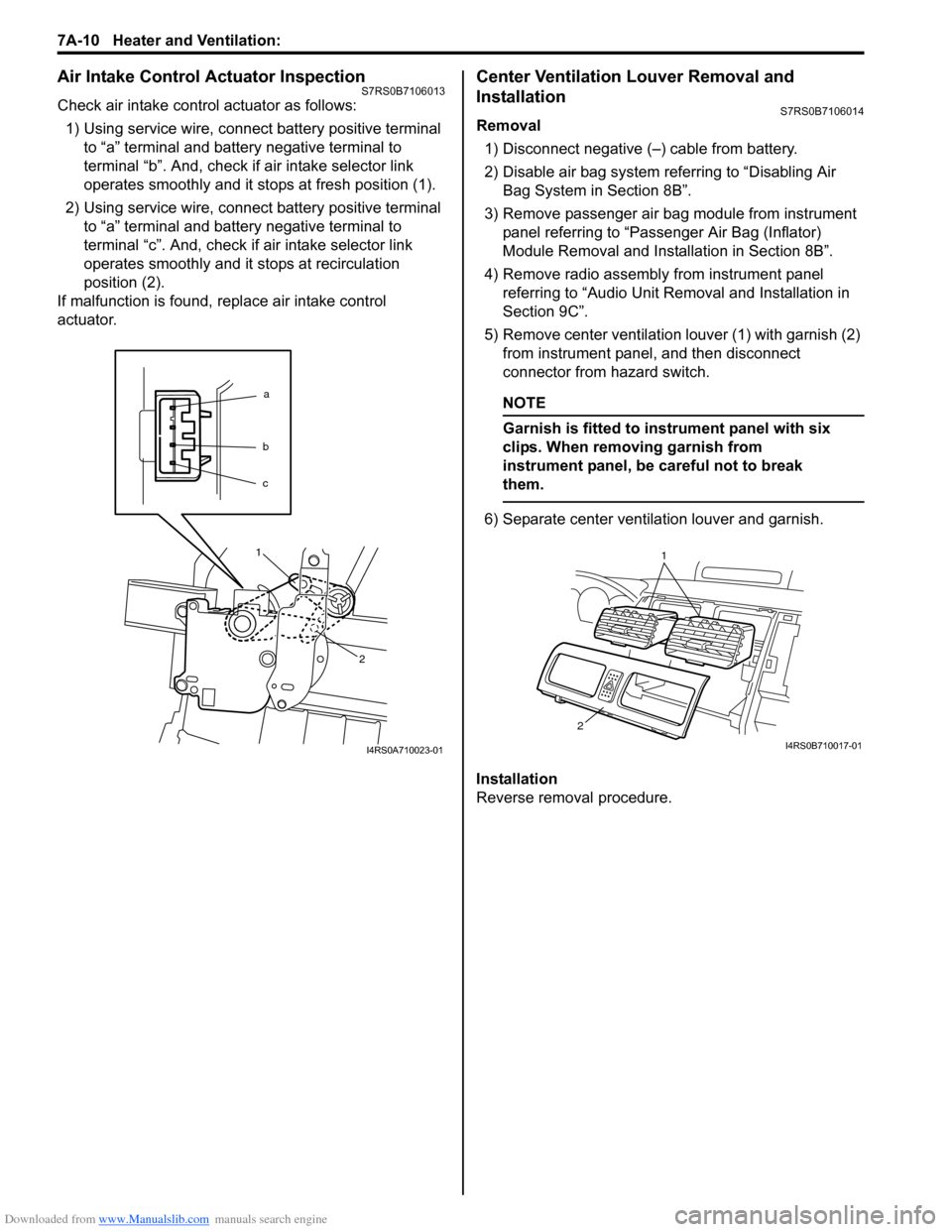
Air Intake Control Actuator InspectionS7RS0B7106013
Check air intake control actuator as follows:1) Using service wire, connect battery positive terminal to “a” terminal and battery negative terminal to
terminal “b”. And, check if air intake selector link
operates smoothly and it st ops at fresh position (1).
2) Using service wire, connect battery positive terminal to “a” terminal and battery negative terminal to
terminal “c”. And, check if air intake selector link
operates smoothly and it stops at recirculation
position (2).
If malfunction is found, replace air intake control
actuator.
Center Ventilation Louver Removal and
Installation
S7RS0B7106014
Removal
1) Disconnect negative (–) cable from battery.
2) Disable air bag system referring to “Disabling Air Bag System in Section 8B”.
3) Remove passenger air bag module from instrument panel referring to “Passenger Air Bag (Inflator)
Module Removal and Installation in Section 8B”.
4) Remove radio assembly from instrument panel referring to “Audio Unit Re moval and Installation in
Section 9C”.
5) Remove center ventilation louver (1) with garnish (2) from instrument panel, and then disconnect
connector from hazard switch.
NOTE
Garnish is fitted to in strument panel with six
clips. When removing garnish from
instrument panel, be careful not to break
them.
6) Separate center ventilation louver and garnish.
Installation
Reverse removal procedure.
a
b
c
1
2
I4RS0A710023-01
1
2
I4RS0B710017-01
Page 954 of 1496
Downloaded from www.Manualslib.com manuals search engine 7B-6 Air Conditioning System: Manual Type
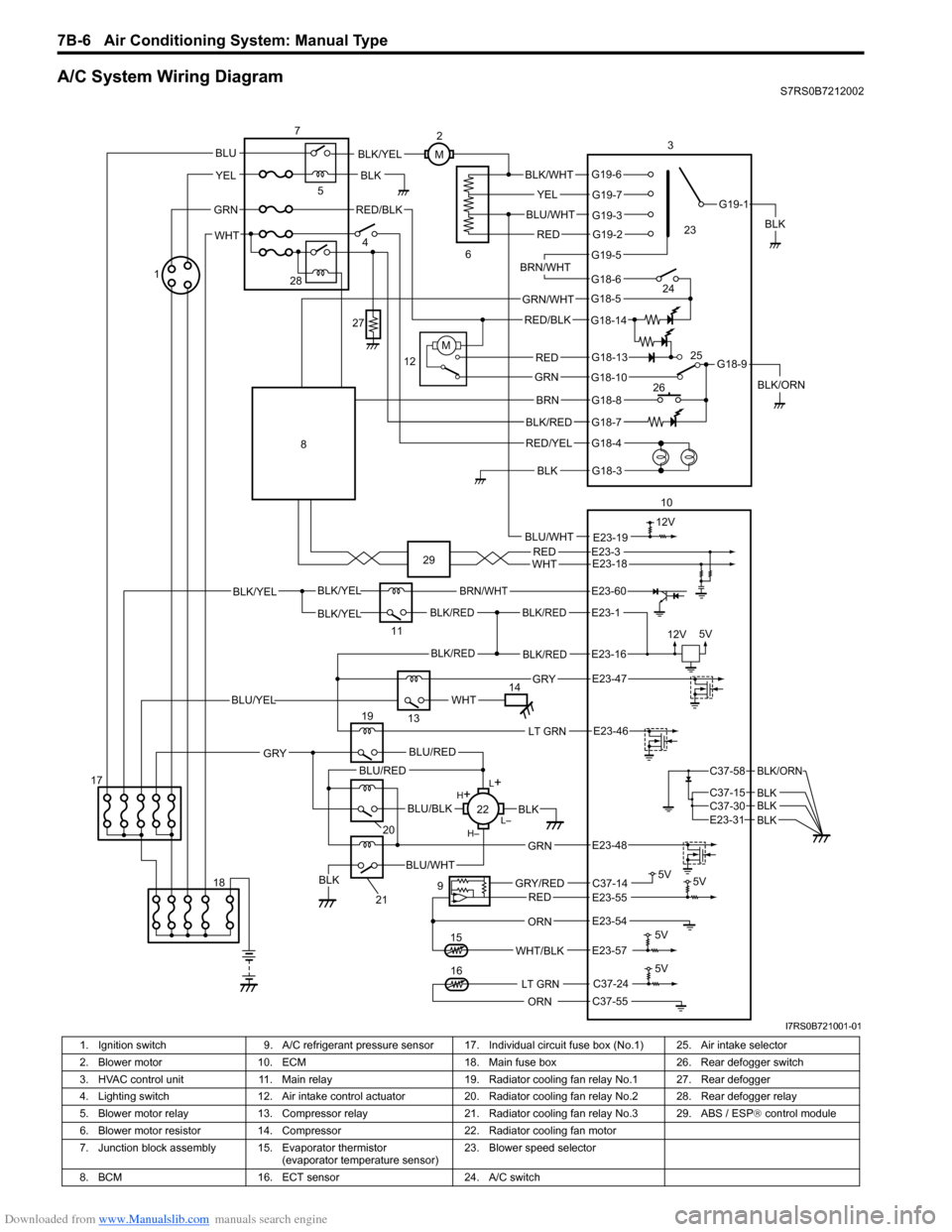
A/C System Wiring DiagramS7RS0B7212002
BLK/REDBLK/RED
BLK/YELBLK/YEL
BLK/YEL
BRN/WHT
12V5V
5V 5V
5V11
E23-1
E23-60
BLK/REDBLK/REDE23-16
E23-57WHT/BLK
9
13
E23-55C37-14GRY/REDRED
BLK
ORN
E23-47 GRY
WHTBLU/YEL
RED/BLK
14 3
1
15
5
7
BLK
2
M
12VBLU/WHTE23-19
C37-24
C37-55ORN
5V
LT GRN16
G18-3
G18-4
G18-7
G18-8
G18-10
G18-13
G18-5
G18-6
G19-5
G19-2
G19-3
G19-7
G19-6
G19-1
G18-9
G18-14
BLK/WHT
YEL
BLU/WHT
RED
BRN/WHT
GRN/WHT
RED/BLK
RED
GRN
BRN
BLK/RED
RED/YEL
BLK
BLK/YEL
BLK/ORN
4
6
12
10
M
E23-54
REDWHTE23-3E23-18
17 18
LT GRNE23-46
L+
L–
H–
H
+
BLU/RED
BLK
BLU/WHTBLK
BLU/BLK
20
GRN
GRY
E23-48
19
21
22
BLU/REDC37-58
C37-15 C37-30
BLK/ORN
BLKBLKE23-31 BLK
BLU
YEL
GRN
WHT
23
24
26 25
28
27
8
29
I7RS0B721001-01
1. Ignition switch
9. A/C refrigerant pressure sensor 17. I ndividual circuit fuse box (No.1) 25. Air intake selector
2. Blower motor 10. ECM 18. Main fuse box 26. Rear defogger switch
3. HVAC control unit 11. Main relay 19. Radiator cooling fan relay No.1 27. Rear defogger
4. Lighting switch 12. Air intake control actuator 20. Radiator cooling fan relay No.2 28. Rear defogger relay
5. Blower motor relay 13. Compressor relay 21. Radiator cooling fan relay No.3 29. ABS / ESP ® control module
6. Blower motor resistor 14. Compressor 22. Radiator cooling fan motor
7. Junction block assembly 15. Evaporator thermistor (evaporator temperature sensor)23. Blower speed selector
8. BCM 16. ECT sensor 24. A/C switch
Page 958 of 1496

Downloaded from www.Manualslib.com manuals search engine 7B-10 Air Conditioning System: Manual Type
Abnormal Noise from Tension Pulley
Abnormal Noise from A/C Evaporator
Abnormal Noise from Blower Motor
A/C System Performance InspectionS7RS0B7214003
1) Confirm that vehicle and environmental conditions are as follows.
• Vehicle is put indoors.
• Ambient temperature is within 25 – 35 °C (77 – 95
° F).
• Relative humidity is within 30 – 70%.
• There is no wind indoors.
• HVAC unit is normal.
• Blower motor is normal.
• There is no air leakage from air ducts.
• Condenser fins are clean.
• Air filter in HVAC unit is not clogged with dirt and
dust.
• Battery voltage is about 12 V.
• Radiator cooling fan operates normally.
2) Make sure that high pressure valve (1) and low pressure valve (2) of manifold gauge are firmly
closed.
3) Connect high pressure charging hose (3) to high pressure service valve (5) on vehicle and low
pressure charging hose (4) to low pressure service
valve (6).
4) Bleed the air in charging hoses (3) and (4) by loosening their nuts respectively utilizing the
refrigerant pressure. When a hissing sound is heard,
immediately tighten nut.
CAUTION!
Do not connect high and low pressure
charging hoses in reverse.
Condition Possible cause Correction / Reference Item
Clattering noise is heard
from pulley Worn or damaged bearing
Replace tension pulley.
Pulley cranks upon
contact Cracked or loose bracket
Replace or retighten bracket.
ConditionPossible cause Correction / Reference Item
Whistling sound is heard
from A/C evaporator Depending on the combination of the
interior / exterior temperatures, engine
rpm and refrigerant pressure, the
refrigerant flowing out of the expansion
valve may, under certain conditions,
make a whistling sound At times, slightly decrea
sing refrigerant volume
may stop this noise.
Inspect expansion valve and replace if faulty.
Condition Possible cause Correction / Reference Item
Blower motor emits a
chirping sound in
proportion to its speed of
rotation Worn or damaged motor brushes or
commutator
Replace blower motor.
Fluttering noise or large
droning noise is heard
from blower motor Leaves or other debris introduced from
fresh air inlet to blower motor
Remove debris and make sure that the screen
at fresh air inlet is intact.
53
2
1
4 6
I4RS0A720006-01
Page 986 of 1496
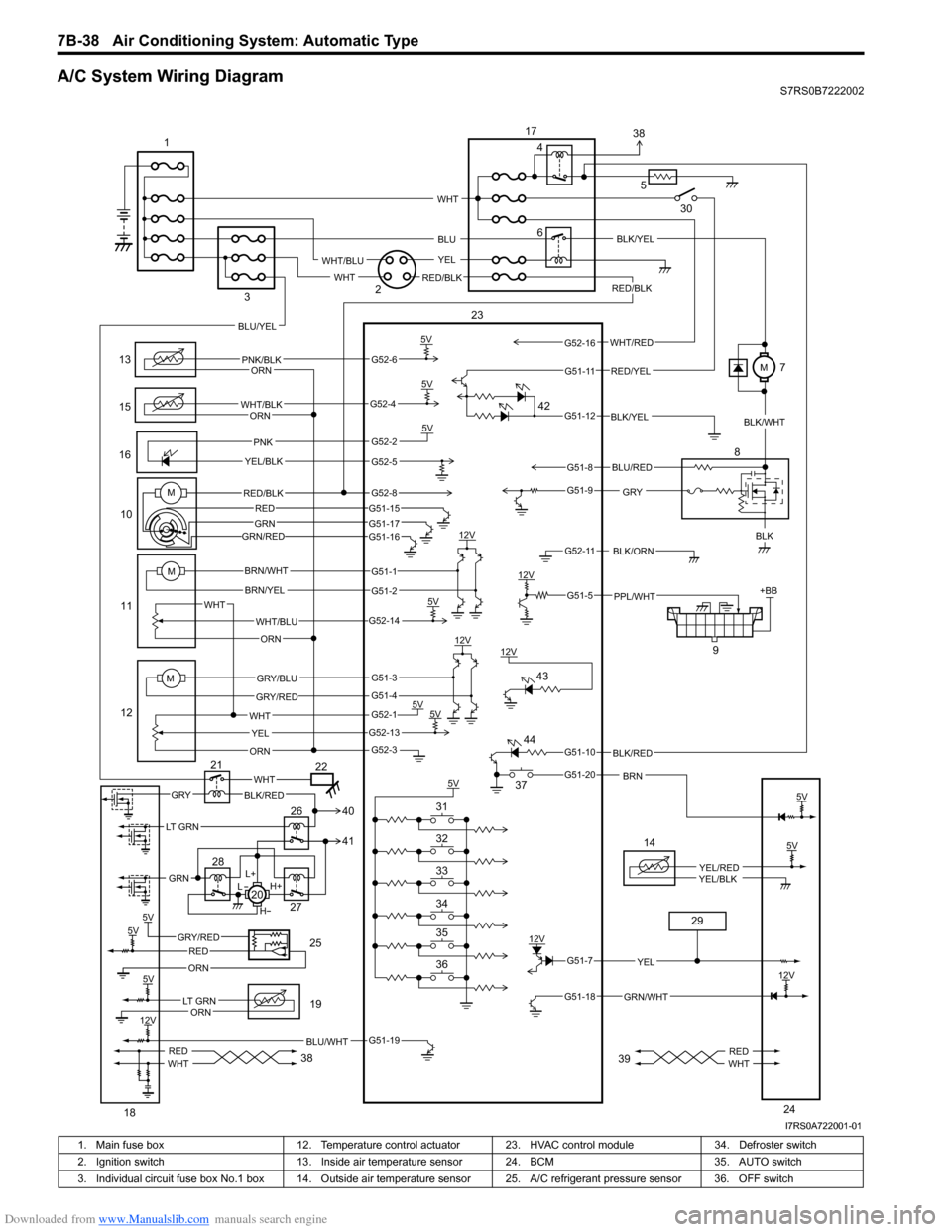
Downloaded from www.Manualslib.com manuals search engine 7B-38 Air Conditioning System: Automatic Type
A/C System Wiring DiagramS7RS0B7222002
6
13
15
1610
11
12 9
12V
5V
5V5V
12V
12V
5V 5V
5V +BB
PNK/BLK
WHT/BLK
GRYBLK
WHT/BLU
WHT YEL
ORN
BRN/WHT
BRN/YEL
GRY/BLU
GRY/RED
PNK
YEL/BLK
BLK/ORN
PPL/WHT
12V BLK/YEL
WHT
ORN
ORN
ORN
5V
BLK/RED
BRN
RED/BLK
5V
5VGRY/REDRED
ORN
BLU/WHT
14
YEL/REDYEL/BLK
GRN/WHT
12V
YEL
L+
H+
L
H
WHTGRYBLK/RED
REDWHTREDWHT
M
M
WHT/RED
5
BLU
YEL
WHT
WHT/BLU
RED/BLKWHT
RED/YEL
BLU/YEL
LT GRN
GRN
BLU/RED
G52-6
G52-4
G52-2
G52-5
G51-1
G51-2
G52-14
G51-3
G51-4
G52-1
G52-13
G52-3
G51-19
G51-7
G51-18
G51-10
G51-20
G51-5
G52-11
G51-9
G51-8
G51-12
G51-11
G52-16
5V
12V
5V
12V
LT GRNORN
5V
23
1
2
3 4
8
17
18 19
20
21
22
24
25
26
27
28
29
30
36 35 34 33 32 31 37
38 3938
41 40
42
43
44
MRED/BLK
GRN/RED
G52-8G51-15
G51-17G51-16
REDGRN
BLK/YEL
BLK/WHT
M7
I7RS0A722001-01
1. Main fuse box 12. Temperature control actuator 23. HVAC control module 34. Defroster switch
2. Ignition switch 13. Inside air temperature sensor 24. BCM 35. AUTO switch
3. Individual circuit fuse box No.1 box 14. Outside air temper ature sensor 25. A/C refrigerant pressure sensor 36. OFF switch
Page 1016 of 1496
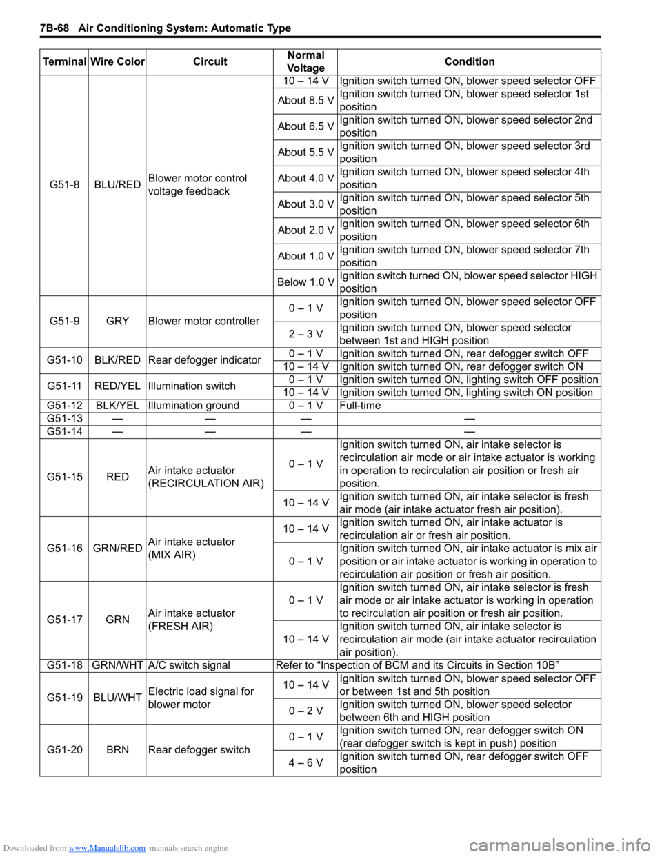
Downloaded from www.Manualslib.com manuals search engine 7B-68 Air Conditioning System: Automatic Type
G51-8 BLU/REDBlower motor control
voltage feedback 10 – 14 V Ignition switch turned ON, blower speed selector OFF
About 8.5 V Ignition switch turned ON, blower speed selector 1st
position
About 6.5 V Ignition switch turned ON, blower speed selector 2nd
position
About 5.5 V Ignition switch turned ON, blower speed selector 3rd
position
About 4.0 V Ignition switch turned ON, blower speed selector 4th
position
About 3.0 V Ignition switch turned ON, blower speed selector 5th
position
About 2.0 V Ignition switch turned ON, blower speed selector 6th
position
About 1.0 V Ignition switch turned ON, blower speed selector 7th
position
Below 1.0 V Ignition switch turned ON, blower speed selector HIGH
position
G51-9 GRY Blower motor controller 0 – 1 V
Ignition switch turned ON, blower speed selector OFF
position
2 – 3 V Ignition switch turned ON, blower speed selector
between 1st and HIGH position
G51-10 BLK/RED Rear defogger indicator 0 – 1 V Ignition switch turned ON, rear defogger switch OFF
10 – 14 V Ignition switch turned ON, rear defogger switch ON
G51-11 RED/YEL Illumination switch 0 – 1 V Ignition switch turned ON, lighting switch OFF position
10 – 14 V Ignition switch turned ON, lighting switch ON position
G51-12 BLK/YEL Illumination ground 0 – 1 V Full-time
G51-13 — — — —
G51-14 — — — —
G51-15 RED Air intake actuator
(RECIRCULATION AIR) 0 – 1 VIgnition switch turned ON, air intake selector is
recirculation air mode or air intake actuator is working
in operation to recirculation air position or fresh air
position.
10 – 14 V Ignition switch turned ON, ai
r intake selector is fresh
air mode (air intake actuator fresh air position).
G51-16 GRN/RED Air intake actuator
(MIX AIR) 10 – 14 V
Ignition switch turned ON, air intake actuator is
recirculation air or fresh air position.
0 – 1 V Ignition switch turned ON, air intake actuator is mix air
position or air intake actuator is working in operation to
recirculation air position or fresh air position.
G51-17 GRN Air intake actuator
(FRESH AIR) 0 – 1 V
Ignition switch turned ON, ai
r intake selector is fresh
air mode or air intake actuator is working in operation
to recirculation air position or fresh air position.
10 – 14 V Ignition switch turned ON, air intake selector is
recirculation air mode (air intake actuator recirculation
air position).
G51-18 GRN/WHT A/C switch signal Refer to “Inspe ction of BCM and its Circuits in Section 10B”
G51-19 BLU/WHT Electric load signal for
blower motor 10 – 14 V
Ignition switch turned ON, blower speed selector OFF
or between 1st and 5th position
0 – 2 V Ignition switch turned ON, blower speed selector
between 6th and HIGH position
G51-20 BRN Rear defogger switch 0 – 1 V
Ignition switch turned ON, rear defogger switch ON
(rear defogger switch is kept in push) position
4 – 6 V Ignition switch turned ON, rear defogger switch OFF
position
Terminal Wire Color Circuit
Normal
Vo l ta g e Condition
Page 1017 of 1496
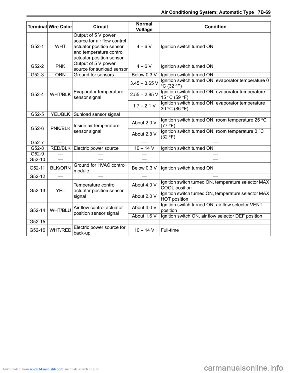
Downloaded from www.Manualslib.com manuals search engine Air Conditioning System: Automatic Type 7B-69
Terminal Wire Color CircuitNormal
Vo l ta g e Condition
G52-1 WHT Output of 5 V power
source for air flow control
actuator position sensor
and temperature control
actuator position sensor 4 – 6 V Ignition switch turned ON
G52-2 PNK Output of 5 V power
source for sunload sensor 4 – 6 V Ignition switch turned ON
G52-3 ORN Ground for sensors Below 0.3 V Ignition switch turned ON
G52-4 WHT/BLK Evaporator temperature
sensor signal 3.45 – 3.65 V
Ignition switch turned ON, evaporator temperature 0
°
C (32 °F)
2.55 – 2.85 V Ignition switch turned ON, evaporator temperature
15
°C (59 ° F)
1.7 – 2.1 V Ignition switch turned ON, evaporator temperature
30
°C (86 ° F)
G52-5 YEL/BLK Sunload sensor signal
G52-6 PNK/BLK Inside air temperature
sensor signal About 2.0 V
Ignition switch turned ON, room temperature 25
°C
(77 °F)
About 2.8 V Ignition switch turned ON, room temperature 0
°C
(32 °F)
G52-7 — — — —
G52-8 RED/BLK Electric power source 10 – 14 V Ignition switch turned ON
G52-9 — — — —
G52-10 — — — —
G52-11 BLK/ORN Ground for HVAC control
module Below 0.3 V Ignition
switch turned ON
G52-12 — — — —
G52-13 YEL Temperature control
actuator position sensor
signal About 4.0 V
Ignition switch turned ON, temperature selector MAX
COOL position
About 2.0 V Ignition switch turned ON, temperature selector MAX
HOT position
G52-14 WHT/BLU Air flow control actuator
position sensor signal About 4.0 V
Ignition switch turned ON
, air flow selector VENT
position
About 1.6 V Ignition switch ON, air flow selector DEF position
G52-15 — — — —
G52-16 WHT/RED Electric power source for
back-up 10 – 14 V Full-time
Page 1029 of 1496
Downloaded from www.Manualslib.com manuals search engine Table of Contents 8- i
8
Section 8
CONTENTS
Restraint
Precautions ................................................. 8-1
Precautions............................................................. 8-1
Precautions on Restraint ....................................... 8-1
Seat Belts .......... ............................... ........ 8A-1
Precautions........................................................... 8A-1
Precautions on Service a nd Diagnosis of Seat
Belt .................................................................... 8A-1
General Description ............................................. 8A-1 Seat Belt Construction ........................................ 8A-1
Diagnostic Information and Procedures ............ 8A-2 Repair and Inspection Required after Accident ............................................................ 8A-2
Repair Instructions .............................................. 8A-3 Front Seat Belt Components ............................... 8A-3
Front Seat Belt Removal and Installation ............ 8A-4
Front Seat Belt Inspection ................................... 8A-4
Rear Seat Belt Components ............................... 8A-6
Rear Seat Belt Removal and Installation ............ 8A-7
Rear Seat Belt Inspection ................................... 8A-7
Specifications ....................................................... 8A-7
Tightening Torque Specifications ........................ 8A-7
Air Bag System ............... ......................... 8B-1
Precautions........................................................... 8B-1
Precautions on Service and Diagnosis of Air Bag System....................................................... 8B-1
Precautions on Handling and Storage of Air Bag System Components . ................................ 8B-2
Precautions on Disposal of Air Bag and Seat
Belt Pretensioner .............................................. 8B-5
General Description ............................................. 8B-5 Air Bag System Construction .............................. 8B-5
Air Bag System Input / Output Table .................. 8B-6
Schematic and Routing Diagram ........................ 8B-7 Air Bag System Wiring Circuit Diagram .............. 8B-7
Component Locatio n ........................................... 8B-9
Air Bag System Components, Wiring and Connectors Location ......................................... 8B-9
Diagnostic Information and Procedures .......... 8B-10 Air Bag Diagnostic System Check .................... 8B-10
Air Bag Diagnostic System Check Flow ............ 8B-10
DTC Table ......................................................... 8B-11
DTC Check ....................................................... 8B-12 DTC Clearance ................................................. 8B-12
Scan Tool Data ................................................. 8B-13
“AIR BAG” Warning Right Comes ON Steady .. 8B-13
“AIR BAG” Warning Right Does Not Come
ON ................................................................... 8B-15
“AIR BAG” Warning Right Flashes .................... 8B-16
DTC B1013: SDM fault...................................... 8B-17
DTC B1014: “AIR BAG” Warning Right Circuit Failure ............................................................. 8B-17
DTC B1016: Power Source Voltage High ......... 8B-18
DTC B1017: Power Source Voltage Low .......... 8B-20
DTC B1021: Front Air Bag Module Deployed ... 8B-22
DTC B1024 / B1025: Side-Air Bag (Driver / Passenger) Deployed...................................... 8B-22
DTC B1026: Pretensioner Activated ................. 8B-23
DTC B1027: Reusable Number Exceeded ....... 8B-24
DTC B1031: Driver Air Bag Initiator Circuit
Resistance High .............................................. 8B-24
DTC B1032: Driver Air Bag Initiator Circuit
Resistance Low ............................................... 8B-29
DTC B1033: Driver Air Bag Initiator Circuit
Short to Ground............................................... 8B-34
DTC B1034: Driver Air Bag Initiator Circuit
Short to Power Circuit .... ................................. 8B-39
DTC B1041: Passenger Air Bag Initiator Circuit Resistance High ................................... 8B-44
DTC B1042: Passenger Air Bag Initiator Circuit Resistance Low.................................... 8B-47
DTC B1043: Passenger Air Bag Initiator Circuit Short to Ground ................................... 8B-50
DTC B1044: Passenger Air Bag Initiator Circuit Short to Power Circ uit .......................... 8B-53
DTC B1051 / B1055: Driver / Passenger Pretensioner Initiator Circuit Resistance
High ................................................................. 8B-56
DTC B1052 / B1056: Driver / Passenger Pretensioner Initiator Circu it Resistance Low .. 8B-58
DTC B1053 / B1057: Driver / Passenger Pretensioner Initiator Circuit Short to Ground .. 8B-60
DTC B1054 / B1058: Driver / Passenger Pretensioner Initiator Circuit Short to Power
Circuit .............................................................. 8B-62
DTC B1061 / B1065: Driver / Passenger Side- Air Bag Initiator Circuit Resistance High ......... 8B-64