Lock SUZUKI SWIFT 2007 2.G Service Manual Online
[x] Cancel search | Manufacturer: SUZUKI, Model Year: 2007, Model line: SWIFT, Model: SUZUKI SWIFT 2007 2.GPages: 1496, PDF Size: 34.44 MB
Page 390 of 1496
Downloaded from www.Manualslib.com manuals search engine 1G-15 Fuel System:
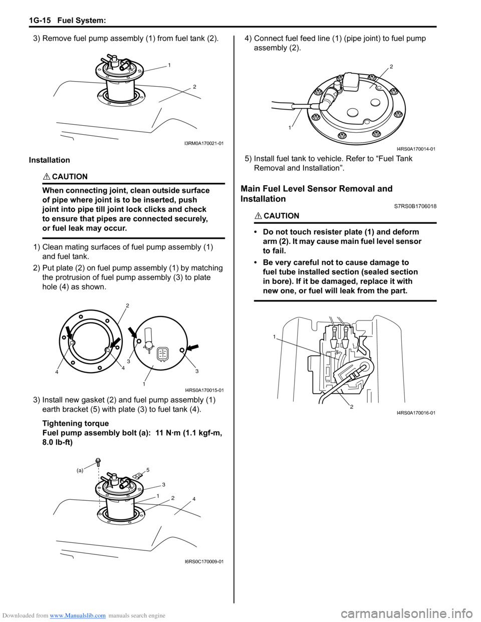
3) Remove fuel pump assembly (1) from fuel tank (2).
Installation
CAUTION!
When connecting joint, clean outside surface
of pipe where joint is to be inserted, push
joint into pipe till jo int lock clicks and check
to ensure that pipes are connected securely,
or fuel leak may occur.
1) Clean mating surfaces of fuel pump assembly (1) and fuel tank.
2) Put plate (2) on fuel pump assembly (1) by matching the protrusion of fuel pump assembly (3) to plate
hole (4) as shown.
3) Install new gasket (2) and fuel pump assembly (1) earth bracket (5) with plate (3) to fuel tank (4).
Tightening torque
Fuel pump assembly bolt (a): 11 N·m (1.1 kgf-m,
8.0 lb-ft) 4) Connect fuel feed line (1) (pipe joint) to fuel pump
assembly (2).
5) Install fuel tank to vehi cle. Refer to “Fuel Tank
Removal and Installation”.
Main Fuel Level Sensor Removal and
Installation
S7RS0B1706018
CAUTION!
• Do not touch resister plate (1) and deform arm (2). It may cause main fuel level sensor
to fail.
• Be very careful not to cause damage to fuel tube installed section (sealed section
in bore). If it be damaged, replace it with
new one, or fuel will leak from the part.
1
2
I3RM0A170021-01
3
1
3
2
44
I4RS0A170015-01
3
1 2
(a)
4
5
I6RS0C170009-01
2
1
I4RS0A170014-01
1
2I4RS0A170016-01
Page 394 of 1496
Downloaded from www.Manualslib.com manuals search engine 1H-2 Ignition System:
Schematic and Routing Diagram
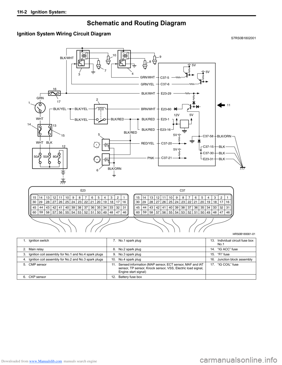
Ignition System Wiring Circuit DiagramS7RS0B1802001
E23-60
E23-29 12V 5V
5V
E23-1
E23-16
BLK/WHT
BLK/RED
BLK/RED BLK/RED
BLK/YELBLK/YEL
BLK/YEL
GRN
BLKWHT
WHT
BRN/WHT
BLK/ORN
BLK
BLK
C37-20
BLK/RED
PNK
5V
C37-21
BLK/WHT
7
3 4
1
12 5
6
2
11
8
9
10
GRN/YEL
GRN/WHT
C37-6
C37-5 5V
5V
RED/YEL
C37-58
C37-15
C37-30
E23
C37
34
1819
567
1011
17
20
47 46
495051
2122
52 16
25 9
24
14
29
55
57 54 53
59
60 58 2
262728
15
30
56 4832 31
34353637
40
42 39 38
44
45 43 41 331
1213
238
34
1819
567
1011
17
20
47 46
495051
2122
52 16
25 9
24
14
29
55
57 54 53
59
60 58 2
262728
15
30
56 4832 31
34353637
40
42 39 38
44
45 43 41 331
1213
238
13
14
15
16
17
50A50A80A
BLK/ORN
E23-31 BLK
I4RS0B180001-01
1. Ignition switch 7. No.1 spark plug 13. Individual circuit fuse box
No.1
2. Main relay 8. No.2 spark plug 14. “IG ACC” fuse
3. Ignition coil assembly for No.1 and No.4 spark plugs 9. No.3 spark plug 15. “FI” fuse
4. Ignition coil assembly for No.2 and No.3 spark plugs 10. No.4 spark plug 16. Junction block assembly
5. CMP sensor 11. Sensed information (MAP sensor, ECT sensor, MAF and IAT
sensor, TP sensor, Knock sensor, VSS, Electric load signal,
Engine start signal) 17. “IG COIL” fuse
6. CKP sensor 12. Battery fuse box
Page 395 of 1496
Downloaded from www.Manualslib.com manuals search engine Ignition System: 1H-3
Component Location
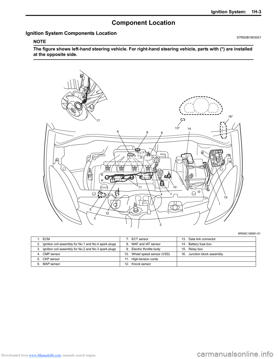
Ignition System Components LocationS7RS0B1803001
NOTE
The figure shows left-hand steering vehicle. For right-hand steering vehicle, parts with (*) are installed
at the opposite side.
16*
1
2
14
7
5 12 11
410
6
89
3 13*
15
17
I6RS0C180001-01
1. ECM 7. ECT sensor13. Data link connector
2. Ignition coil assembly for No.1 and No.4 spark plugs 8. MAF and IAT sensor 14. Battery fuse box
3. Ignition coil assembly for No.2 and No.3 spark plugs 9. Electric throttle body 15. Relay box
4. CMP sensor 10. Wheel speed sensor (VSS) 16. Junction block assembly
5. CKP sensor 11. High-tension cords
6. MAP sensor 12. Knock sensor
Page 408 of 1496
Downloaded from www.Manualslib.com manuals search engine 1I-7 Starting System:
Spring
Inspect brush springs for wear, damage or other
abnormal conditions. Replace if necessary.
Brush spring tension
Standard: 2.2 kg (4.85 lb)
Limit: 0.6 kg (1.33 lb)
Brush Holder
• Check movement of brush in brush holder. If brush movement within brush holder is sluggish, check
brush holder for distortion and sliding faces for
contamination.
Clean or correct as necessary.
• Check for continuity across insulated brush (positive side) and grounded brush (negative side).
If continuity exists, brus h holder is grounded due to
defective insulation and should be replaced.
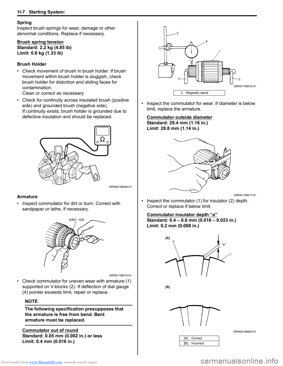
Armature
• Inspect commutator for dirt or burn. Correct with sandpaper or lathe, if necessary.
• Check commutator for uneven wear with armature (1) supported on V-blocks (2). If deflection of dial gauge
(4) pointer exceeds limit, repair or replace.
NOTE
The following specification presupposes that
the armature is free from bend. Bent
armature must be replaced.
Commutator out of round
Standard: 0.05 mm (0.002 in.) or less
Limit: 0.4 mm (0.016 in.) • Inspect the commutator for wear. If diameter is below
limit, replace the armature.
Commutator outside diameter
Standard: 29.4 mm (1.16 in.)
Limit: 28.8 mm (1.14 in.)
• Inspect the commutator (1) for insulator (2) depth. Correct or replace if below limit.
Commutator insulator depth “a”
Standard: 0.4 – 0.6 mm (0.016 – 0.023 in.)
Limit: 0.2 mm (0.008 in.)
I4RS0A190004-01
I2RH01190015-01
3. Magnetic stand
[A]: Correct
[B]: Incorrect
I2RH01190016-01
I2RH01190017-01
I3RH0A190005-01
Page 409 of 1496
Downloaded from www.Manualslib.com manuals search engine Starting System: 1I-8
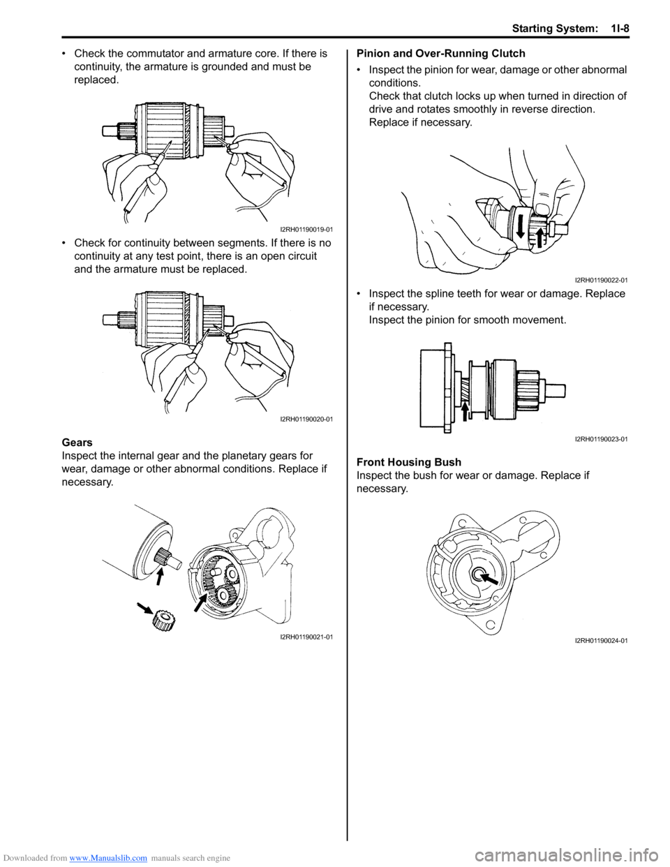
• Check the commutator and armature core. If there is
continuity, the armature is grounded and must be
replaced.
• Check for continuity between segments. If there is no continuity at any test point , there is an open circuit
and the armature must be replaced.
Gears
Inspect the internal gear and the planetary gears for
wear, damage or other abnorma l conditions. Replace if
necessary. Pinion and Over-Running Clutch
• Inspect the pinion for wear, damage or other abnormal
conditions.
Check that clutch locks up when turned in direction of
drive and rotates smoothly in reverse direction.
Replace if necessary.
• Inspect the spline teeth for wear or damage. Replace if necessary.
Inspect the pinion for smooth movement.
Front Housing Bush
Inspect the bush for wear or damage. Replace if
necessary.
I2RH01190019-01
I2RH01190020-01
I2RH01190021-01
I2RH01190022-01
I2RH01190023-01
I2RH01190024-01
Page 410 of 1496
Downloaded from www.Manualslib.com manuals search engine 1I-9 Starting System:
Specifications
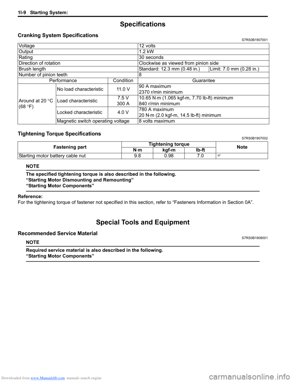
Cranking System SpecificationsS7RS0B1907001
Tightening Torque SpecificationsS7RS0B1907002
NOTE
The specified tightening torque is also described in the following.
“Starting Motor Dismounting and Remounting”
“Starting Motor Components”
Reference:
For the tightening torque of fastener not specified in this section, refer to “Fasteners Information in Section 0A”.
Special Tools and Equipment
Recommended Service MaterialS7RS0B1908001
NOTE
Required service material is also described in the following.
“Starting Motor Components”
Voltage 12 volts
Output 1.2 kW
Rating 30 seconds
Direction of rotation Clockwise as viewed from pinion side
Brush length Standard: 12.3 mm (0.48 in.) Limit: 7.0 mm (0.28 in.)
Number of pinion teeth 8
Performance Condition Guarantee
Around at 20 °C
(68 °F) No load characteristic 11.0 V
90 A maximum
2370 r/min minimum
Load characteristic 7.5 V
300 A 10.65 N
⋅m (1.065 kgf-m, 7.70 lb-ft) minimum
840 r/min minimum
Locked characteristic 4.0 V 780 A maximum
20 N
⋅m (2.0 kgf-m, 14.5 lb-ft) minimum
Magnetic switch operating voltage 8 volts maximum
Fastening part Tightening torque
Note
N ⋅mkgf-mlb-ft
Starting motor battery cable nut 9.8 0.98 7.0 �)
Page 418 of 1496
Downloaded from www.Manualslib.com manuals search engine 1J-8 Charging System:
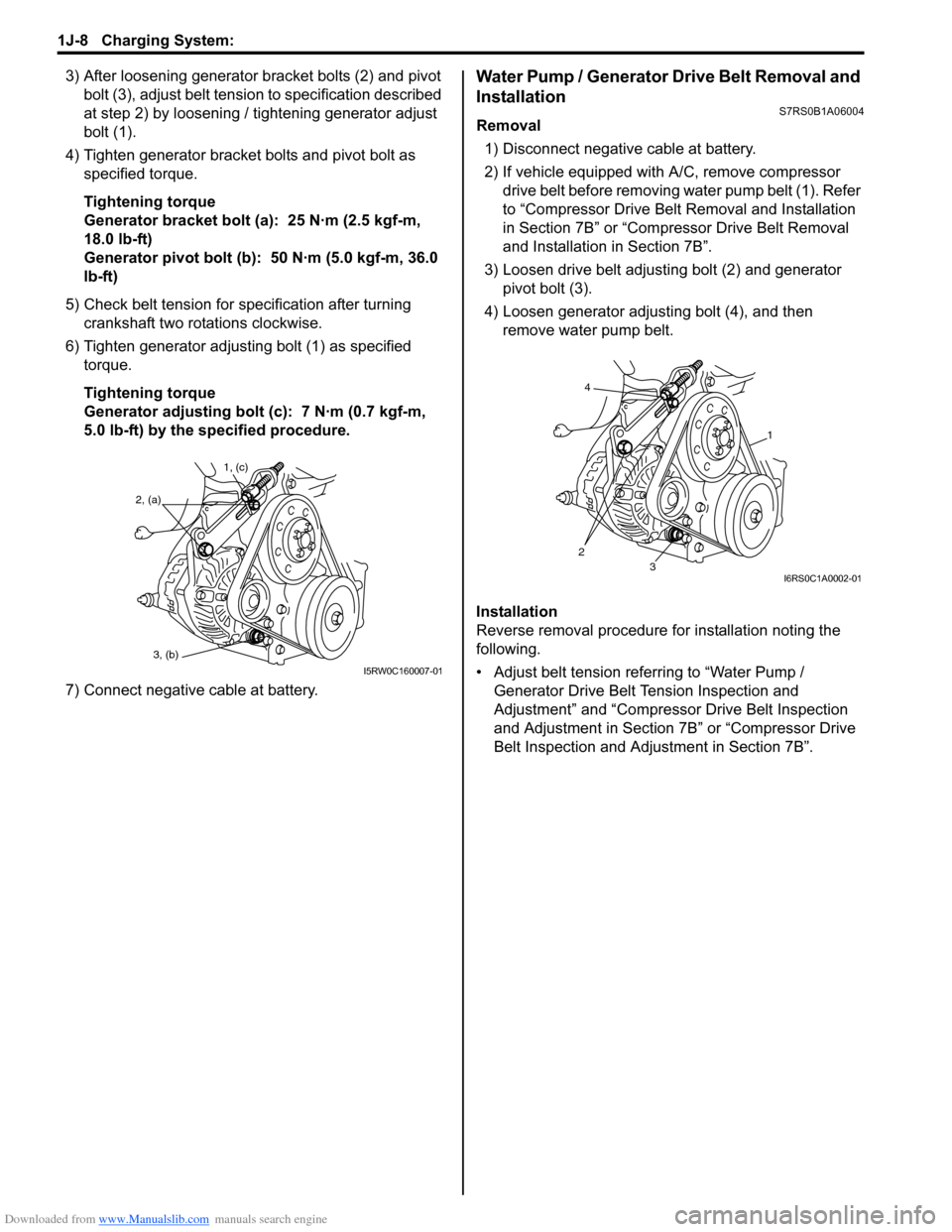
3) After loosening generator bracket bolts (2) and pivot bolt (3), adjust belt tensio n to specification described
at step 2) by loosening / tightening generator adjust
bolt (1).
4) Tighten generator bracket bolts and pivot bolt as specified torque.
Tightening torque
Generator bracket bolt (a): 25 N·m (2.5 kgf-m,
18.0 lb-ft)
Generator pivot bolt (b): 50 N·m (5.0 kgf-m, 36.0
lb-ft)
5) Check belt tension for specification after turning crankshaft two rotations clockwise.
6) Tighten generator adjusting bolt (1) as specified torque.
Tightening torque
Generator adjusting bolt (c): 7 N·m (0.7 kgf-m,
5.0 lb-ft) by the specified procedure.
7) Connect negative cable at battery.Water Pump / Generator Drive Belt Removal and
Installation
S7RS0B1A06004
Removal 1) Disconnect negative cable at battery.
2) If vehicle equipped with A/C, remove compressor drive belt before removing water pump belt (1). Refer
to “Compressor Drive Belt Removal and Installation
in Section 7B” or “Compr essor Drive Belt Removal
and Installation in Section 7B”.
3) Loosen drive belt adjusting bolt (2) and generator pivot bolt (3).
4) Loosen generator adjusting bolt (4), and then remove water pump belt.
Installation
Reverse removal procedure for installation noting the
following.
• Adjust belt tension referring to “Water Pump / Generator Drive Belt Tension Inspection and
Adjustment” and “Compressor Drive Belt Inspection
and Adjustment in Section 7B” or “Compressor Drive
Belt Inspection and Adjustment in Section 7B”.
1, (c)
2, (a)
3, (b)
I5RW0C160007-01
4
23
1
I6RS0C1A0002-01
Page 423 of 1496
Downloaded from www.Manualslib.com manuals search engine Charging System: 1J-13
Specifications
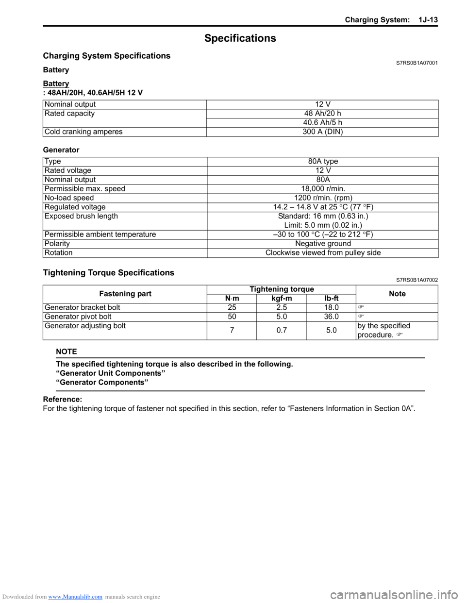
Charging System SpecificationsS7RS0B1A07001
Battery
Battery
: 48AH/20H, 40.6AH/5H 12 V
Generator
Tightening Torque SpecificationsS7RS0B1A07002
NOTE
The specified tightening torque is also described in the following.
“Generator Unit Components”
“Generator Components”
Reference:
For the tightening torque of fastener not specified in this section, refer to “Fasteners Information in Section 0A”.
Nominal output
12 V
Rated capacity 48 Ah/20 h
40.6 Ah/5 h
Cold cranking amperes 300 A (DIN)
Ty p e 80A type
Rated voltage 12 V
Nominal output 80A
Permissible max. speed 18,000 r/min.
No-load speed 1200 r/min. (rpm)
Regulated voltage 14.2 – 14.8 V at 25 ° C (77 °F)
Exposed brush length Standard: 16 mm (0.63 in.)
Limit: 5.0 mm (0.02 in.)
Permissible ambient temperature –30 to 100 °C (–22 to 212 °F)
Polarity Negative ground
Rotation Clockwise viewed from pulley side
Fastening partTightening torque
Note
N ⋅mkgf-mlb-ft
Generator bracket bolt 25 2.5 18.0 �)
Generator pivot bolt 50 5.0 36.0 �)
Generator adjusting bolt 70.7 5.0by the specified
procedure.
�)
Page 425 of 1496
Downloaded from www.Manualslib.com manuals search engine Exhaust System: 1K-2
Repair Instructions
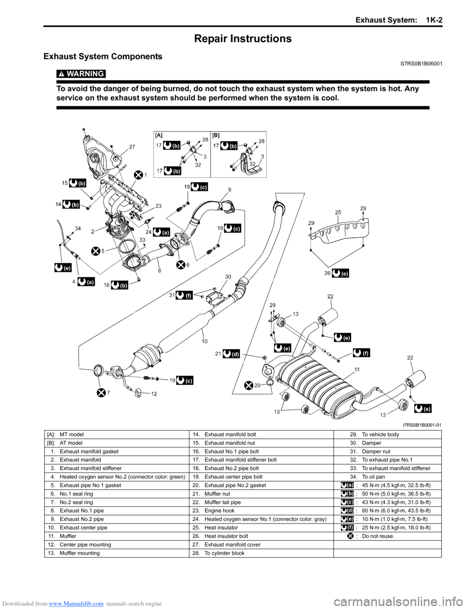
Exhaust System ComponentsS7RS0B1B06001
WARNING!
To avoid the danger of being burned, do not touch the exhaust system when the system is hot. Any
service on the exhaust system should be performed when the system is cool.
I7RS0B1B0001-01
[A]: MT model14. Exhaust manifold bolt 29. To vehicle body
[B]: AT model 15. Exhaust manifold nut 30. Damper
1. Exhaust manifold gasket 16. Exhaust No.1 pipe bolt 31. Damper nut
2. Exhaust manifold 17. Exhaust manifold stiffener bolt 32. To exhaust pipe No.1
3. Exhaust manifold stiffener 18. Exhaust No.2 pipe bolt 33. To exhaust manifold stiffener
4. Heated oxygen sensor No.2 (connector color: green) 19. Exhaust center pipe bolt 34. To oil pan
5. Exhaust pipe No.1 gasket 20. Exhaust pipe No.2 gasket : 45 N⋅m (4.5 kgf-m, 32.5 lb-ft)
6. No.1 seal ring 21. Muffler nut : 50 N⋅m (5.0 kgf-m, 36.5 lb-ft)
7. No.2 seal ring 22. Muffler tail pipe : 43 N⋅m (4.3 kgf-m, 31.0 lb-ft)
8. Exhaust No.1 pipe 23. Engine hook : 60 N⋅m (6.0 kgf-m, 43.5 lb-ft)
9. Exhaust No.2 pipe 24. Heated oxygen sensor No.1 (connector color: gray) : 10 N⋅m (1.0 kgf-m, 7.5 lb-ft)
10. Exhaust center pipe 25. Heat insulator : 25 N⋅m (2.5 kgf-m, 18.0 lb-ft)
11. Muffler 26. Heat insulator bolt : Do not reuse.
12. Center pipe mounting 27. Exhaust manifold cover
13. Muffler mounting 28. To cylinder block
Page 436 of 1496
Downloaded from www.Manualslib.com manuals search engine 2B-3 Front Suspension:
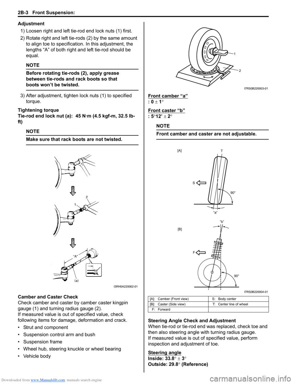
Adjustment1) Loosen right and left tie-rod end lock nuts (1) first.
2) Rotate right and left tie-rods (2) by the same amount to align toe to specification. In this adjustment, the
lengths “A” of both right and left tie-rod should be
equal.
NOTE
Before rotating tie-rods (2), apply grease
between tie-rods and rack boots so that
boots won’t be twisted.
3) After adjustment, tighten lock nuts (1) to specified torque.
Tightening torque
Tie-rod end lock nut (a): 45 N·m (4.5 kgf-m, 32.5 lb-
ft)
NOTE
Make sure that rack boots are not twisted.
Camber and Caster Check
Check camber and caster by camber caster kingpin
gauge (1) and turning radius gauge (2).
If measured value is out of specified value, check
following items for damage, deformation and crack.
• Strut and component
• Suspension control arm and bush
• Suspension frame
• Wheel hub, steering knuckle or wheel bearing
• Vehicle body Front camber “a”
: 0
± 1°
Front caster “b”
: 5 °12’ ± 2°
NOTE
Front camber and caster are not adjustable.
Steering Angle Check and Adjustment
When tie-rod or tie-rod end was replaced, check toe and
then also steering angle with turning radius gauge.
If measured value is out of specified value, perform
inspection and adjustment of toe.
Steering angle
Inside: 33.8 ° ± 3 °
Outside: 29.8 ° (Reference)
I3RH0A220002-01
[A]: Camber (Front view) S: Body center
[B]: Caster (Side view) T: Center line of wheel
F: Forward
2
1
I7RS0B220003-01
[B]
S T
90°
“a”
[A]
F
90°
“b”
I7RS0B220004-01