1-10 SUZUKI SWIFT 2007 2.G Service Workshop Manual
[x] Cancel search | Manufacturer: SUZUKI, Model Year: 2007, Model line: SWIFT, Model: SUZUKI SWIFT 2007 2.GPages: 1496, PDF Size: 34.44 MB
Page 986 of 1496
Downloaded from www.Manualslib.com manuals search engine 7B-38 Air Conditioning System: Automatic Type
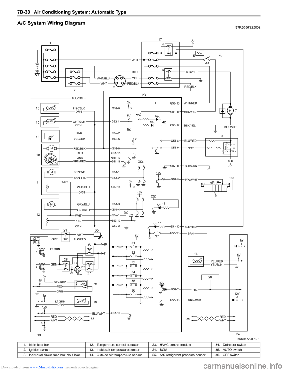
A/C System Wiring DiagramS7RS0B7222002
6
13
15
1610
11
12 9
12V
5V
5V5V
12V
12V
5V 5V
5V +BB
PNK/BLK
WHT/BLK
GRYBLK
WHT/BLU
WHT YEL
ORN
BRN/WHT
BRN/YEL
GRY/BLU
GRY/RED
PNK
YEL/BLK
BLK/ORN
PPL/WHT
12V BLK/YEL
WHT
ORN
ORN
ORN
5V
BLK/RED
BRN
RED/BLK
5V
5VGRY/REDRED
ORN
BLU/WHT
14
YEL/REDYEL/BLK
GRN/WHT
12V
YEL
L+
H+
L
H
WHTGRYBLK/RED
REDWHTREDWHT
M
M
WHT/RED
5
BLU
YEL
WHT
WHT/BLU
RED/BLKWHT
RED/YEL
BLU/YEL
LT GRN
GRN
BLU/RED
G52-6
G52-4
G52-2
G52-5
G51-1
G51-2
G52-14
G51-3
G51-4
G52-1
G52-13
G52-3
G51-19
G51-7
G51-18
G51-10
G51-20
G51-5
G52-11
G51-9
G51-8
G51-12
G51-11
G52-16
5V
12V
5V
12V
LT GRNORN
5V
23
1
2
3 4
8
17
18 19
20
21
22
24
25
26
27
28
29
30
36 35 34 33 32 31 37
38 3938
41 40
42
43
44
MRED/BLK
GRN/RED
G52-8G51-15
G51-17G51-16
REDGRN
BLK/YEL
BLK/WHT
M7
I7RS0A722001-01
1. Main fuse box 12. Temperature control actuator 23. HVAC control module 34. Defroster switch
2. Ignition switch 13. Inside air temperature sensor 24. BCM 35. AUTO switch
3. Individual circuit fuse box No.1 box 14. Outside air temper ature sensor 25. A/C refrigerant pressure sensor 36. OFF switch
Page 1016 of 1496
Downloaded from www.Manualslib.com manuals search engine 7B-68 Air Conditioning System: Automatic Type
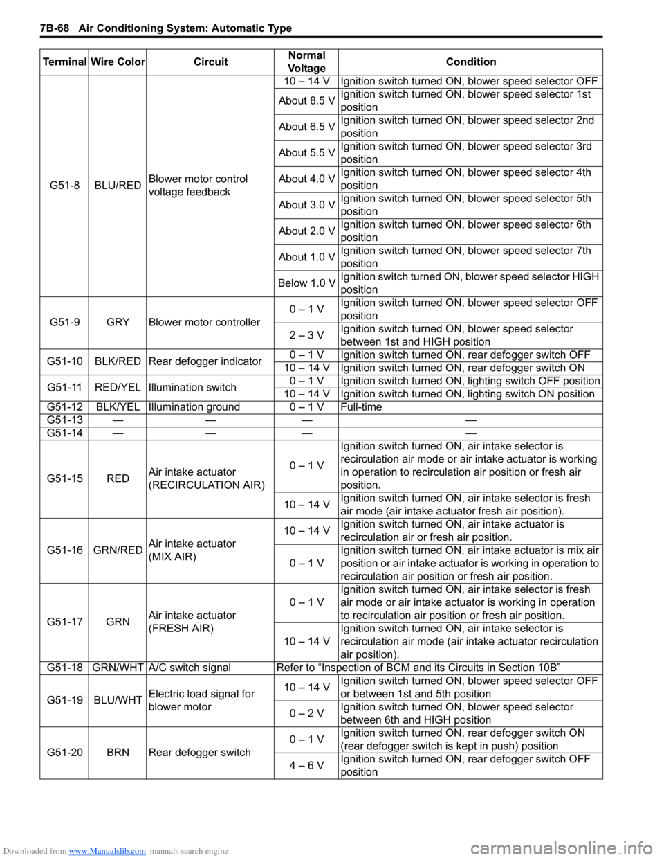
G51-8 BLU/REDBlower motor control
voltage feedback 10 – 14 V Ignition switch turned ON, blower speed selector OFF
About 8.5 V Ignition switch turned ON, blower speed selector 1st
position
About 6.5 V Ignition switch turned ON, blower speed selector 2nd
position
About 5.5 V Ignition switch turned ON, blower speed selector 3rd
position
About 4.0 V Ignition switch turned ON, blower speed selector 4th
position
About 3.0 V Ignition switch turned ON, blower speed selector 5th
position
About 2.0 V Ignition switch turned ON, blower speed selector 6th
position
About 1.0 V Ignition switch turned ON, blower speed selector 7th
position
Below 1.0 V Ignition switch turned ON, blower speed selector HIGH
position
G51-9 GRY Blower motor controller 0 – 1 V
Ignition switch turned ON, blower speed selector OFF
position
2 – 3 V Ignition switch turned ON, blower speed selector
between 1st and HIGH position
G51-10 BLK/RED Rear defogger indicator 0 – 1 V Ignition switch turned ON, rear defogger switch OFF
10 – 14 V Ignition switch turned ON, rear defogger switch ON
G51-11 RED/YEL Illumination switch 0 – 1 V Ignition switch turned ON, lighting switch OFF position
10 – 14 V Ignition switch turned ON, lighting switch ON position
G51-12 BLK/YEL Illumination ground 0 – 1 V Full-time
G51-13 — — — —
G51-14 — — — —
G51-15 RED Air intake actuator
(RECIRCULATION AIR) 0 – 1 VIgnition switch turned ON, air intake selector is
recirculation air mode or air intake actuator is working
in operation to recirculation air position or fresh air
position.
10 – 14 V Ignition switch turned ON, ai
r intake selector is fresh
air mode (air intake actuator fresh air position).
G51-16 GRN/RED Air intake actuator
(MIX AIR) 10 – 14 V
Ignition switch turned ON, air intake actuator is
recirculation air or fresh air position.
0 – 1 V Ignition switch turned ON, air intake actuator is mix air
position or air intake actuator is working in operation to
recirculation air position or fresh air position.
G51-17 GRN Air intake actuator
(FRESH AIR) 0 – 1 V
Ignition switch turned ON, ai
r intake selector is fresh
air mode or air intake actuator is working in operation
to recirculation air position or fresh air position.
10 – 14 V Ignition switch turned ON, air intake selector is
recirculation air mode (air intake actuator recirculation
air position).
G51-18 GRN/WHT A/C switch signal Refer to “Inspe ction of BCM and its Circuits in Section 10B”
G51-19 BLU/WHT Electric load signal for
blower motor 10 – 14 V
Ignition switch turned ON, blower speed selector OFF
or between 1st and 5th position
0 – 2 V Ignition switch turned ON, blower speed selector
between 6th and HIGH position
G51-20 BRN Rear defogger switch 0 – 1 V
Ignition switch turned ON, rear defogger switch ON
(rear defogger switch is kept in push) position
4 – 6 V Ignition switch turned ON, rear defogger switch OFF
position
Terminal Wire Color Circuit
Normal
Vo l ta g e Condition
Page 1408 of 1496
Downloaded from www.Manualslib.com manuals search engine 10B-5 Body Electrical Control System:
GRY/RED
BLK/YEL
BLK/RED
12V
12V
+BB
BLU/YEL
BLU
12V
WHT/BLU
12V
+BB
RED/YEL
G34-7
YEL/REDYEL/BLK
5V
IG1
IG1
IG1
WASH
OFFINT ON
WASH, ON WR EWON
INT
BLU/BLK
YELE39-9
GRN
12V12V
YELL05-5
BLU/YEL
PPL/WHT
12V
G37-5PPL/WHTPPL/WHT
+B +B
GRN/RED
GRN
GRN
RED/BLU
L06-9
L06-10
L01-10L01-1
ON
DOOR
OFF+B
+B
IG1 WHT
K01-5
12V
12V
12V
5V
12V
12V
L04-2YEL
RED/BLK
WHT
GRN/WHT
BRN
LT GRN/BLK
BRN
GRY/WHT
GRY
12VLT GRN
12V
12V
12V
12V
RED/BLK
LT GRN
BRN/WHT
5V5V
5V
PNK
+BB
GRNG32-2
+B
BLKBLK/ORNG34-9
G33-3
BLK/ORNL05-4
BLU
G32-5
WHTE40-2
G34-11
E41-3G34-3BLU
REDWHTREDWHT
+BB
1
2 3
4
5 67
8
9
10
11 12
13 14 14 14 15
16
17
18
19
20
21
22
23
24
52
51 25
26
28
30
31
32
33
33 36 36
+B
GRN
RED/BLU
L06-9
L06-10
33
36 3635 34
35 34
37 50 38
39
40
45 46
47
48 49
[B] [A]
[C]
G37-21
E46-10
GRY
YEL
BRN/YEL
L01-12
L01-4
L01-8
L01-11
GRN
WHT
G37-22
E46-4
G37-8
E46-8
G37-16
E46-11
G37-11
G37-13
G37-14
G37-12
L01-7
L01-15
L01-3
L01-14
L01-16
E46-5
L01-6
L01-17
L01-5
G37-17
G37-18
E46-1E46-2
E46-9
+B
12V
12V
BLK/RED
BLK/REDL05-6
G33-7 54
BLK/REDL05-7
55
BLK/REDL05-842
43
44
27REDWHT
57
+B41
56
ORNL05-9
L04-3
REDWHTREDWHT
REDWHT
REDWHT
G37-4G37-2
RED/BLKWHT/BLKG37-3G37-1 58
59
29
53
I7RS0BA20003-02
Page 1435 of 1496
Downloaded from www.Manualslib.com manuals search engine Body Electrical Control System: 10B-32
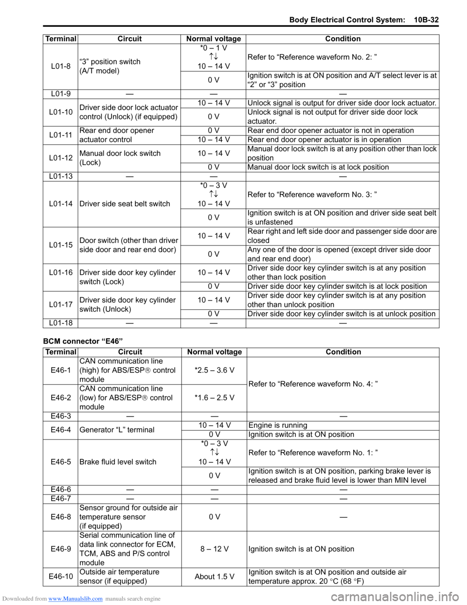
BCM connector “E46”L01-8
“3” position switch
(A/T model) *0 – 1 V
↑↓
10 – 14 V Refer to “Reference waveform No. 2: ”
0 V Ignition switch is at ON positi
on and A/T select lever is at
“2” or “3” position
L01-9 — — —
L01-10 Driver side door lock actuator
control (Unlock) (if equipped) 10 – 14 V Unlock signal is output for driver side door lock actuator.
0 V Unlock signal is not output for driver side door lock
actuator.
L01-11 Rear end door opener
actuator control 0 V Rear end door opener actuator is not in operation
10 – 14 V Rear end door opener actuator is in operation
L01-12 Manual door lock switch
(Lock) 10 – 14 V
Manual door lock switch is at any position other than lock
position
0 V Manual door lock swit ch is at lock position
L01-13 — — —
L01-14 Driver side seat belt switch *0 – 3 V
↑↓
10 – 14 V Refer to “Reference waveform No. 3: ”
0 V Ignition switch is at ON position and driver side seat belt
is unfastened
L01-15 Door switch (other than driver
side door and rear end door) 10 – 14 V
Rear right and left side door and passenger side door are
closed
0 V Any one of the door is opened (except driver side door
and rear end door)
L01-16 Driver side door key cylinder switch (Lock) 10 – 14 V
Driver side door key cylinder switch is at any position
other than lock position
0 V Driver side door key cylinder switch is at lock position
L01-17 Driver side door key cylinder
switch (Unlock) 10 – 14 V
Driver side door key cylinder switch is at any position
other than unlock position
0 V Driver side door key cylinder switch is at unlock position
L01-18 — — —
Terminal Circuit Normal voltage Condition
Terminal
CircuitNormal voltage Condition
E46-1 CAN communication line
(high) for ABS/ESP
® control
module *2.5 – 3.6 V
Refer to “Reference waveform No. 4: ”
E46-2 CAN communication line
(low) for ABS/ESP
® control
module *1.6 – 2.5 V
E46-3 — — —
E46-4 Generator “L” terminal 10 – 14 V Engine is running
0 V Ignition switch is at ON position
E46-5 Brake fluid level switch *0 – 3 V
↑↓
10 – 14 V Refer to “Reference waveform No. 1: ”
0 V Ignition switch is at ON position, parking brake lever is
released and brake fluid level is lower than MIN level
E46-6 — — —
E46-7 — — —
E46-8 Sensor ground for outside air
temperature sensor
(if equipped) 0 V
—
E46-9 Serial communication line of
data link connector for ECM,
TCM, ABS and
P/S control
module 8 – 12 V Ignition switch is at ON position
E46-10 Outside air temperature
sensor (if equipped) About 1.5 VIgnition switch is at ON position and outside air
temperature approx. 20
°C (68 °F)