10E SUZUKI SWIFT 2007 2.G Service Workshop Manual
[x] Cancel search | Manufacturer: SUZUKI, Model Year: 2007, Model line: SWIFT, Model: SUZUKI SWIFT 2007 2.GPages: 1496, PDF Size: 34.44 MB
Page 4 of 1496

Downloaded from www.Manualslib.com manuals search engine 00
0
1
2
3
4
5
6
7
8
9
10
11
Vo l u m e 1
Precautions............................................................... 00-iPrecautions ............................................................ 00-1
General Information ................ ................................... 0-i
General Information ............................................... 0A-1
Maintenance and Lubricatio n ................................. 0B-1
Engine ......................................................................... 1-i Precautions .............................................................. 1-1
Engine General Information and Diagnosis ........... 1A-1
Aux. Emission Control Devices .............................. 1B-1
Engine Electrical Devices....................................... 1C-1
Engine Mechanical ................................................. 1D-1
Engine Lubrication System .................................... 1E-1
Engine Cooling System .......................................... 1F-1
Fuel System ...........................................................1G-1
Ignition System....................................................... 1H-1
Starting System ....................................................... 1I-1
Charging System.....................................................1J-1
Exhaust System ..................................................... 1K-1
Suspension ................................................................. 2-i Precautions .............................................................. 2-1
Suspension General Diagnosis .............................. 2A-1
Front Suspension ................................................... 2B-1
Rear Suspension................ .................................... 2C-1
Wheels and Tires ................................................... 2D-1
Driveline / Axle ........................................................... 3-i Precautions .............................................................. 3-1
Drive Shaft / Axle ................................................... 3A-1
Brakes ......................................................................... 4-i Precautions .............................................................. 4-1
Brake Control System and Diagnosis .................... 4A-1
Front Brakes........................................................... 4B-1
Rear Brakes ........................................................... 4C-1
Parking Brake......................................................... 4D-1
ABS ........................................................................ 4E-1
Electronic Stability Program ................................... 4F-1
Vo l u m e 2
Precautions ............................................................... 00-iPrecautions ............................................................ 00-1
Transmission / Transaxle .... ...................................... 5-i
Precautions .............................................................. 5-1
Automatic Transmission/Transaxle ........................ 5A-1
Manual Transmission/Transaxle ............................ 5B-1
Clutch .....................................................................5C-1
Steering ....................................................................... 6-i Precautions .............................................................. 6-1
Steering General Diagnosis ................................... 6A-1
Steering Wheel and Column .................................. 6B-1
Power Assisted Steering System ...........................6C-1
HVAC ........................................................................... 7-i Precautions .............................................................. 7-1
Heater and Ventilation............................................ 7A-1
Air Conditioning System ......................................... 7B-1
Restraint ...................................................................... 8-i Precautions .............................................................. 8-1
Seat Belts ............................................................... 8A-1
Air Bag System ...................................................... 8B-1
Body, Cab and Accessories .... .................................. 9-i
Precautions .............................................................. 9-1
Wiring Systems ...................................................... 9A-1
Lighting Systems .................................................... 9B-1
Instrumentation / Driver Info. / Horn .......................9C-1
Wipers / Washers ...................................................9D-1
Glass / Windows / Mirrors ...................................... 9E-1
Security and Locks ................................................. 9F-1
Seats ..................................................................... 9G-1
Interior Trim ............................................................9H-1
Hood / Fenders / Doors .......................................... 9J-1
Body Structure ....................................................... 9K-1
Paint / Coatings ...................................................... 9L-1
Exterior Trim .......................................................... 9M-1
Control Systems ....................................................... 10-i Precautions ............................................................ 10-1
Body Electrical Control Sy stem ............................ 10B-1
Immobilizer Control System .................................10C-1
Keyless Start System ........................................... 10E-1
TABLE OF CONTENTS
Page 88 of 1496
Downloaded from www.Manualslib.com manuals search engine 1A-38 Engine General Information and Diagnosis:
Engine Basic InspectionS7RS0B1104009
This check is very important for troubleshooting when ECM has detected no DTC and no abnormality has been found
in “Visual Inspection”.
Follow the flow carefully.Step Action Yes No 1 Was “Engine and Emission Control System Check”
performed? Go to Step 2. Go to “Engine and
Emission Control
System Check”.
2 Check battery voltage
Is it 11 V or more? Go to Step 3. Charge or replace
battery.
3 Is vehicle equipped with keyless start control system? Go to Step 4. Go to Step 5.
4 Check keyless start control system malfunction
1) Check keyless start control system referring to “Keyless
Start System Operation In spection in Section 10E”.
Is check result satisfactory? Go to Step 5. Keyless start control
system malfunction.
5 Is engine cranked? Go to Step 6. Go to “Cranking System
Symptom Diagnosis in
Section 1I”.
6 Does engine start? Go to Step 7. Go to Step 9.
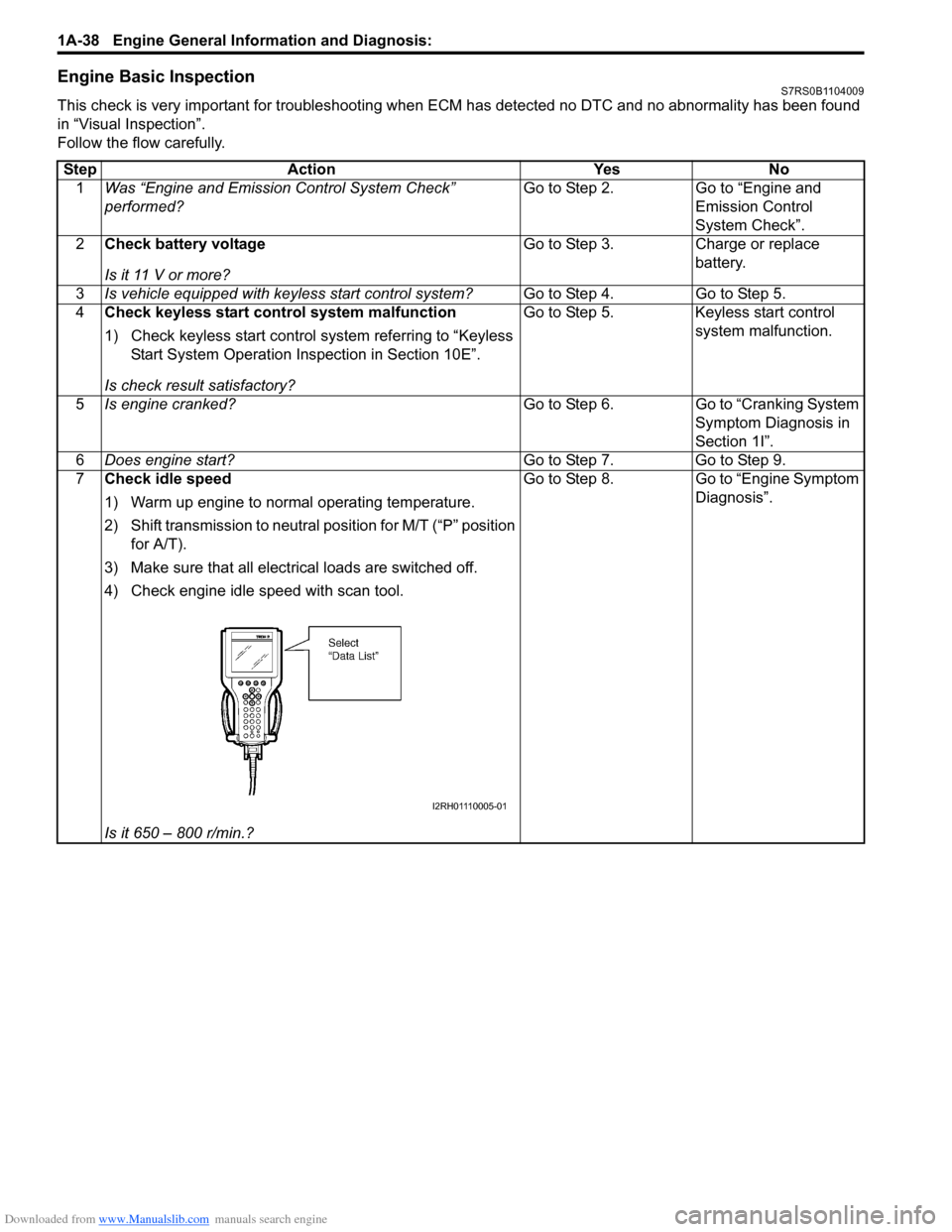
7 Check idle speed
1) Warm up engine to normal operating temperature.
2) Shift transmission to neutral position for M/T (“P” position
for A/T).
3) Make sure that all electrical loads are switched off.
4) Check engine idle speed with scan tool.
Is it 650 – 800 r/min.? Go to Step 8. Go to “Engine Symptom
Diagnosis”.
I2RH01110005-01
Page 196 of 1496
Downloaded from www.Manualslib.com manuals search engine 1A-146 Engine General Information and Diagnosis:
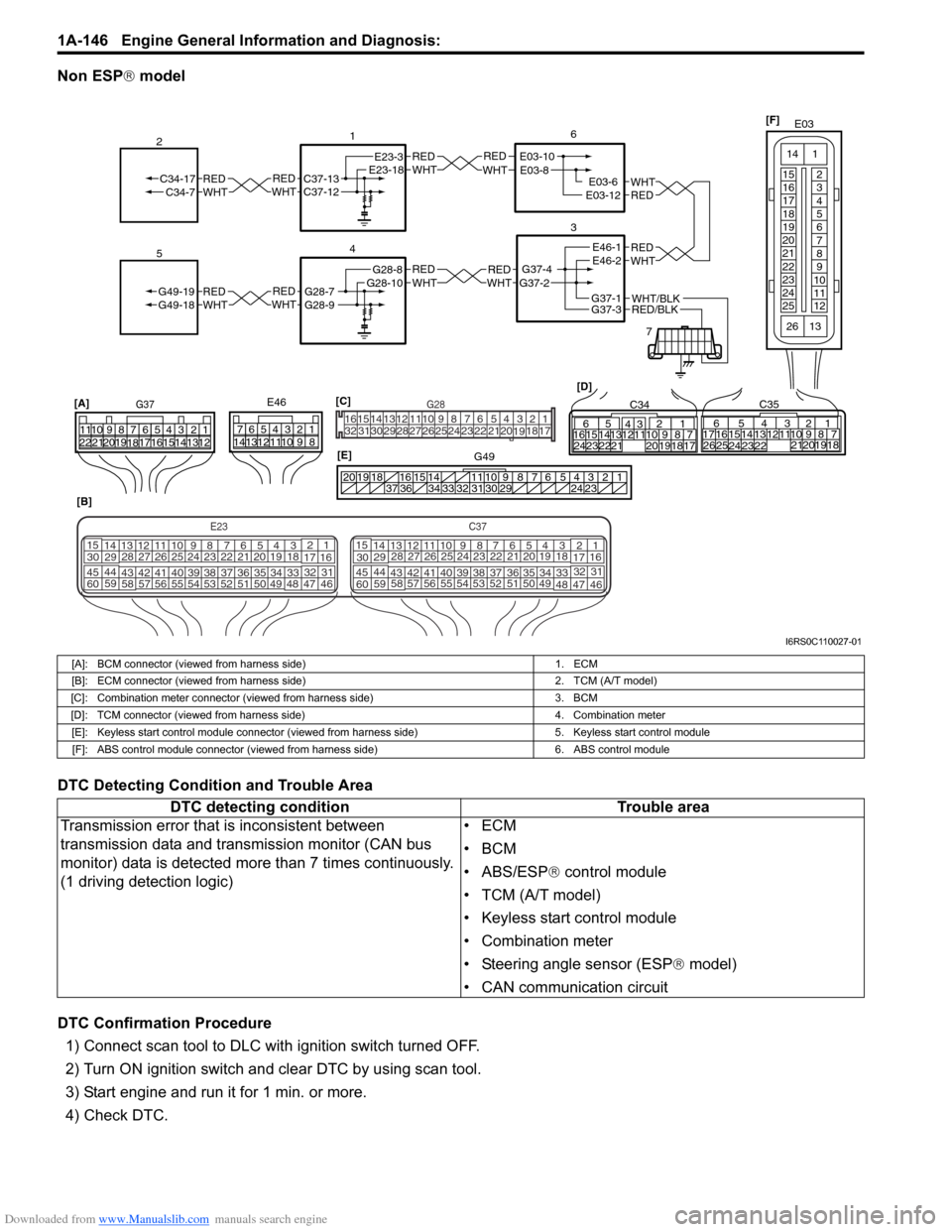
Non ESP® model
DTC Detecting Condition and Trouble Area
DTC Confirmation Procedure 1) Connect scan tool to DLC with ignition switch turned OFF.
2) Turn ON ignition switch and clear DTC by using scan tool.
3) Start engine and run it for 1 min. or more.
4) Check DTC.
REDWHTE03-6E03-12
6
3
7
REDWHT
1
[B]
[A]
G37E46
1234567
1234567
891011
891011
121314 121314
151617
18
19202122 [D]65
1615 14131211 43
2423 2122 10 9 8 7
21
1920 1817
C3417 16
26 2515 14
65 3
42
13 12
23 2224 1110 9
212019 87
18
1
C35
[E]
REDWHTC37-13C37-12REDWHTC34-17C34-7
2
1234567891011
141516
36 34 33 32 31 30 29 24 23
37
181920
[C] [F]
G49
E23-3E23-18
4
REDWHTG28-7G28-9REDWHTG49-19G49-18
5
REDWHTE03-10E03-8
G37-4G37-2
REDWHTE46-1E46-2REDWHTREDWHTG28-8G28-10
RED/BLKWHT/BLKG37-3G37-1
E03
15
16
17
18
19
20
21
22
23
24
25 2
3
4
5
6
7
8
9
10
11
12
1
13
14
26
E23C37
34
1819
567
1011
17
20
47 46
495051
2122
52 16
25 9
24
14
29
5557 54 53
59
60 58 2
262728
15
30
56 4832 31
34353637
4042 39 38
44
45 43 41 33 1
1213
238
34
1819
567
1011
17
20
47 46
495051
2122
52 16
25 9
24
14
29
5557 54 53
59
60 58 2
262728
15
30
56 4832 31
34353637
4042 39 38
44
45 43 41 331
1213
238
G281234567
8
910111213141516
1718
19
20
212223242526272829303132
I6RS0C110027-01
[A]: BCM connector (viewed from harness side) 1. ECM
[B]: ECM connector (viewed from harness side) 2. TCM (A/T model)
[C]: Combination meter connector (viewed from harness side) 3. BCM
[D]: TCM connector (viewed from harness side) 4. Combination meter
[E]: Keyless start control module connector (viewed from harness side) 5. Keyless start control module
[F]: ABS control module connector (viewed from harness side) 6. ABS control module
DTC detecting conditionTrouble area
Transmission error that is inconsistent between
transmission data and transmission monitor (CAN bus
monitor) data is detected more than 7 times continuously.
(1 driving detection logic) •ECM
•BCM
• ABS/ESP®
control module
• TCM (A/T model)
• Keyless start control module
• Combination meter
• Steering angle sensor (ESP ® model)
• CAN communication circuit
Page 544 of 1496
Downloaded from www.Manualslib.com manuals search engine 4E-5 ABS:
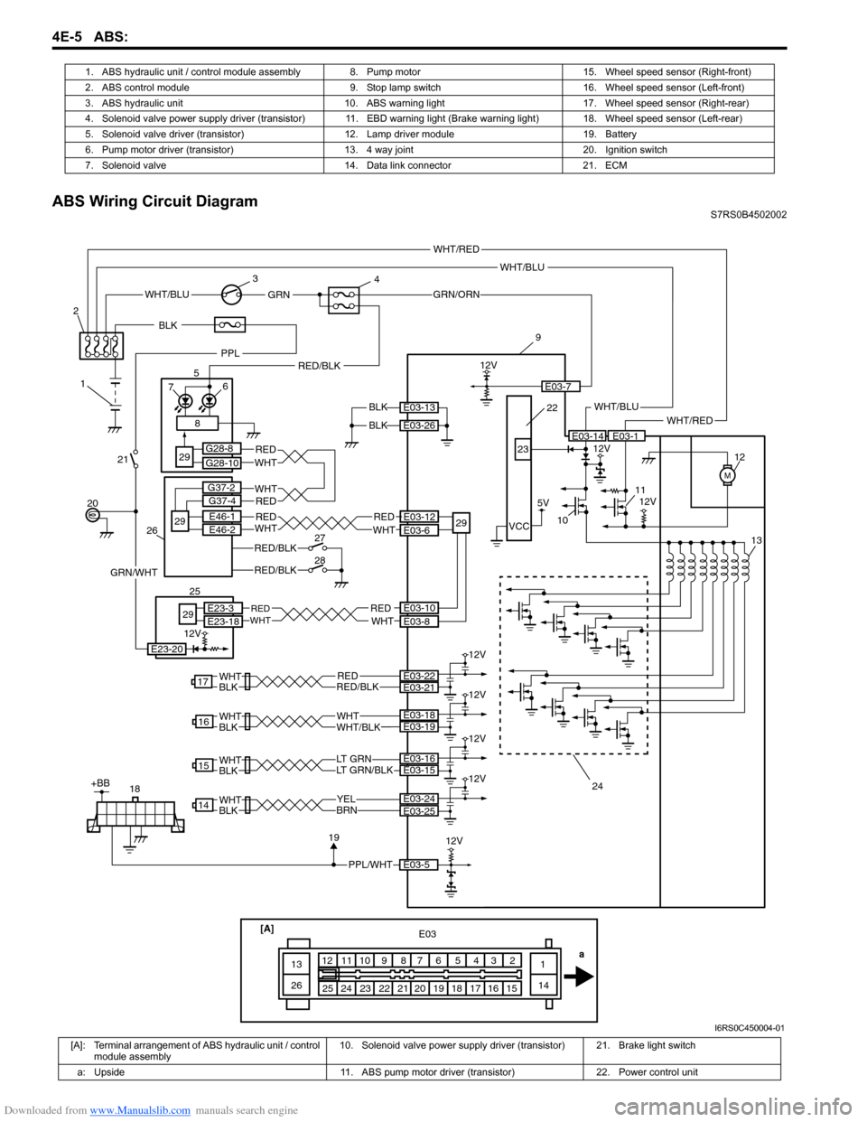
ABS Wiring Circuit DiagramS7RS0B4502002
1. ABS hydraulic unit / control module assembly 8.
Pump motor 15. Wheel speed sensor (Right-front)
2. ABS control module 9. Stop lamp switch 16. Wheel speed sensor (Left-front)
3. ABS hydraulic unit 10. ABS warning light 17. Wheel speed sensor (Right-rear)
4. Solenoid valve power supply driver (transistor) 11. EBD warnin g light (Brake warning light) 18. Wheel speed sensor (Left-rear)
5. Solenoid valve driver (transistor) 12. Lamp driver module 19. Battery
6. Pump motor driver (transistor) 13. 4 way joint 20. Ignition switch
7. Solenoid valve 14. Data link connector 21. ECM
[A]
14
1516171819202122232425 1
23456789101112
13
26 E03
a
WHT/BLU
BLKWHT/BLU
M
12V
9
10 11 12
13
BLKE03-14E03-1
E03-13
E03-26
YELBRN
14E03-24
LT GRN/BLKLT GRN
15
WHTWHT/BLK
16
RED
WHTBLK
WHTBLK
WHTBLK
WHTBLKRED/BLK
17
12V
PPL/WHT
18E03-5
1912V
5V
12V
23
24
VCC22
E03-25
E03-15E03-16
E03-19E03-18
E03-22E03-21
WHT/RED
WHT/RED
+BB
GRN/ORN
E03-7
WHT/BLUGRN
1
2
3
4
8
RED/BLK
E03-12
E03-6
RED
WHTE03-10E03-8
REDWHT
20 7
6
529
29
G28-8
G28-10
25
29
E23-3E23-18
GRN/WHT
21
PPL
12V
E23-20
12V
12V
12V
12V
REDWHTE46-1
E46-2
BLK
RED/BLK
RED/BLK
RED
RED
WHT
WHT
27
28
26
29
G37-2
G37-4
REDWHT
I6RS0C450004-01
[A]: Terminal arrangement of ABS hydraulic unit / control module assembly 10. Solenoid valve power supply driver
(transistor) 21. Brake light switch
a: Upside 11. ABS pump motor driver (transistor) 22. Power control unit
Page 564 of 1496
Downloaded from www.Manualslib.com manuals search engine 4E-25 ABS:
DTC U1073: Control Module Communication Bus OffS7RS0B4504018
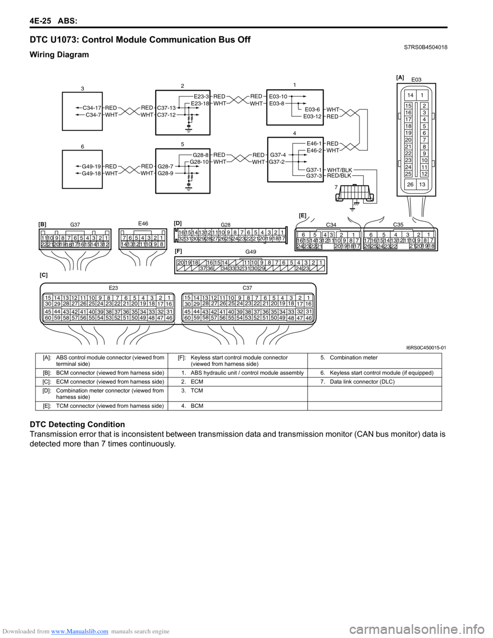
Wiring Diagram
DTC Detecting Condition
Transmission error that is inconsistent between transmission data and transmission monitor (CAN bus monitor) data is
detected more than 7 times continuously.
REDWHTE03-6E03-12
1
4
7
REDWHT
2
[C]
[B]
G37E46
1234567
1234567
891011
891011
121314 121314
151617
18
19202122 [E]65
1615 14131211 43
2423 2122 10 9 8 7
21
1920 1817
C3417 16
26 2515 14
65 3
42
13 12
23 2224 1110 9
212019 87
18
1
C35
[F]
REDWHTC37-13C37-12REDWHTC34-17C34-7
3
1234567891011
141516
36 34 33 32 31 30 29 24 23
37
181920
[D] [A]
G49
E23-3E23-18
5
REDWHTG28-7G28-9REDWHTG49-19G49-18
6
REDWHTE03-10E03-8
G37-4G37-2
REDWHTE46-1E46-2REDWHTREDWHTG28-8G28-10
RED/BLKWHT/BLKG37-3G37-1
E03
15
16
17
18
19
20
21
22
23
24
25 2
3
4
5
6
7
8
9
10
11
12
1
13
14
26
E23C37
34
1819
567
1011
17
20
47 46
495051
2122
52 16
25 9
24
14
29
5557 54 53
59
60 58 2
262728
15
30
56 4832 31
34353637
4042 39 38
44
45 43 41 33 1
1213
238
34
1819
567
1011
17
20
47 46
495051
2122
52 16
25 9
24
14
29
5557 54 53
59
60 58 2
262728
15
30
56 4832 31
34353637
4042 39 38
44
45 43 41 331
1213
238
G281234567
8
910111213141516
1718
19
20
212223242526272829303132
I6RS0C450015-01
[A]: ABS control module connector (viewed from
terminal side) [F]: Keyless start control module connector
(viewed from harness side) 5. Combination meter
[B]: BCM connector (viewed from harness side) 1. ABS hydraulic unit / control module assembly 6. Keyless start control module (if equipped)
[C]: ECM connector (viewed from harness side) 2. ECM 7. Data link connector (DLC)
[D]: Combination meter connector (viewed from harness side) 3. TCM
[E]: TCM connector (viewed from harness side) 4. BCM
Page 713 of 1496
Downloaded from www.Manualslib.com manuals search engine Automatic Transmission/Transaxle: 5A-69
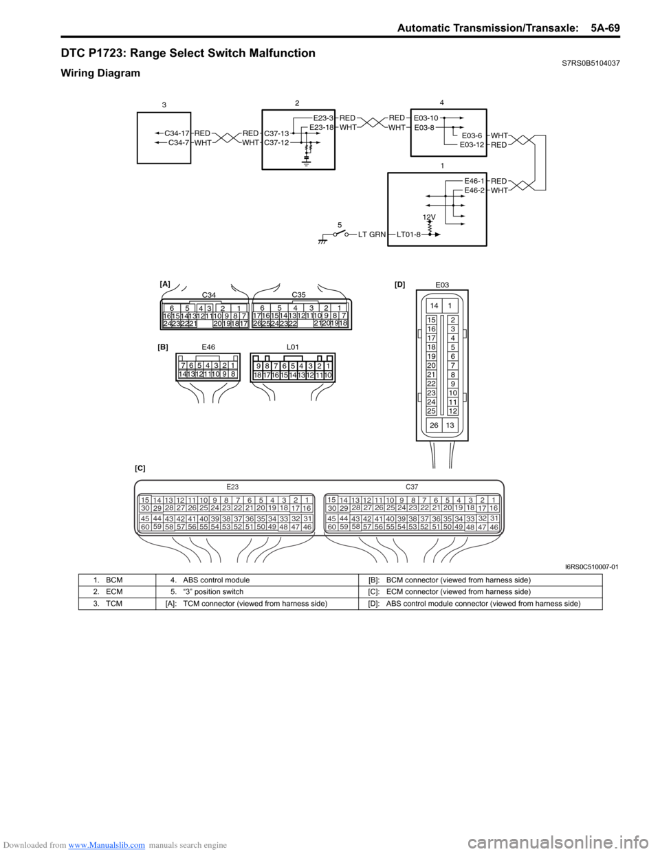
DTC P1723: Range Select Switch MalfunctionS7RS0B5104037
Wiring Diagram
LT01-8
12V
LT GRN
5
REDWHTE03-6E03-12
1
2
REDWHT
4
[D]
[C] [B]
E46
1234567
891011121314
REDWHTC37-13C37-12REDWHTC34-17C34-7
3
32
1110 9
212019 87
18
165
1615 14131211 43
2423 2122 10 9 8 7
21
1920 1817
C3417 16
26 2515 14
654
13 12
23 2224 C35
[A]
E23-3E23-18REDWHTE03-10E03-8
REDWHTE46-1E46-2
E03
15
16
17
18
19
20
21
22
23
24
25 2
3
4
5
6
7
8
9
10
11
12
1
13
14
26
E23C37
34
1819
567
1011
17
20
47 46
495051
2122
52 16
25 9
24
14
29
5557 54 53
59
60 58 2
262728
15
30
56 4832 31
34353637
4042 39 38
44
45 43 41 33 1
1213
238
34
1819
567
1011
17
20
47 46
495051
2122
52 16
25 9
24
14
29
5557 54 53
59
60 58 2
262728
15
30
56 4832 31
34353637
4042 39 38
44
45 43 41 331
1213
238
L01
678
9 54321
15161718 14 13 12 1110
I6RS0C510007-01
1. BCM
4. ABS control module [B]: BCM connector (viewed from harness side)
2. ECM 5. “3” position switch [C]: ECM connector (viewed from harness side)
3. TCM [A]: TCM connector (viewed from harness side) [D]: ABS control module connector (viewed from harness side)
Page 715 of 1496
Downloaded from www.Manualslib.com manuals search engine Automatic Transmission/Transaxle: 5A-71
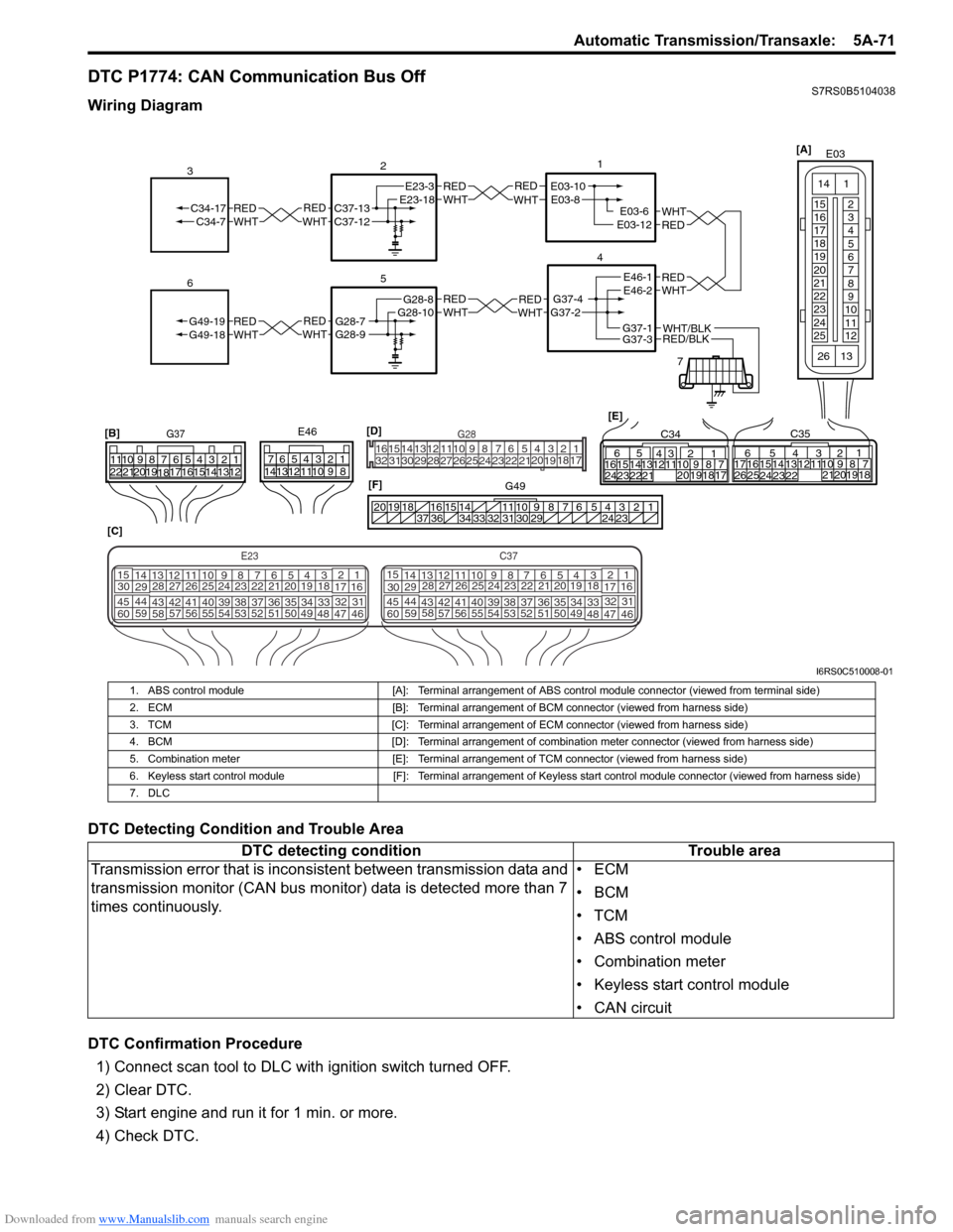
DTC P1774: CAN Communication Bus OffS7RS0B5104038
Wiring Diagram
DTC Detecting Condition and Trouble Area
DTC Confirmation Procedure1) Connect scan tool to DLC with ignition switch turned OFF.
2) Clear DTC.
3) Start engine and run it for 1 min. or more.
4) Check DTC.
REDWHTE03-6E03-12
1
4
7
REDWHT
2
[C]
[B]
G37E46
1234567
1234567
891011
891011
121314 121314
151617
18
19202122 [E]65
1615 14131211 43
2423 2122 10 9 8 7
21
1920 1817
C3417 16
26 2515 14
65 3
42
13 12
23 2224 1110 9
212019 87
18
1
C35
[F]
REDWHTC37-13C37-12REDWHTC34-17C34-7
3
1234567891011
141516
36 34 33 32 31 30 29 24 23
37
181920
[D] [A]
G49
E23-3E23-18
5
REDWHTG28-7G28-9REDWHTG49-19G49-18
6
REDWHTE03-10E03-8
G37-4G37-2
REDWHTE46-1E46-2REDWHTREDWHTG28-8G28-10
RED/BLKWHT/BLKG37-3G37-1
E03
15
16
17
18
19
20
21
22
23
24
25 2
3
4
5
6
7
8
9
10
11
12
1
13
14
26
E23C37
34
1819
567
1011
17
20
47 46
495051
2122
52 16
25 9
24
14
29
5557 54 53
59
60 58 2
262728
15
30
56 4832 31
34353637
4042 39 38
44
45 43 41 33 1
1213
238
34
1819
567
1011
17
20
47 46
495051
2122
52 16
25 9
24
14
29
5557 54 53
59
60 58 2
262728
15
30
56 4832 31
34353637
4042 39 38
44
45 43 41 331
1213
238
G281234567
8
910111213141516
1718
19
20
212223242526272829303132
I6RS0C510008-01
1. ABS control module [A]: Terminal arrangement of ABS control module connector (viewed from terminal side)
2. ECM [B]: Terminal arrangement of BCM connector (viewed from harness side)
3. TCM [C]: Terminal arrangement of ECM connector (viewed from harness side)
4. BCM [D]: Terminal arrangement of combination meter connector (viewed from harness side)
5. Combination meter [E]: Terminal arrangement of TCM connector (viewed from harness side)
6. Keyless start control module [F]: Terminal arrangement of Keyless start control module connector (viewed from harness side)
7. DLC
DTC detecting condition Trouble area
Transmission error that is incons istent between transmission data and
transmission monitor (CAN bus monitor) data is detected more than 7
times continuously. •ECM
•BCM
•TCM
• ABS control module
• Combination meter
• Keyless start control module
• CAN circuit
Page 1210 of 1496
Downloaded from www.Manualslib.com manuals search engine 9A-39 Wiring Systems:
1IG2FL2
6
Lamp FL (FL BOX)
1A/B CONT4A/B SIG
3K-LINE2A/B SIGNAL
9A/B SIGNAL8K-LINE
2311BCM ;IG1
22D/UL-IN21D/L-IN D/SL-IN
18SECURITY IN6Serial OUT
14TAIL BCM WNG, etc12ANSWER BACK
17RR DEF CONTROL1D/L (+B)
2BCM15DEICER CONTROL
10ACC (BCM)7DOME LP CONT
20GND (POWER)16R-WIP (CONT)
3SIGNAL GND (BCM)
7IG
1LP-L5LP-R
8+B6SW-L
3GND4SW-R
2HAZ
DOME LP POWER5DOME LP DOOR4*3GND (Roof)6HTR4Starter SW1IG 25ACC SW3IG2SW2IG 1
18107G33415G347G3419G341G3412G339G3311G343G342G348G34166G336G345G33810511G3313G344G341G3320G342G339G343G3312G3414G34
10E395E4112E419E4114E411E418E412E4111E413E416E395E3916E417E414E392E399E393E397E3910E41
DEF LP
RR FOG SW DEICER LP
*TAIL SW (Upper)
TAIL SW (HAZ,ASH,ILL) TURN-L
TURN-R
METER (L)
METER (R)
HAZARD SW HORN SW
Serial INF DISP
A/C PANEL
*MTR Power,etc
IMMOBI IG
A/C PANEL
*
*
RADIO, CLOCK
A/B SIGCIGAR
*F-WIP*
*GND (IP)
SIGNAL GND (IP)
*
*
*
IG Coil, etc EPS AT
ABS CONT
BACK (SHIFT) STOP SW
ABS CONT EPI
BUL IN
HORN
FR TURN (R)
FR TURN (L) POSI LP
EPI
DEICER
*F-Washer
F.WIP
HTR Fuse (30A)
ST RLY COIL
4L0515L0516L055L059L05212L0513L0614L067L0615L0614L0511L056L065L068L057L056L0518L053L051L0510L059L0610L061L063L062L068L0611L064L06
SIGNAL GND (FL)
SEAT HEATER
P/W
R-WIP (+) R-WIP (-)*
ACC SOCKET
R/C MIR (ACC)
*
*
*
LUGGAGE LAMPMTA SHIFT LEVER SW
*
*
RR DEF
HTR MIR (L)
HTR MIR (R)
P/W DR
TAIL LP, LICENSE
R-TURN (L)
RR-TURN (R)
D/ULD/L
D-SL
BUL-L
STOP LP
MTA
*
*
IG COIL 15AMETER 10A A/BAG 15A
IG1 SIG 10A ABS 10A
BACK 10A
TAIL 10AD/L 20A
P/WT 20A
RR DEF 20A
DEICER/RR FOG 15A
MTA/HID R 10A
ACC 1 15A
ACC 2 15A
WIPER 15A P/W 30A
*Spare-1
SEAT HTR 15A IG2 SIG 10AST SIG 10A
HAZ-HORN 15A
DIESEL/HID L 10A *Spare-2 RR DEF RLY
DEICER RLY HORN RLY
P-WIP RLY
BLOWER MOTOR RLY
G34 G34
G33
G34
G33
G34 G33
L05
RADIO 15A
To instrument panel harness
(G32) To roof harness
(K01)
To instrument panel
harness
(G33 , G34 )
To main harness
(E39 , E41) To floor harness (L05 , L06 ) To main
harness
(E40)
BCM
To flasher
relay To floor
harness
(L04)
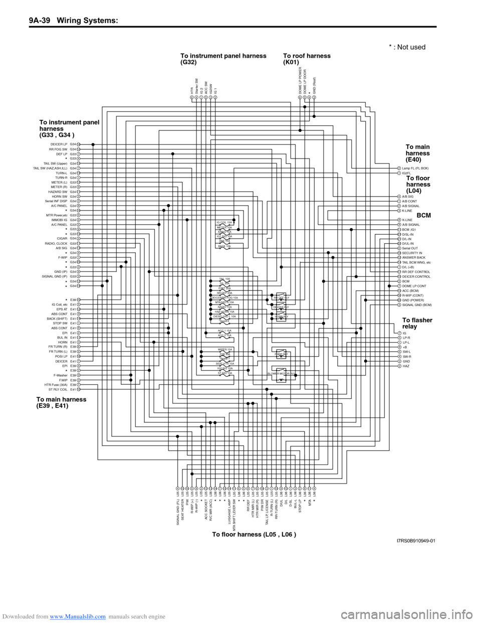
* : Not used
I7RS0B910949-01
Page 1216 of 1496

Downloaded from www.Manualslib.com manuals search engine 9A-45 Wiring Systems:
System Circuit Diagram
System Circuit DiagramS7RS0B910E001
Refer to “A-1 Cranking System Circuit Diagram”.
Refer to “A-2 Charging System Circuit Diagram”.
Refer to “A-3 Ignition System Circuit Diagram”.
Refer to “A-4 Cooling System Circuit Diagram”.
Refer to “A-5 Engine and A/C Control System Circuit Diagram”.
Refer to “A-6 A/T Control System Circuit Diagram”.
Refer to “A-7 Immobilizer System Circuit Diagram”.
Refer to “A-8 Body Control System Circuit Diagram”.
Refer to “B-1 Windshield Wiper and Washer Circuit Diagram”.
Refer to “B-2 Rear Wiper and Washer Circuit Diagram”.
Refer to “B-3 Rear Defogger Circuit Diagram”.
Refer to “B-4 Power Window Circuit Diagram”.
Refer to “B-5 Power Door Lock Circuit Diagram”.
Refer to “B-6 Power Mi rror Circuit Diagram”.
Refer to “B-7 Horn Circuit Diagram”.
Refer to “B-8 Seat Heater Circuit Diagram”.
Refer to “B-9 Keyless Star t System Circuit Diagram”.
Refer to “C-1 Combination Me ter Circuit Diagram (Meter)”.
Refer to “C-2 Combination Mete r Circuit Diagram (Indicator)”.
Refer to “C-3 Combination Meter Circuit Diagram (Warning Light)”.
Refer to “D-1 Headlight System Circuit Diagram”.
Refer to “D-2 Position, Tail and Licence Plate Light System Circuit Diagram”.
Refer to “D-3 Front Fog Light System Circuit Diagram”.
Refer to “D-4 Illumination Light System Circuit Diagram”.
Refer to “D-5 Interior Li ght System Circuit Diagram”.
Refer to “D-6 Turn Signal and Hazard Warning Light System Circuit Diagram”.
Refer to “D-7 Brake Light System Circuit Diagram”.
Refer to “D-8 Back-Up Light System Circuit Diagram”.
Refer to “D-9 Headlight Beam Leveling System Circuit Diagram”.
Refer to “D-10 Rear Fog Light Circuit Diagram”.
Refer to “E-1 Heater System Circuit Diagram”.
Refer to “E-2 Auto A/C System Circuit Diagram”.
Refer to “F-1 Air-Bag System Circuit Diagram”.
Refer to “F-2 Anti-Lock Brake System Circuit Diagram”.
Refer to “F-3 Electronic Stabilit y Program System Circuit Diagram”.
Refer to “F-4 Power Steeri ng System Circuit Diagram”.
Refer to “G-1 Audio Sy stem Circuit Diagram”.
Refer to “G-2 Multi Information Display / Accessory Socket System Circuit Diagram”.
Page 1217 of 1496
Downloaded from www.Manualslib.com manuals search engine Wiring Systems: 9A-46
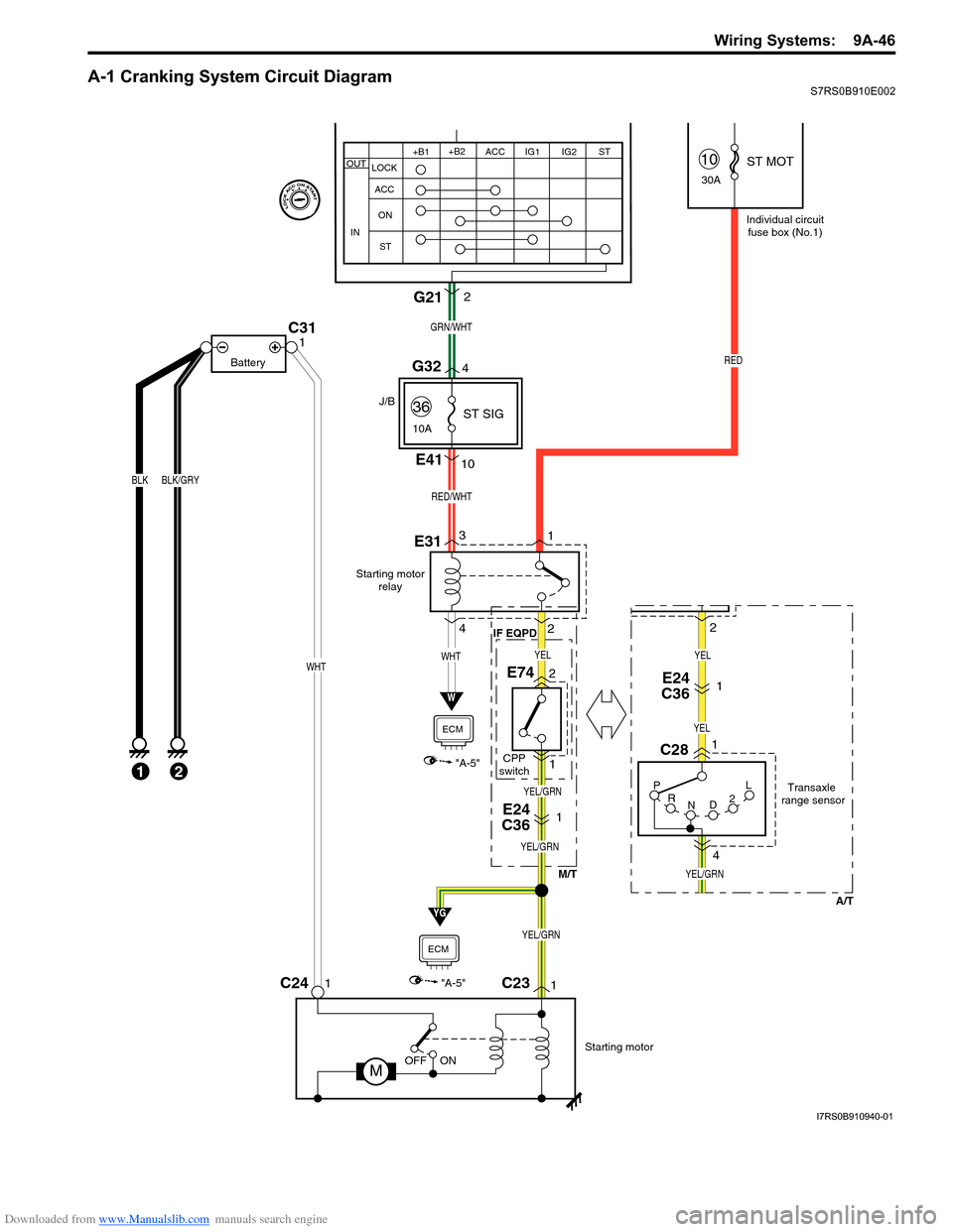
A-1 Cranking System Circuit DiagramS7RS0B910E002
Starting motorrelay
W
"A-5"
ECM
P
R N D2LTransaxle
range sensor
C28
E741
4
E31
C231C241
Starting motor
MOFF ON
BLK
1
BLK/GRY
C311
Battery
E24
C361
RED
Individual circuit
fuse box (No.1)
10
30A
36
10A
WHTWHT
M/T
IF EQPD
E24
C361
J/B
A/T
E4110
13
2
4
RED/WHT
2 ST MOT
ST SIG
YEL/GRN
YG
"A-5"
ECM
GRN/WHT
G212
YEL/GRN
YEL/GRN
YEL
YEL/GRN
YEL
YEL
G324
+B1
LOCK
ACC
ON
ST ACC IG1 IG2
STOUT
IN
+B2
21CPP
switch
2
I7RS0B910940-01