1A-19 SUZUKI SWIFT 2007 2.G Service Workshop Manual
[x] Cancel search | Manufacturer: SUZUKI, Model Year: 2007, Model line: SWIFT, Model: SUZUKI SWIFT 2007 2.GPages: 1496, PDF Size: 34.44 MB
Page 45 of 1496
Downloaded from www.Manualslib.com manuals search engine Table of Contents 1- i
1
Section 1
CONTENTS
Engine
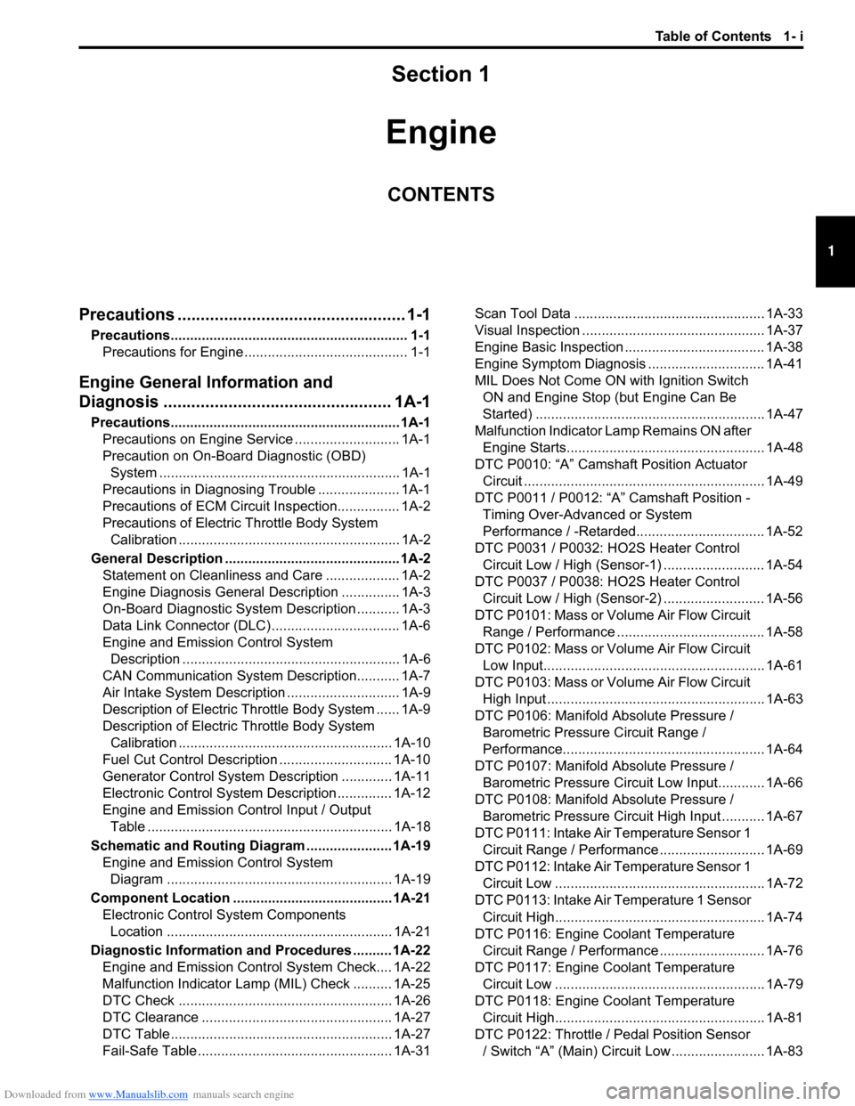
Precautions ................................................. 1-1
Precautions............................................................. 1-1
Precautions for Engine .......................................... 1-1
Engine General Information and
Diagnosis ............. .................................... 1A-1
Precautions........................................................... 1A-1
Precautions on Engine Service ........................... 1A-1
Precaution on On-Board Diagnostic (OBD) System .............................................................. 1A-1
Precautions in Diagnosing Trouble ..................... 1A-1
Precautions of ECM Circuit Inspection................ 1A-2
Precautions of Electric Throttle Body System
Calibration ......................................................... 1A-2
General Description ............................................. 1A-2 Statement on Cleanliness and Care ................... 1A-2
Engine Diagnosis General Description ............... 1A-3
On-Board Diagnostic System Description ........... 1A-3
Data Link Connector (DLC) ................................. 1A-6
Engine and Emission Control System Description ........................................................ 1A-6
CAN Communication System Description........... 1A-7
Air Intake System Description ............................. 1A-9
Description of Electric Throttle Body System ...... 1A-9
Description of Electric Throttle Body System Calibration ....................................................... 1A-10
Fuel Cut Control Description ............................. 1A-10
Generator Control System Description ............. 1A-11
Electronic Control System Description .............. 1A-12
Engine and Emission Control Input / Output Table ............................................................... 1A-18
Schematic and Routing Diagram ...................... 1A-19 Engine and Emission Control System Diagram .......................................................... 1A-19
Component Locatio n ......................................... 1A-21
Electronic Control System Components Location .......................................................... 1A-21
Diagnostic Information and Procedures .......... 1A-22 Engine and Emission Control System Check.... 1A-22
Malfunction Indicator Lamp (MIL) Check .......... 1A-25
DTC Check ....................................................... 1A-26
DTC Clearance ................................................. 1A-27
DTC Table ......................................................... 1A-27
Fail-Safe Table ................ .................................. 1A-31 Scan Tool Data ................................................. 1A-33
Visual Inspection ............................................... 1A-37
Engine Basic Inspection .................................... 1A-38
Engine Symptom Diagnosis .............................. 1A-41
MIL Does Not Come ON with Ignition Switch
ON and Engine Stop (but Engine Can Be
Started) ........................................................... 1A-47
Malfunction Indicator Lamp Remains ON after Engine Starts................................................... 1A-48
DTC P0010: “A” Camshaft Position Actuator Circuit .............................................................. 1A-49
DTC P0011 / P0012: “A” Camshaft Position - Timing Over-Advanced or System
Performance / -Retarded................................. 1A-52
DTC P0031 / P0032: HO2S Heater Control Circuit Low / High (Sensor-1) .......................... 1A-54
DTC P0037 / P0038: HO2S Heater Control Circuit Low / High (Sensor-2) .......................... 1A-56
DTC P0101: Mass or Volume Air Flow Circuit Range / Performance ...................................... 1A-58
DTC P0102: Mass or Volume Air Flow Circuit Low Input......................................................... 1A-61
DTC P0103: Mass or Volume Air Flow Circuit High Input ........................................................ 1A-63
DTC P0106: Manifold Absolute Pressure /
Barometric Pressure Circuit Range /
Performance.................................................... 1A-64
DTC P0107: Manifold Absolute Pressure /
Barometric Pressure Circ uit Low Input............ 1A-66
DTC P0108: Manifold Absolute Pressure /
Barometric Pressure Circ uit High Input ........... 1A-67
DTC P0111: Intake Air Temperature Sensor 1 Circuit Range / Performance ........................... 1A-69
DTC P0112: Intake Air Temperature Sensor 1 Circuit Low ...................................................... 1A-72
DTC P0113: Intake Air Temperature 1 Sensor Circuit High...................................................... 1A-74
DTC P0116: Engine Coolant Temperature Circuit Range / Performance ........................... 1A-76
DTC P0117: Engine Coolant Temperature Circuit Low ...................................................... 1A-79
DTC P0118: Engine Coolant Temperature Circuit High...................................................... 1A-81
DTC P0122: Throttle / Pedal Position Sensor / Switch “A” (Main) Circuit Low ........................ 1A-83
Page 46 of 1496
Downloaded from www.Manualslib.com manuals search engine 1-ii Table of Contents
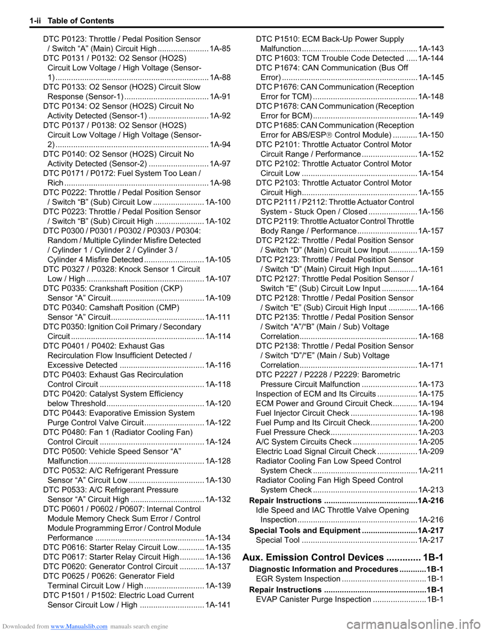
DTC P0123: Throttle / Pedal Position Sensor / Switch “A” (Main) Circuit High ....................... 1A-85
DTC P0131 / P0132: O2 Sensor (HO2S) Circuit Low Voltage / High Voltage (Sensor-
1) ..................................................................... 1A-88
DTC P0133: O2 Sensor (HO2S) Circuit Slow
Response (Sensor- 1) ...................................... 1A-91
DTC P0134: O2 Sensor (HO2S) Circuit No Activity Detected (Sensor -1) ........................... 1A-92
DTC P0137 / P0138: O2 Sensor (HO2S) Circuit Low Voltage / High Voltage (Sensor-
2) ..................................................................... 1A-94
DTC P0140: O2 Sensor (HO2S) Circuit No Activity Detected (Sensor -2) ........................... 1A-97
DTC P0171 / P0172: Fuel System Too Lean / Rich ................................................................. 1A-98
DTC P0222: Throttle / Pedal Position Sensor / Switch “B” (Sub) Circuit Low ....................... 1A-100
DTC P0223: Throttle / Pedal Position Sensor / Switch “B” (Sub) Circuit High ...................... 1A-102
DTC P0300 / P0301 / P0302 / P0303 / P0304: Random / Multiple Cylin der Misfire Detected
/ Cylinder 1 / Cylinder 2 / Cylinder 3 /
Cylinder 4 Misfire Detected ........................... 1A-105
DTC P0327 / P0328: Knoc k Sensor 1 Circuit
Low / High ..................................................... 1A-107
DTC P0335: Crankshaft Position (CKP) Sensor “A” Circuit .......................................... 1A-109
DTC P0340: Camshaft Position (CMP) Sensor “A” Circuit .......................................... 1A-111
DTC P0350: Ignition Coil Primary / Secondary Circuit ............................................................ 1A-114
DTC P0401 / P0402: Exhaust Gas Recirculation Flow Insufficient Detected /
Excessive Detected ...................................... 1A-116
DTC P0403: Exhaust Gas Recirculation Control Circuit ................... ............................ 1A-118
DTC P0420: Catalyst System Efficiency
below Threshold ................ ............................ 1A-120
DTC P0443: Evaporativ e Emission System
Purge Control Valve Circuit ........................... 1A-122
DTC P0480: Fan 1 (Radiator Cooling Fan) Control Circuit ................... ............................ 1A-124
DTC P0500: Vehicle Speed Sensor “A” Malfunction .................................................... 1A-128
DTC P0532: A/C Refrigerant Pressure Sensor “A” Circuit Low ... ............................... 1A-130
DTC P0533: A/C Refrigerant Pressure Sensor “A” Circuit High ................................. 1A-132
DTC P0601 / P0602 / P0607: Internal Control Module Memory Check Sum Error / Control
Module Programming Error / Control Module
Performance ................................................. 1A-134
DTC P0616: Starter Relay Circuit Low............ 1A-135
DTC P0617: Starter Relay Circuit High ........... 1A-136
DTC P0620: Generator Control Circuit ........... 1A-137
DTC P0625 / P0626: Generator Field Terminal Circuit Low / High . .......................... 1A-139
DTC P1501 / P1502: Electric Load Current Sensor Circuit Low / High . ............................ 1A-141 DTC P1510: ECM Back-Up Power Supply
Malfunction .................................................... 1A-143
DTC P1603: TCM Trouble Code Detected ..... 1A-144
DTC P1674: CAN Communication (Bus Off Error) ............................................................. 1A-145
DTC P1676: CAN Communication (Reception Error for TCM) ............................................... 1A-148
DTC P1678: CAN Communication (Reception Error for BCM) ............................................... 1A-149
DTC P1685: CAN Communication (Reception Error for ABS/ESP ® Control Module) ........... 1A-150
DTC P2101: Throttle Actuator Control Motor Circuit Range / Performance ......................... 1A-152
DTC P2102: Throttle Actuator Control Motor Circuit Low .................................................... 1A-154
DTC P2103: Throttle Actuator Control Motor Circuit High.................................................... 1A-155
DTC P2111 / P2112: Throttle Actuator Control System - Stuck Open / Closed ...................... 1A-156
DTC P2119: Throttle Actu ator Control Throttle
Body Range / Performance ........................... 1A-157
DTC P2122: Throttle / Pedal Position Sensor / Switch “D” (Main) Circuit Low Input............. 1A-159
DTC P2123: Throttle / Pedal Position Sensor / Switch “D” (Main) Circuit High Input ............ 1A-161
DTC P2127: Throttle Pedal Position Sensor / Switch “E” (Sub) Circuit Low Input ................ 1A-164
DTC P2128: Throttle / Pedal Position Sensor
/ Switc
h “E” (Sub) Circuit High Input ............. 1A-166
DTC P2135: Throttle / Pedal Position Sensor / Switch “A”/“B” (Main / Sub) Voltage
Correlation..................................................... 1A-168
DTC P2138: Throttle / Pedal Position Sensor / Switch “D”/“E” (Main / Sub) Voltage
Correlation..................................................... 1A-171
DTC P2227 / P2228 / P2229: Barometric Pressure Circuit Malfunction ......................... 1A-173
Inspection of ECM and Its Circuits .................. 1A-175
ECM Power and Ground Circuit Check........... 1A-194
Fuel Injector Circuit Check .............................. 1A-198
Fuel Pump and Its Circuit Check..................... 1A-200
Fuel Pressure Check....................................... 1A-203
A/C System Circuits Check ............................. 1A-205
Electric Load Signal Circuit Check .................. 1A-209
Radiator Cooling Fan Low Speed Control System Check ............................................... 1A-211
Radiator Cooling Fan High Speed Control System Check ............................................... 1A-213
Repair Instructions ......... .................................1A-216
Idle Speed and IAC Throttle Valve Opening Inspection ...................................................... 1A-216
Special Tools and Equipmen t .........................1A-217
Special Tool .................................................... 1A-217
Aux. Emission Control Devices ............. 1B-1
Diagnostic Information and Procedures ............1B-1
EGR System Inspection ...................................... 1B-1
Repair Instructions ............ ..................................1B-1
EVAP Canister Purge Inspec tion ........................ 1B-1
Page 69 of 1496
Downloaded from www.Manualslib.com manuals search engine Engine General Information and Diagnosis: 1A-19
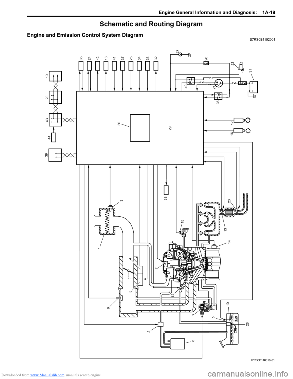
Schematic and Routing Diagram
Engine and Emission Control System DiagramS7RS0B1102001
26 10
9 7
8
14 13
23
11
15
12
2 6
5 1
3
30
29
38
1617 36
31
22
21 40
27
4
28
19
43
39
20
32184233342537413524
44
I7RS0B110010-01
Page 240 of 1496
Downloaded from www.Manualslib.com manuals search engine 1A-190 Engine General Information and Diagnosis:
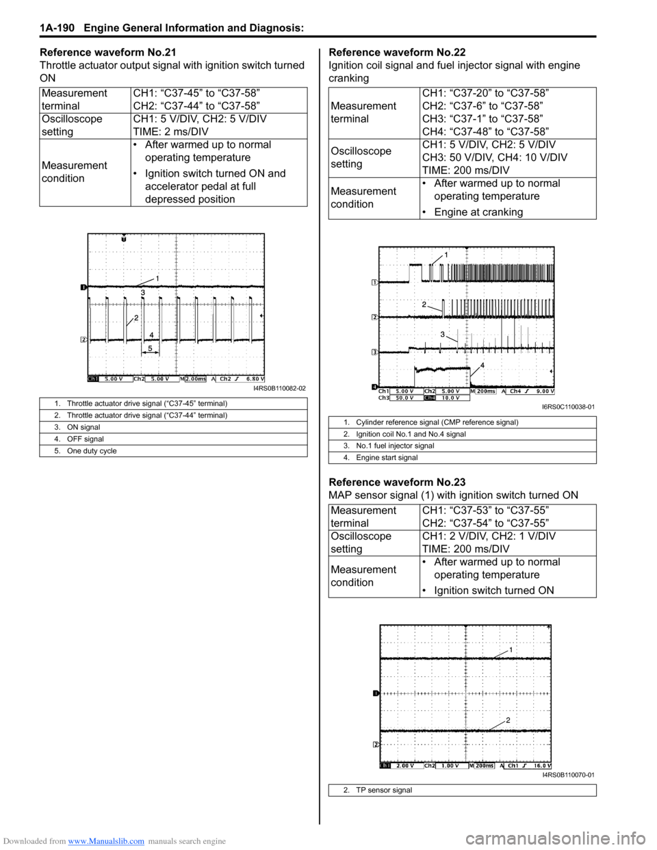
Reference waveform No.21
Throttle actuator output signal with ignition switch turned
ONReference waveform No.22
Ignition coil signal and fuel injector signal with engine
cranking
Reference waveform No.23
MAP sensor signal (1) with ignition switch turned ON
Measurement
terminal
CH1: “C37-45” to “C37-58”
CH2: “C37-44” to “C37-58”
Oscilloscope
setting CH1: 5 V/DIV, CH2: 5 V/DIV
TIME: 2 ms/DIV
Measurement
condition • After warmed up to normal
operating temperature
• Ignition switch turned ON and accelerator pedal at full
depressed position
1. Throttle actuator drive signal (“C37-45” terminal)
2. Throttle actuator drive signal (“C37-44” terminal)
3. ON signal
4. OFF signal
5. One duty cycle
I4RS0B110082-02
Measurement
terminal CH1: “C37-20” to “C37-58”
CH2: “C37-6” to “C37-58”
CH3: “C37-1” to “C37-58”
CH4: “C37-48” to “C37-58”
Oscilloscope
setting CH1: 5 V/DIV, CH2: 5 V/DIV
CH3: 50 V/DIV, CH4: 10 V/DIV
TIME: 200 ms/DIV
Measurement
condition • After warmed up to normal
operating temperature
• Engine at cranking
1. Cylinder reference signal (CMP reference signal)
2. Ignition coil No.1 and No.4 signal
3. No.1 fuel injector signal
4. Engine start signal
Measurement
terminal CH1: “C37-53” to “C37-55”
CH2: “C37-54” to “C37-55”
Oscilloscope
setting CH1: 2 V/DIV, CH2: 1 V/DIV
TIME: 200 ms/DIV
Measurement
condition • After warmed up to normal
operating temperature
• Ignition switch turned ON
2. TP sensor signal
I6RS0C110038-01
I4RS0B110070-01
Page 241 of 1496
Downloaded from www.Manualslib.com manuals search engine Engine General Information and Diagnosis: 1A-191
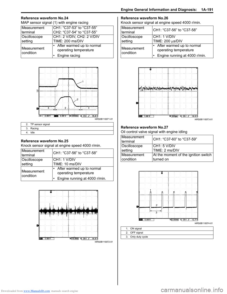
Reference waveform No.24
MAP sensor signal (1) with engine racing
Reference waveform No.25
Knock sensor signal at engine speed 4000 r/min.Reference waveform No.26
Knock sensor signal at engine speed 4000 r/min.
Reference waveform No.27
Oil control valve signal with engine idling
Measurement
terminal
CH1: “C37-53” to “C37-55”
CH2: “C37-54” to “C37-55”
Oscilloscope
setting CH1: 2 V/DIV, CH2: 2 V/DIV
TIME: 200 ms/DIV
Measurement
condition • After warmed up to normal
operating temperature
• Engine racing
2. TP sensor signal
3. Racing
4. Idle
Measurement
terminal CH1: “C37-56” to “C37-58”
Oscilloscope
setting CH1: 1 V/DIV
TIME: 10 ms/DIV
Measurement
condition • After warmed up to normal
operating temperature
• Engine running at 4000 r/min.
I4RS0B110071-01
I4RS0B110072-01
Measurement
terminal CH1: “C37-56” to “C37-58”
Oscilloscope
setting CH1: 1 V/DIV
TIME: 200
µs/DIV
Measurement
condition • After warmed up to normal
operating temperature
• Engine running at 4000 r/min.
Measurement
terminal CH1: “C37-60” to “C37-59”
Oscilloscope
setting CH1: 5 V/DIV
TIME: 2 ms/DIV
Measurement
condition At the moment of the ignition switch
turned on
1. ON signal
2. OFF signal
3. Only duty cycle
I4RS0B110073-01
I4RS0B110074-01
Page 242 of 1496
Downloaded from www.Manualslib.com manuals search engine 1A-192 Engine General Information and Diagnosis:
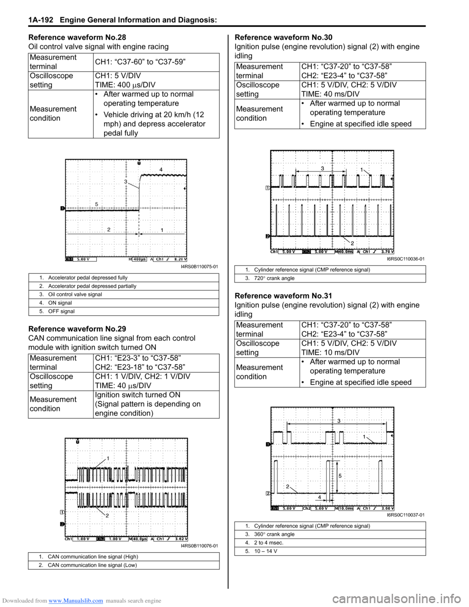
Reference waveform No.28
Oil control valve signal with engine racing
Reference waveform No.29
CAN communication line signal from each control
module with ignition switch turned ONReference waveform No.30
Ignition pulse (engine revolution) signal (2) with engine
idling
Reference waveform No.31
Ignition pulse (engine revolution) signal (2) with engine
idling
Measurement
terminal
CH1: “C37-60” to “C37-59”
Oscilloscope
setting CH1: 5 V/DIV
TIME: 400
µs/DIV
Measurement
condition • After warmed up to normal
operating temperature
• Vehicle driving at 20 km/h (12 mph) and depress accelerator
pedal fully
1. Accelerator pedal depressed fully
2. Accelerator pedal depressed partially
3. Oil control valve signal
4. ON signal
5. OFF signal
Measurement
terminal CH1: “E23-3” to “C37-58”
CH2: “E23-18” to “C37-58”
Oscilloscope
setting CH1: 1 V/DIV, CH2: 1 V/DIV
TIME: 40
µs/DIV
Measurement
condition Ignition switch turned ON
(Signal pattern is depending on
engine condition)
1. CAN communication line signal (High)
2. CAN communication line signal (Low)
I4RS0B110075-01
I4RS0B110076-01
Measurement
terminal
CH1: “C37-20” to “C37-58”
CH2: “E23-4” to “C37-58”
Oscilloscope
setting CH1: 5 V/DIV, CH2: 5 V/DIV
TIME: 40 ms/DIV
Measurement
condition • After warmed up to normal
operating temperature
• Engine at specified idle speed
1. Cylinder reference signal (CMP reference signal)
3. 720 ° crank angle
Measurement
terminal CH1: “C37-20” to “C37-58”
CH2: “E23-4” to “C37-58”
Oscilloscope
setting CH1: 5 V/DIV, CH2: 5 V/DIV
TIME: 10 ms/DIV
Measurement
condition • After warmed up to normal
operating temperature
• Engine at specified idle speed
1. Cylinder reference signal (CMP reference signal)
3. 360 ° crank angle
4. 2 to 4 msec.
5. 10 – 14 V
I6RS0C110036-01
I6RS0C110037-01
Page 243 of 1496
Downloaded from www.Manualslib.com manuals search engine Engine General Information and Diagnosis: 1A-193
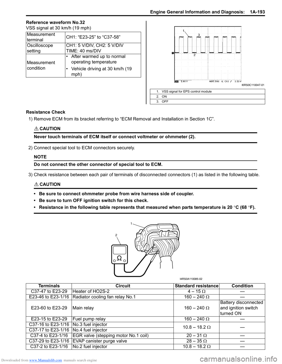
Reference waveform No.32
VSS signal at 30 km/h (19 mph)
Resistance Check1) Remove ECM from its bracket referring to “ECM Removal and Installation in Section 1C”.
CAUTION!
Never touch terminals of ECM itself or connect voltmeter or ohmmeter (2).
2) Connect special tool to ECM connectors securely.
NOTE
Do not connect the other connector of special tool to ECM.
3) Check resistance between each pair of terminals of disconnected connectors (1) as listed in the following table.
CAUTION!
• Be sure to connect ohmmeter probe from wire harness side of coupler.
• Be sure to turn OFF ignition switch for this check.
• Resistance in the following table represents that measured when parts temperature is 20 °C (68 °F).
Measurement
terminal CH1: “E23-25” to “C37-58”
Oscilloscope
setting CH1: 5 V/DIV, CH2: 5 V/DIV
TIME: 40 ms/DIV
Measurement
condition • After warmed up to normal
operating temperature
• Vehicle driving at 30 km/h (19 mph)
1. VSS signal for EPS control module
2. ON
3. OFF
I6RS0C110047-01
1
2
I4RS0A110086-02
Terminals CircuitStandard resistance Condition
C37-47 to E23-29 Heater of HO2S-2 4 – 15 Ω—
E23-46 to E23-1/16 Radiator cooling fan relay No.1 160 – 240 Ω —
E23-60 to E23-29 Main relay 160 – 240 ΩBattery disconnected
and ignition switch
turned ON
E23-15 to E23-29 Fuel pump relay 160 – 240 Ω —
C37-16 to E23-1/16 No.3 fuel injector 10.8 – 18.2 Ω —
C37-17 to E23-1/16 No.4 fuel injector
C37-4 to E23-1/16 EGR valve (st epping motor No.1 coil) 20 – 31 Ω —
C37-29 to E23-1/16 EVAP canister purge valve 28 – 35 Ω —
C37-2 to E23-1/16 No.2 fuel injector 10.8 – 18.2 Ω—
Page 244 of 1496
Downloaded from www.Manualslib.com manuals search engine 1A-194 Engine General Information and Diagnosis:
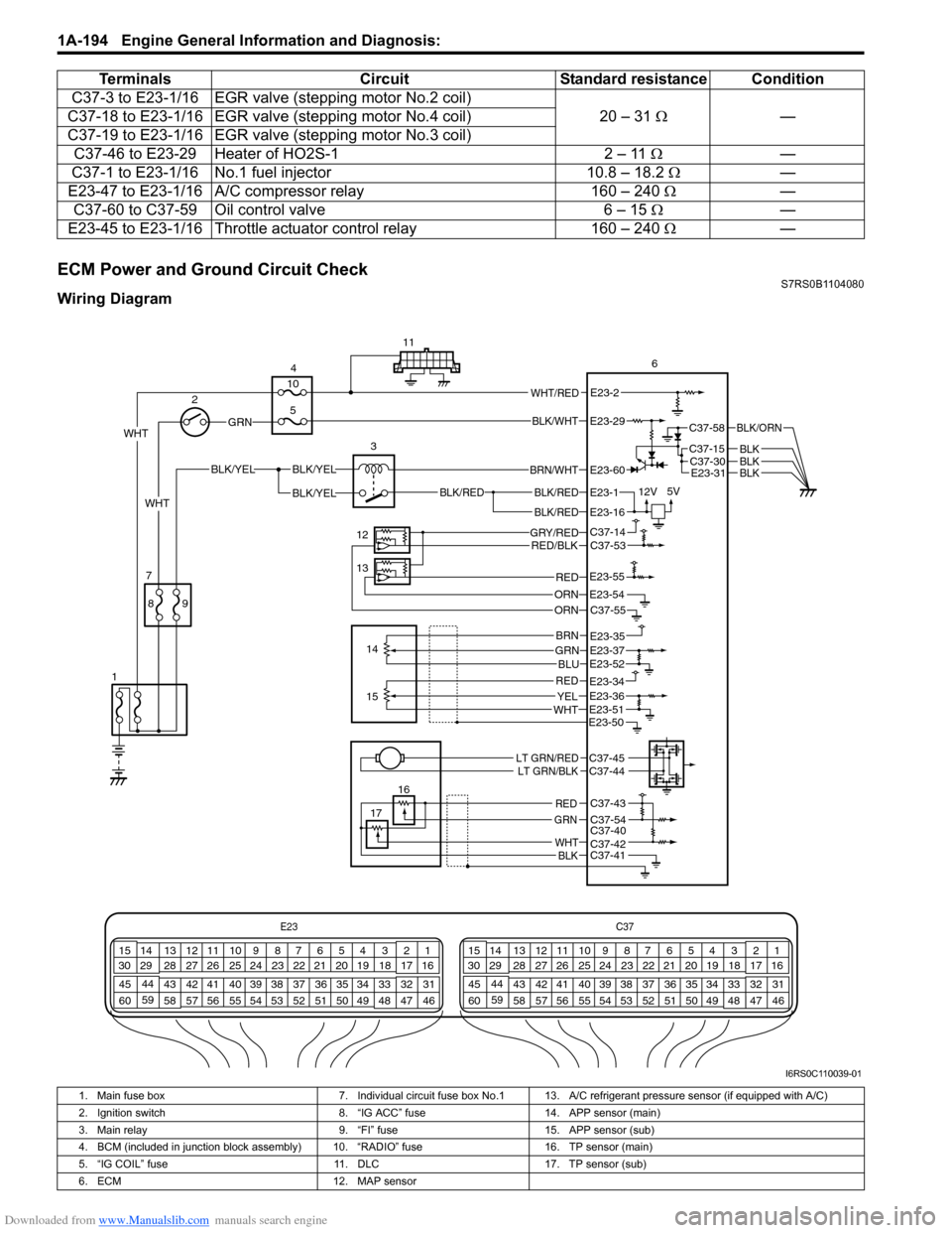
ECM Power and Ground Circuit CheckS7RS0B1104080
Wiring DiagramC37-3 to E23-1/16 EGR valve
(stepping motor No.2 coil)
20 – 31 Ω —
C37-18 to E23-1/16 EGR valv e (stepping motor No.4 coil)
C37-19 to E23-1/16 EGR valv e (stepping motor No.3 coil)
C37-46 to E23-29 Heater of HO2S-1 2 – 11 Ω—
C37-1 to E23-1/16 No.1 fuel injector 10.8 – 18.2 Ω —
E23-47 to E23-1/16 A/C compressor relay 160 – 240 Ω —
C37-60 to C37-59 Oil control valve 6 – 15 Ω —
E23-45 to E23-1/16 Throttle actuator control relay 160 – 240 Ω —
Terminals
CircuitStandard resistance Condition
E23 C37
34
1819
567
1011
17
20
47 46
495051
2122
52 16
25 9
24
14
29
55
57 54 53
59
60 58 2
262728
15
30
56 4832 31
34353637
40
42 39 38
44
45 43 41 331
1213
238
34
1819
567
1011
17
20
47 46
495051
2122
52 16
25 9
24
14
29
55
57 54 53
59
60 58 2
262728
15
30
56 4832 31
34353637
40
42 39 38
44
45 43 41 331
1213
238
BLK/RED
BLK/REDBLK/RED
BLK/YELBLK/YEL
BLK/YEL
GRN
BRN/WHT
12V
5VE23-1
E23-60
E23-16
WHT 2
4
11
6
3
12
13 14
7
1
16
17
89
15
10
5
WHT/REDE23-2
C37-58
C37-15C37-30
BLK/ORN
BLKBLKE23-31BLK
WHT
GRY/REDRED/BLK
ORN
C37-14C37-53
C37-55E23-54
REDE23-55
GRNBRN
BLU
REDYELWHT
E23-35E23-37E23-52
E23-51
E23-34E23-36
E23-50
LT GRN/REDLT GRN/BLKC37-45C37-44
C37-43
C37-54C37-40C37-42C37-41
RED
GRN
WHTBLK
ORN
BLK/WHTE23-29
I6RS0C110039-01
1. Main fuse box 7. Individual circuit fuse box No.1 13. A/C refrigerant pressure sensor (if equipped with A/C)
2. Ignition switch 8. “IG ACC” fuse14. APP sensor (main)
3. Main relay 9. “FI” fuse15. APP sensor (sub)
4. BCM (included in junction block assembly) 10. “RADIO” fuse 16. TP sensor (main)
5. “IG COIL” fuse 11. DLC17. TP sensor (sub)
6. ECM 12. MAP sensor
Page 245 of 1496
Downloaded from www.Manualslib.com manuals search engine Engine General Information and Diagnosis: 1A-195
Circuit Description
When the ignition switch is turned ON, the main relay turns ON (the contact point closes) and the main power is
supplied to ECM.
Troubleshooting
NOTE
When measuring circuit voltage, resistance and/or pulse signal at ECM connector, connect the special
tool to ECM and/or the ECM connectors referri ng to “Inspection of ECM and Its Circuits”.
StepAction YesNo
1 Circuit fuse check
1) Disconnect connectors from ECM with ignition switch
turned OFF.
2) Check for proper connection to ECM connector at “E23- 2”, “E23-29”, “E23-60”, “E23-1”, “E23-16”, “E23-31”,
“C37-58”, “C37-15” and “C37-30” terminals.
3) If OK, check “RADIO” fuse and “IG COIL” fuse for blowing.
Are “RADIO” fuse and “IG COIL” fuse in good condition? Go to Step 2.
Replace fuse (s) and
check for short in
circuits connected to
fuse(s).
2 Power supply circuit check
1) Measure voltage between “E23-2” terminal of ECM
connector and body ground.
Is voltage 10 – 14 V? Go to Step 3.
“WHT/RED” or “WHT”
wire is open circuit.
3 Ignition signal check
1) Turn ignition switch to ON position.
2) Measure voltage between “E23-29” terminal of ECM
connector and body ground.
Is voltage 10 – 14 V? Go to Step 4.
“BLK/WHT” or “GRN”
wire is open circuit.
4 Main relay circuit check
1) Turn ignition switch to OFF position.
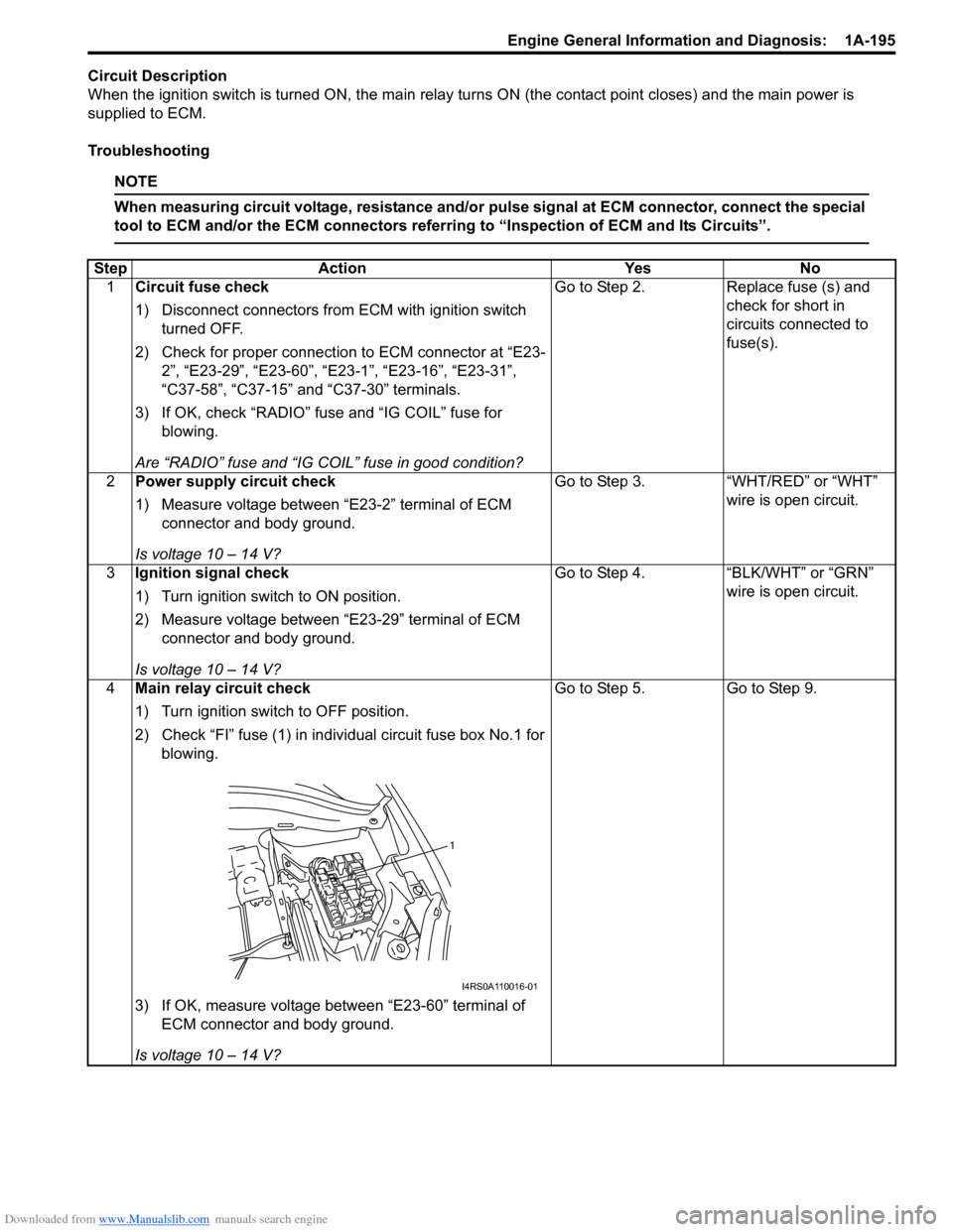
2) Check “FI” fuse (1) in indivi dual circuit fuse box No.1 for
blowing.
3) If OK, measure voltage between “E23-60” terminal of ECM connector and body ground.
Is voltage 10 – 14 V? Go to Step 5.
Go to Step 9.
1
I4RS0A110016-01
Page 246 of 1496
Downloaded from www.Manualslib.com manuals search engine 1A-196 Engine General Information and Diagnosis:
5Main relay circuit check
1) Connect connectors to ECM with ignition switch turned
OFF.
2) Turn ignition switch to ON position.
3) Measure voltage between “E23-60” terminal of ECM connector and body ground.
Is voltage 0 – 1 V? Go to Step 7. Go to Step 6.
6 ECM ground circuit check
1) Turn ignition switch to OFF position.
2) Disconnect connectors from ECM.
3) Measure resistance between each “E23-31”, “C37-58”,
“C37-15” and “C37-30” terminals of ECM connector and
body ground.
Is resistance 1
Ω or less? Substitute a known-
good ECM and recheck.
“BLK/ORN” or “BLK”
wire is open or high
resistance circuit.
7 Main relay circuit check
1) Disconnect connectors from ECM with ignition switch
turned OFF.
2) Using service wire, ground “E23-60” terminal of ECM connector and measure voltage between each “E23-1”
and “E23-16” terminals of ECM connector and body
ground.
Is voltage 10 – 14 V? Go to Step 11. Go to Step 8.
8 Main relay circuit check
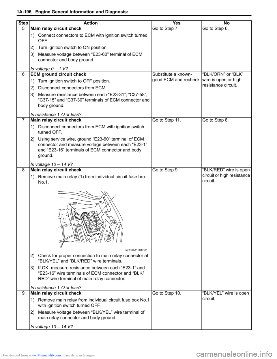
1) Remove main relay (1) from individual circuit fuse box
No.1.
2) Check for proper connection to main relay connector at “BLK/YEL” and “BLK/RED” wire terminals.
3) If OK, measure resistance between each “E23-1” and “E23-16” wire terminals of ECM connector and “BLK/
RED” wire terminal of main relay connector.
Is resistance 1
Ω or less? Go to Step 9. “BLK/RED” wire is open
circuit or high resistance
circuit.
9 Main relay circuit check
1) Remove main relay from individual circuit fuse box No.1
with ignition swit ch turned OFF.
2) Measure voltage between “BLK/YEL” wire terminal of main relay connector and body ground.
Is voltage 10 – 14 V? Go to Step 10. “BLK/YEL” wire is open
circuit.
Step Action Yes No
1
I4RS0A110017-01