Amber warning SUZUKI SWIFT 2007 2.G Service Workshop Manual
[x] Cancel search | Manufacturer: SUZUKI, Model Year: 2007, Model line: SWIFT, Model: SUZUKI SWIFT 2007 2.GPages: 1496, PDF Size: 34.44 MB
Page 87 of 1496

Downloaded from www.Manualslib.com manuals search engine Engine General Information and Diagnosis: 1A-37
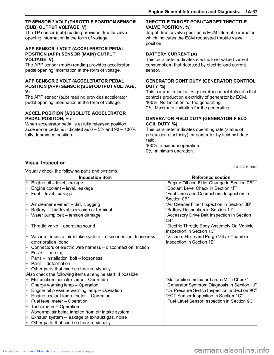
TP SENSOR 2 VOLT (THROTTLE POSITION SENSOR
(SUB) OUTPUT VOLTAGE, V)
The TP sensor (sub) reading provides throttle valve
opening information in the form of voltage.
APP SENSOR 1 VOLT (ACCELERATOR PEDAL
POSITION (APP) SENSOR (MAIN) OUTPUT
VOLTAGE, V)
The APP sensor (main) read ing provides accelerator
pedal opening information in the form of voltage.
APP SENSOR 2 VOLT (ACCELERATOR PEDAL
POSITION (APP) SENSOR (S UB) OUTPUT VOLTAGE,
V)
The APP sensor (sub) reading provides accelerator
pedal opening information in the form of voltage.
ACCEL POSITION (ABSOLUTE ACCELERATOR
PEDAL POSITION, %)
When accelerator pedal is at fully released position,
accelerator pedal is indicated as 0 – 5% and 90 – 100%
fully depressed position. THROTTLE TARGET POSI (TARGET THROTTLE
VALVE POSITION, %)
Target throttle valve position is ECM internal parameter
which indicates the ECM requested throttle valve
position.
BATTERY CURRENT (A)
This parameter indicates elec
tric load value (current
consumption) that detected by electric load current
sensor.
GENERATOR CONT DUTY (GENERATOR CONTROL
DUTY, %)
This parameter indicates generator control duty ratio that
controls production electricity of generator by ECM.
100%: No limitation for the generating
0%: Maximum limitation for the generating
GENERATOR FIELD DUTY (GENERATOR FIELD
COIL DUTY, %)
This parameter indicates ope rating rate (status of
production electricity) for gen erator by field coil duty
ratio.
100%: maximum operation.
0%: minimum operation.
Visual InspectionS7RS0B1104008
Visually check the following parts and systems.
Inspection item Reference section
• Engine oil – level, leakage “Engine Oil and Filter Change in Section 0B”
• Engine coolant – level, leakage “Co olant Level Check in Section 1F”
• Fuel – level, leakage “Fuel Lines and Connections Inspection in Section 0B”
• Air cleaner element – dirt, clogging “Air Cleaner Filter Inspection in Section 0B”
• Battery – fluid level, corrosion of terminal “Battery Description in Section 1J”
• Water pump belt – tension damage “Accessory Drive Belt Inspection in Section 0B”
• Throttle valve – operating sound “Electric Throttle Body Assembly On-Vehicle Inspection in Section 1C”
• Vacuum hoses of air intake system – disconnection, looseness,
deterioration, bend “Vacuum Hose and Purge Valve Chamber
Inspection in Section 1B”
• Connectors of electric wire harness – disconnection, friction
• Fuses – burning
• Parts – installation, bolt – looseness
• Parts – deformation
• Other parts that can be checked visually
Also check the following items at engine start, if possible
• Malfunction indicator lamp – Operation “Malfunction Indicator Lamp (MIL) Check”
• Charge warning lamp – Operation “Genera tor Symptom Diagnosis in Section 1J”
• Engine oil pressure warning lamp – Operation “O il Pressure Switch Inspection in Section 9C”
• Engine coolant temp. meter – Operation “ECT Sensor Inspection in Section 1C”
• Fuel level meter – Operation “Fuel Level Sensor Inspection in Section 9C”
• Tachometer – Operation
• Abnormal air being inhaled from air intake system
• Exhaust system – leakage of exhaust gas, noise
• Other parts that can be checked visually
Page 270 of 1496

Downloaded from www.Manualslib.com manuals search engine 1B-3 Aux. Emission Control Devices:
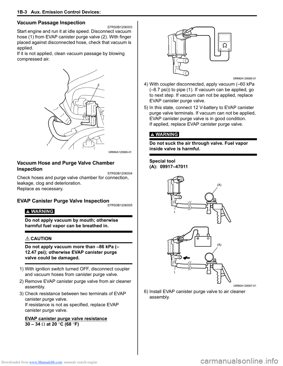
Vacuum Passage InspectionS7RS0B1206003
Start engine and run it at idle speed. Disconnect vacuum
hose (1) from EVAP canister purge valve (2). With finger
placed against disconnected hose, check that vacuum is
applied.
If it is not applied, clean vacuum passage by blowing
compressed air.
Vacuum Hose and Purge Valve Chamber
Inspection
S7RS0B1206004
Check hoses and purge valv e chamber for connection,
leakage, clog and deterioration.
Replace as necessary.
EVAP Canister Purge Valve InspectionS7RS0B1206005
WARNING!
Do not apply vacuum by mouth; otherwise
harmful fuel vapor can be breathed in.
CAUTION!
Do not apply vacuum more than –86 kPa (–
12.47 psi); otherwise EVAP canister purge
valve could be damaged.
1) With ignition switch turned OFF, disconnect coupler and vacuum hoses from canister purge valve.
2) Remove EVAP canister purge valve from air cleaner assembly.
3) Check resistance between two terminals of EVAP canister purge valve.
If resistance is not as specified, replace EVAP
canister purge valve.
EVAP canister purge valve resistance
30 – 34 Ω at 20 °C (68 °F) 4) With coupler disconnected, apply vacuum (–60 kPa
(–8.7 psi)) to pipe (1). If vacuum can be applied, go
to next step. If vacuum can not be applied, replace
EVAP canister purge valve.
5) In this state, connect 12 V-battery to EVAP canister purge valve terminals. If vacuum can not be applied,
EVAP canister purge valve is in good condition.
If applied, replace EVAP canister purge valve.
WARNING!
Do not suck the air through valve. Fuel vapor
inside valve is harmful.
Special tool
(A): 09917–47011
6) Install EVAP canister purge valve to air cleaner assembly.
I3RM0A120006-01
I3RM0A120008-01
1
1 (A)
(A)
I3RB0A120007-01